Note : Les descriptions sont présentées dans la langue officielle dans laquelle elles ont été soumises.
CA 02224772 1997-12-16
WO 97!00752 PCT/CA96/00307
GAS KNIFE COOLTNG SYSTEM
The present invention relates to reflow soldering
and more specifically to cooling soldered articles
immediately after soldering.
Printed circuit board assemblies are cooled after
reflow soldering to reduce the temperature of the
soldered articles below the melting temperature of the
solder. In reflow soldering the articles to be soldered
are first covered with a solder paste containing flux
which is then heated in at least one heat zone so that
the solder melts and the flux liquifies permitting the
solder to flow and cover the joint or area to be
soldered. After heating, the soldered articles pass into
a cooling section where the solder is cooled below the
melting temperature, thus hardening the solder on the
circuit board assemblies. In most cases there is also
some liquid or solid flux deposits on the solder which
forms in the cooler section.
One example of a reflow soldering apparatus is
disclosed in U.S. Patent 5,125,556 to Deambrosio and one
example of a cooling unit for a reflow soldering system
is disclosed in U.S. Patent 4,912,857 to Parent et al.
The cooling unit is generally a separate section and
incorporates moving ambient gas via fans or blowers
through a heat exchanger. The recirculation of the
ambient gas can cause problems with regard to flux
deposits in the heat exchangers and within the flow
actuators. These deposits can cause clogging of the heat-
exchangers and flow actuators which can degrade the
cooling performance over time. This results in increased
maintenance and down time.
Various methods of reducing flux deposits in the
cooling section have been attempted. One remedy is a
CA 02224772 1997-12-16
WO 97/00752 PCT/CA96/00307
- 2 -
filtration system wherein gases in the reflow heating
zones are passed through a filtering medium before
entering the cooling zone. This technique is not always
effective as it is difficult to filter out the flux
components when in the vapour phase. Thus, filter
systems may slow the accumulation of flux deposits in the ~
cooling zone, but they do not solve the problem.
Another suggested scheme is a cleaning cycle for the
entire reflow apparatus. In this system, the heating
zones and the cooling zones are heated to a temperature
which allows flux deposits within the oven to vaporize.
Such a procedure, however, has a number of problems, one
of them being due to the large thermal mass of the
heating zones requiring high heating energy which is both
costly and time consuming. There is a three step process
which heats up, bakes out and cools down the complete
apparatus. This requires the shut down of the reflow
apparatus. Another problem is that the recirculating
coolant must be entirely purged from the heat exchanger
used in the cooling zone, otherwise it may rupture as a
result of high pressure at elevated cleaning
temperatures. This last point is of concern because a
failure of the purge system could result in personal
injury.
In most cooling sections of a reflow soldering
apparatus, a high circulation of ambient gas passes
through a heat exchanger to cool the gas. The soldered
articles are then conveyed through the cooled gas. The
two most common gases used in this cooling system are air
and nitrogen. Nitrogen provides an inert process
environment and much brighter solder joints are obtained
in a nitrogen atmosphere as oxidation does not occur on
the surface of the solder.
CA 02224772 2001-06-12
-3-
The present invention relates to a cooling system
for reflow soldering which reduces flux deposits on heat
exchangers and flow actuators in the cooling section.
The system supplies at least one gas stream directed
specifically at the soldered article conveyed through the
cooling section, thus a reduced gas flow is used for
cooling to harden the solder because it is directed
specifically at the soldered articles. The gas stream is
produced in a gas knife and a cleaning cycle is provided
as required to heat the gas knife to a temperature above
flux vaporization, thus removing flux deposits on the gas
knife.
The expression "gas knife" used herein refers to any
device that provides a suitable gas stream, or an
impinging flow cooling system to cool an object. Gas
knife should be considered as a gas flow actuator such as
slot nozzles, round nozzles or arrays of nozzles
positioned to provide an impinging gas flow.
In accordance with one aspect of the invention there
is provided a cooling system for a reflow soldering
apparatus having a heating section followed by a cooling
section, with a conveyor for carrying products to be
soldered through the apparatus. The cooling section
includes a heat exchanger structured to stabilize process
temperature within the cooling section. The cooling
system comprises at least one gas knife in the cooling
section positioned in selected proximity to the heat
exchanger. The gas knife includes a slot nozzle
positioned to direct an impinging gas flow at soldered
products on the conveyor to cool the products, the gas
knife having a separate gas flow source structured such
that the gas flow does not circulate through the heat
exchanger. The cooling system also includes a heater
associated with the gas knife for heating the gas knife
CA 02224772 2001-06-12
-4-
to a temperature above flux vaporization temperature of
flux deposits from the soldered products.
The at least one gas knife may be positioned above
the conveyor directing gas onto the top of the soldered
products and at least one gas knife may be positioned
below the conveyor directing gas onto the underside of
the soldered products. The heater may be attached to the
gas knife.
The cooling system may include a temperature sensor
on the gas knife and a control system to control the
temperature of the gas knife at a predetermined level.
Separate flow control valves may also be included for
normal process flow and for a cleaning cycle. The
separate gas flow source may be structured to provide
non-recirculated gas to the gas knife.
In accordance with another aspect of the invention
there is provided a method of cooling soldered products
passing on a conveyor from a heating section of a reflow
soldering apparatus to a cooling section. The method
includes the steps of directing at least one gas stream
onto the soldered products in the cooling section to cool
the products, and providing cleaning cycles from time to
time wherein the gas is heated above flux vaporization
temperature of flux deposits from the soldered products.
The gas stream may be projected from a gas knife
onto soldered products passing on the conveyor and the
gas knife may be heated above flux vaporization
temperature of flux deposits from the soldered products.
The method may also involve at least two gas
streams, one from a gas knife positioned above the
conveyor to direct gas onto the top of the soldered
CA 02224772 2002-04-04
-4a-
products,~and,one from the gas knife positioned below the
conveyor to direct gas onto the underside of the soldered
products.
The heaters may be provided on the gas knives to
heat the gas knives above flux vaporization temperature.
A temperature sensor and temperature controller may be
provided to control the temperature of the gas knives at
a predetermined level.
The gas stream for normal process flow may be at a
higher flow rate than for the cleaning cycles, and the
gas may include nitrogen and/or air. The method may also
involve a heat exchanger to stabilize process temperature
within the cooling section.
The method may also involve providing the gas stream
in the range from 2.83 m3/hr to 70.8 m3/hr at an input
pressure of 207 kPa - 827 kPa. The separate gas flow
source may be selected from the group consisting of an
air compressor, compressed bottled gas, and a nitrogen
tank.
In accordance with another aspect of the invention
there is provided a cooling system for a reflow soldering
apparatus having a heating section followed by a cooling
section, the cooling section having a heat exchanger
structured to stabilize process temperature therewithin
and the apparatus having a conveyor for carrying products
to be soldered through the apparatus. The cooling system
includes at least one gas knife and a heater in the
cooling section. The gas knife includes a slot nozzle
and is positioned to direct an impinging gas flow at
soldered products on the conveyor to cool the products
and a separate gas flow source structured such that the
gas flow does not circulate through the heat exchanger.
The heater is associated with the gas knife for heating
CA 02224772 2002-04-04
-4b-
the gas knife, to a temperature above a flux vaporization
temperature of flux deposits from the soldered products.
The heat exchanger may be positioned in selected
proximity to the gas knife to stabilize process
temperature within the cooling section, and the heat
exchanger may include a separate cooling system. The
separate cooling system may have a circulated coolant
that passes through an entry into the heat exchanger and
out through an exit.
In drawings which illustrate embodiment's of the
present invention,
Figure 1 is a side elevational schematic view
showing one embodiment of a cooling section of a reflow
soldering apparatus according to the present invention,
Figure 2 is an isometric view showing a gas knife
according to one embodiment of the present invention,
Figure 3 is a block diagram showing a control system
for operating the gas knife cooling system according to
one embodiment of the present invention.
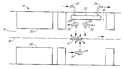
A reflow soldering apparatus 10 according to one
embodiment is shown in Figure 1 wherein a printed circuit
board assembly 12 or other article to be soldered is
conveyed on a conveyor 14 through a heating section 16 to
a cooling section 18. Infrared heaters 20 are shown in
the heating section 16, however, these heaters are but
one type of heater used in reflow soldering apparatus.
Heated gas forced convection systems may be used, or any
other suitable heating system that heats the articles 12
passing on the conveyor 14 through the heating section
15.
CA 02224772 2002-04-04
-4C-
In the cooling section 18 a heat exchanger 22 is
mounted above a plurality of upper gas knives 24 which
direct gas streams onto the top of the soldered articles
12 passing on the conveyor 14. A lower gas knife 25 is
shown positioned below the conveyor 14 so that a gas
CA 02224772 1997-12-16
WO 97/00752 PCT/CA96/00307
- 5 -
stream is directed onto the underside of the soldered
articles 12. The heat exchanger 22 cools and stabilizes
the ambient temperature of the gas in the cooling section
18. This stabilization is desirable when there is heavy
product loading through the cooling section 18. Each of
the soldered articles 12 is cooled giving up heat which
is dissipated in the cooling section 18. A separate
cooling system provides a circulated coolant which may be
air or other gas, water or water/glycol mixture, or other
coolant mixtures, to pass through entry 26 into the heat
exchanger 22 and out through exit 28. In other types of
reflow soldering devices the heat exchanger may utilize
convective cooling with heat dissipation fins or
electronic cooling or other suitable cooling means. A
heat exchanger 22 may be located under the lower gas
knife- 25, beneath the conveyor 14, or outside the cooling
section altogether. The heat exchanger cooling system is
quite separate to the gas streams from the gas knives
24,25. In certain applications a heat exchanger 22 is
not required.
Because the gas knives 24,25 are producing a
directed gas stream rather than the more typical gas
circulation systems utilizing blowers, the problem of
condensation or clogging of the heat exchanger 22 with
flux deposits does not occur because the process gases do
not circulate therethrough.
The gas flow to the gas knives 24,25 is from a
separate source and is generally not recirculated. The
source of compressed gas may be an air compressor,
compressed bottle gas, a nitrogen tank or other suitable
source. The gas is delivered approximately at room
temperature or slightly below, therefore is not cooled
before,passing through the gas entry line 30 to the gas
knives 24,25.
CA 02224772 1997-12-16
WO 97/00752 PCT/CA96/00307
As shown in Figure 2, the gas knife 24 has an
electric heater 32 positioned at the back thereof to heat
the gas knife 24. There is also some heating of the gas
passing through the gas knife 24. The temperature of the
gas knives 24,25 for a cleaning cycle must be above the
vaporizing temperature of the flux, thus the flux
deposits vaporize and this prevents a build up of flux
deposits on the gas knives 24,25. The cleaning cycle
occurs for a sufficient time to vaporize the flux
residues, thus the maintenance of the cooling section is
far simpler than in the existing types of cooling
sections for reflow solder devices where an extensive
heat cycle is necessary to remove flux deposits.
The vaporized flux deposits generally exit from
exhausts at each end of the soldering apparatus 10.
Because the gas supplied to the gas knives 24,25 is from
a separate source, there is a continuous flow of gas out
of the cooling section 18. This continuous gas.flow
evacuates the flux vapour in part which allows it to be
removed from the system by the exhausts at the end of the
soldering apparatus 10. Some flux vapour may condense on
the walls of the soldering apparatus and some may also
re-condense on the gas knives 24,25. However, because
the surface area of the gas knives is small compared to
the overall surface area of the apparatus, there is only
a slight build up of flux deposits.
The number and location of gas knives 24,25 are
determined by the amount of heat transfer desired. The
gas knives are fed gas through a flow controller as shown
in Figure 3. At least one gas knife has a thermocouple
33 referred to as the temperature sensor in Figure 3.
The thermocouple 33 provides a closed loop control of the
heater.
CA 02224772 1997-12-16
WO 97100752 PCT/CA96/00307
_ 7 _
Whereas two upper gas knives 24 are shown arid one
lower gas knife 25, in some types of reflow soldering
devices only a single gas knife, preferably directing a
gas stream on the top surface of the soldered product, is
required.
The purpose of the heat exchanger is to maintain the
required temperature in the cooling section. In
operation cool gas from an exterior source is directed
from the gas knives 24,25 at the soldered articles 12.
The flow of gas through the gas knives is reduced
compared to a normal conventional cooling section.
Figure 3 illustrates a controller arrangement for
controlling the gas flow for normal process cooling and
for a cleaning cycle. For normal process cooling the gas
supply passes through a first valve 34 which is open, a
reducing valve 36, and then enters the gas knives 24,25
through line 30. The second valve 38, which provides a
second gas supply, is closed during normal cooling. In
the cleaning cycle the first valve 34 is closed and the
second valve 38 is open, the compressed gas supply passes
through a second reducing valve 40 which permits a
reduced gas flow for the cleaning cycle as compared to
the normal process cooling flow. When the cleaning cycle
is commenced, the controller 42 also activates the
heaters 32 in the gas knives 24,25, the .temperature of
the heater 32 is controlled by the thermocouple 33. The
heater 32 heats the gas knives 24,25 above the
vaporization temperature of the flux so the flux deposits
on the gas knives vaporize.
The gas flow per knife is preferably in the range
from 100 to 2500 CFH (2.83 m3/hr to 70.8 m3/hr) at an
input pressure of 30 to 120 psi (207 kPa - 827 kPa).
Nitrogen is the preferred gas although other types of
suitable gases may be used. In some instances air may be
CA 02224772 1997-12-16
WO 97/00752
PCT/CA96/00307
_ g _
circulated in the cooling section. The process flow rate
is adjusted based on the amount of heat exchange
required, that is to say, the cooling rate is controlled
by the gas flow and gas temperature. The cleaning cycle
is engaged at intervals appropriate to prevent a build up
of flux residue on the gas knives. When the cycle is
engaged, the gas flow switches to the low flow condition
and the heaters on the knives are energized. Thus, the
knife temperature increases and is held at a preset level
above the vaporization temperature of flux residues. The
cleaning cycle runs for sufficient time for the flux
residues to be removed, the electronic controller then
switches off the heaters and changes the flow to the
process high flow condition for cooling.
The thermal performance of the compressed gas knives
is shown through experiment to be equivalent or superior
to that of existing cooling modules. A low complexity
printed circuit board which measures 5" x 7" (12.7 x 17.8
cm) gave an average liquidus time of 44.25 seconds and a
~t of 3°C with a standard cooling module. Using the gas
knife module of the present invention, the liquidus time
was reduced to an average of 37.0 seconds with a ~t of
5°C. An extremely complex board also showed good
results. The standard cooling module gave an average
liquidus time of 83.2 seconds and a ~t of 47°C while the
gas knife module of the present invention showed an
average liquidus time of 80.8 seconds and a ~t of 32°C.
Experiments were performed to test the effect of the
high velocity gas stream from the gas knife impinging on
solder joints. Tests were run using a two knife module '
operating at input pressures of 44and 80 psi (303 and
552 kPa) and flow rates of 250 and 600 CFH (7 and 17 '
m3/hr). Boards were also soldered without using a gas
knife for reference. The responses evaluated were number
solder bridges and number of components moved.
CA 02224772 1997-12-16
WO 97/00752 PCT/CA96/00307
- 9 -
Statistical analysis of the data did not show any
correlation between component movement and the gas
knives.
In the gas knife module, the gas streams do not
' S circulate through the heat exchanger, thus flux deposits
do not generally occur in the heat exchanger. The gas
knives 24,25 generally provide the coolest surface in the
cooling section, and consequently flux deposits form
thereon.
Various changes may be made to the embodiments shown
herewith without departing from the scope of the present
invention which is limited only by the following claims.