Note : Les descriptions sont présentées dans la langue officielle dans laquelle elles ont été soumises.
CA 02226155 1997-12-30
Attorney Docket No. 8106
ANTI-VIBRATION SYSTEM FOR HIGH SPEED WINDING
OF SHEET MATERIAL AND METHOD THEREFOR
BACKGROUND OF THE INVENTION
The invention relates generally to systems and methods for winding sheet
material about a mandrel, and more particularly for reducing vibration of
rotatable
mandrels having a relatively small diameter, wherein the mandrels are useable
for high
speed winding of stretch film materials about a film core supported thereby.
The winding of sheet material about a core supported by a rotatable
mandrel is known generally and useful in many industries. In one known
application,
for example, stretch film used for wrapping or packaging purposes is wound
about a
cardboard core supportably fitted over a rotatable mandrel to form stretch
film rolls
in a winding operation. Several film cores are typically disposed adjacently
about a
steel mandrel having an expandable air bladder that outwardly extends
engagement
1~ members through openings in the mandrel to retain the film cores
thereabout.
Mandrels of this type are available from Battenfeld Glouchester, Glouchester,
Massachusetts. The mandrel is driven rotatably either directly or indirectly
to wind a
sheet of stretch film often supplied at a constant rate thereabout as
discussed further
below. The stretch film sheet is separated into several adjacent strips, by
slitting
during the winding operation, wherein each strip corresponds to one of the
film cores
thereby forming separate stretch film rolls. In one stretch film winding
system used
for this purpose, two mandrels are mounted on substantially opposing sides of
a
rotatable turret that alternately positions the mandrels relative to the
stretch film
supply, whereby stretch film strips are wound about film cores on one mandrel
while
the other mandrel is prepared for a subsequent winding operation.
In one mode of winding sheet material, referred to as surface winding,
a rotatably driven lay-on roll is disposed axially parallel with the axis of
the mandrel
and in contact initially with a film core disposed about the mandrel and later
with the
sheet material wound thereabout for rotatably driving the mandrel to wind the
sheet
1
CA 02226155 2001-03-13
material about the film core. According to this operation, the sheet material,
which is usually
supplied at a constant rate, is supplied over the lay-on roll, downwardly
between the lay-on
roll and the mandrel and under the mandrel whereupon it is wound about the
film core. The
lay-on roll is thus in direct contact with the surface of the film roll and is
movable, pivotally
or otherwise, away from the mandrel as sheet material wound about the mandrel
increases in
diameter. The rotation rate of the' lay-on roll and the mandrel necessarily
decreases as the
film roll diameter increases in applications where the sheet material is
supplied at a constant
rate. In some surface winding operations, the mandrel is also driven by
auxiliary drive means
that operate, not as a primary mover, but merely to reduce drag caused by the
mandrel
thereby lessening the load on tlae lay-on roll. In another mode of winding
sheet material,
referred to as core winding, the mandrel is rotatably driven directly to wind
sheet material
about the film core.
The mandrels used presently for winding stretch film about film cores are
approximately three inches in diameter and over one-hundred inches in length
and moreover
the mandrels rotate at sufficiently high speeds to wind stretch film supplied
at constant speeds
that may exceed 700 feet per minute. It is desirable in stretch film winding
operations, as
well as other applications, to reduce the diameter of the mandrels to
accommodate smaller
size film cores, which have reduced weight, reduced cost and result in smaller
size film rolls.
But reducing the diameter of such a relatively long mandrel has a tendency to
cause
uncontrollable vibration of the rr~andrel during winding operations,
particularly at higher
winding speeds. The vibration tends to be most severe at resonant frequencies
of the
mandrels and depends on some relation between the length, diameter and
rotation rate thereof.
The practical effect of reducing th.e diameter of relatively long mandrels
used for winding,
2
CA 02226155 2001-03-13
sheet materials is that the winding rate must be reduced to prevent vibration,
which may be
destructive to equipment and injurious to personnel. But since reduced winding
rates
adversely affects productivity, it has heretofore been impractical to realize
the benefits of
reduced film core size by reducin~; mandrel diameter.
In view of the discussion above among other considerations, there exists a
demonstrated need for an advancement in the art of winding sheet material
about a mandrel.
Accordingly the invention seeks to provide novel systems and methods for
winding sheet material about a mandrel that overcomes problems with the prior
art.
Further the invention seeks to provide novel systems and methods for
controlling vibration of an axially rotatable mandrel useable for winding
sheet material
including stretch film thereabout and more particularly for stabilizing long
and relatively
narrow diameter mandrels rotatable at high speeds.
Still Further the invention seeks to provide novel systems and methods for
stabilizing a rotatable mandrel by supportably capturing, or caging, the
mandrel and any sheet
material wound thereabout between first, second and third roller members to
prevent or at
least substantially reduce vibration of the rotatable mandrel, wherein the
roller members are
retractable away from the mandrel to accommodate sheet material wound
increasingly
thereabout to form a roll.
Further still the invention seeks to provide novel systems and methods for
stabilizing a rotatable mandrel by supportably capturing the mandrel between
first, second and
third roller members, wherein at least the first and second roller members are
biasable toward
the mandrel with pneumatic pressure from corresponding air over oil cylinders
and the first
3
CA 02226155 2001-03-13
and second roller members are movable away from the mandrel against hydraulic
resistance
from the corresponding air over oil cylinders to accommodate sheet material
wound
increasingly about the mandrel.
Yet further the invention seeks to provide novel systems and methods for
rotatably coupling first and second mandrels to a rotatable turret that
alternately positions the
mandrels relative to a power driven lay-on roll, which rotatably surface
drives the mandrel
and sheet material wound thereabout, wherein each mandrel has at least one
corresponding
set of first and second roller members disposed about an axial segment of the
mandrel to
cooperate with the lay-on roll for supportably capturing the mandrel
therebetween and
preventing or at least reducing substantially vibration of the rotating
mandrel.
These and other aspects, features and advantages of the present invention will
become more fully apparent upon consideration of the following Detailed
Description of the
Invention with the accompanying; Drawings, which may be disproportionate for
ease of
understanding, wherein like structure and steps are referenced by
corresponding numerals and
indicators.
BRIEF DESCRIPTION OF THE DRAWINGS
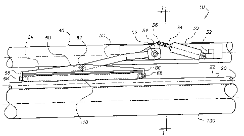
FIG. 1 is a partial top plan view of a system for reducing vibration of an
axially
rotatable mandrel useable for winding sheet material thereabout according to
an exemplary
embodiment of the invention.
FIG. 2 is a sectional view of a system for reducing vibration of a rotatable
mandrel including first and second mandrels rotatably coupled to a rotatable
turret, which is
representative in part of a sectional view along lines I - I of FIG. 1.
FIG. 3 is a schematic diagram of a fluidic circuit useable in connection with
the system of FIGS. I and 2 according to an exemplary embodiment of the
invention.
4
t CA 02226155 1997-12-30
Philip G. SCHERER et al. Attorney Docket No. 8106
"Anti-Vibration System for High Speed
Winding of Sheet Material and Method Therefor"
DETAILED DESCRIPTION OF THE INVENTION
t..-
FIGS. 1 and 2 show partial and sectional views of a system 10 for
controlling vibration of an axially rotatable mandrel 20 useable generally for
winding
sheet material, not shown in the drawing, about the mandrel, and more
particularly for
winding stretch film about one or more cardboard cores 22 disposed and
retained
.about the mandrel 20 as discussed above. In some applications, however, it
may be
advantageous to wind the sheet material about the mandrel 20 directly without
a core
22 therebetween.
FIG. 2 shows the system 10 including generally first, second and third
roller members 110, 120 and 130 rotatably contactable with at least one of the
mandrel
and sheet material wound thereabout. Any reference to the first, second and
third
roller members being in contact with the sheet material includes contact with
the core
22, which may occur initially during winding operations. The first. second and
third
15 roller members 110, 120 and 130 are arranged about the mandrel axis 21 so
that the
mandrel 20 and any sheet material wound thereabout is supportably captured
therebetween to prevent or at least substantially reduce vibration of the
rotatable
mandrel 20. The roller members 110, 120 and 130 are thus disposed along
different
radials of the mandrel axis 21, wherein each radial is separated by some
amount of
20 angular measure sufficiently large to capture, or cage, and retain the
mandrel
therebetween.
In the exemplary embodiment, the first, second and third roller members
110, 120 and 130 are disposed about a common lengthwise axial segment of the
mandrel 20 as shown best in FIG. 1. According to this aspect of the invention,
the
second roller member 120, not visible in FIG. 1, is disposed along the same
lengthwise
axial segment of the mandrel 20 as the first roller member 110, but along
another
radial extending from the mandrel axis 21 as shown in FIG. 2. In other
embodiments,
however, one or more of the first, second and third roller members 110, 120,
and 130
CA 02226155 1997-12-30
Philip G. SCHERER et al. Attorney Docket No. 8106
"Anti-Vibration System for High Speed
Winding of Sheet Material and Method Therefor"
may be offset relative to one another lengthwise along the axial dimension of
the
mandrel 20 to provide more or less overlap therebetween.
Additional sets of first, second and third roller members 110, 120 and
130 may also be arranged similarly about other lengthwise axial portions of
the
S mandrel 20 so that the mandrel and any sheet material wound thereabout is
supportably captured between the first, second and third roller members 110,
120 and
130 to prevent or at least substantially reduce vibration along the full
length of the
rotatable mandrel 20. Generally, the longer the axial dimension of the mandrel
20 and
the greater the mandrel rotation rate, the more sets of first, second and
third roller
members 110, 120 and 130 required to prevent or at least substantially reduce
vibration
of the mandrel.
In the exemplary embodiment of FIG. l, the third roller member 130 is
a power driven lay-on roll that extends substantially the full axial dimension
of the
mandrel 20, or at least the width of the supplied sheet material, for
rotatably driving
l~ the mandrel and any sheet material wound thereabout. The lay-on roll 130 is
pivotally
mounted and movable away from the mandrel 20 to accommodate increasing amounts
of sheet material wound about the mandrel 20, which forms a sheet roll of
increasing
diameter. According the exemplary embodiment, additional pairs of first and
second
roller members 110 and 120 may be arranged along other axial segments of the
mandrel 20. In other embodiments, however, the third roll member 130 may be
substantially the same as the first and second roller members 110 and 120; and
alternatively the mandrel 20 may be rotatably driven by a direct drive member
in a
core winding configuration.
According to another aspect of the invention shown in the exemplary
embodiment of FIG. l, the first roller member 110 is biasable toward the
mandrel 20
with pneumatic pressure from a first air over oil cylinder 30, and the first
roller
member 110 is movable away from the mandrel against hydraulic resistance from
the
first air over oil cylinder 30. Similarly, the second roller member 120 is
biasable
G
CA 02226155 2001-03-13
toward the mandrel 20 with pneumatic pressure from a second air over oil
cylinder, not
shown and the second roller member 120 is movable away from the mandrel 20
against
hydraulic resistance from the second air over oil cylinder. According to this
aspect of the
invention, pneumatic pressure maintains the first and second roller members
110 and 120 in
contact with the mandrel or any sheet material wound thereabout during the
winding operation
to prevent or at least substantially reduce vibration of the mandrel. As
additional sheet
material accumulates about the mandrel, the first and second rollers are
movable away from
the mandrel 20 against hydraulic resistance. The hydraulic resistance of the
oil over air
cylinder allows the roller member to retract from the mandrel at a very slow
rate, which
corresponds to the rate at which the wound film roll increases in diameter. At
the same time,
however, the first and second roller members 110 and 120 are substantially
rigid relative to
the rotating mandrel 20 and anv sheet material wound thereabout thereby
supportably
capturing or caging the mandrel :?0 between the first, second and third roller
members to
stabilize and prevent destructive vibration of the rotating mandrel. The
pneumatic pressure
required for biasing the roller members 110 and 120 against the mandrel 20 and
any sheet
material wound thereabout is thus minimized thereby reducing the likelihood of
damage to
the wound sheet material resulting from excessive pressure imposed by the
roller members.
According to a more specific embodiment of the invention as shown partly in
FIG. I, the first and second roller members 110 and 120 are coupled to a
common support
member 40 by a corresponding arm 50, only one of which is shown. Each roller
member 110 and 120 is mounted in a roller bracket 60 pivotally coupled
at 62 to the arm 50, wh»ch is pivotally coupled at 52 to the support
member 40. The roller bracket Ci0 includes a gusset 64, extending lengthwise
along the roller
member, having roller mounts 66 on opposing ends thereof, wherein the
corresponding roller
member is rotatably coupled to the roller mounts 66 by corresponding roller
supports
68. A first end portion 32 of the cylinder 30 is pivotally coupled to the
support
7
CA 02226155 1997-12-30
Philip G. SCHERER et al. Attorney Docket No. 8106
"Anti-Vibration System for High Speed
Winding of Sheet Material and Method Therefor"
member 40, and an extendably and retractably actuatable rod 34 of the cylinder
30 is
/'piv otally coupled at 36 to a flange 54 of the arm 50. According to this
exemplary
embodiment, extension of the rod 34 pivots the arm 50 at pivot 52 to move the
roller
member 110 toward the mandrel 20, and retraction of the rod 34 counter-pivots
the
arm 50 to move the roller member 120 away from the mandrel 20. The second
roller
member 120 is configured similarly, but is not shown in FIG. 1, and in other
. applications where the third roller member 130 is not a lay-on roll, it too
may be
configured like the first and second roller members 110 and 120 as discussed
herein.
In the embodiment of FIG. 2, the support member 40 is a rotatable
turret 40, and the mandrel 20 is one of first and second mandrels 20 and 24
rotatably
coupled to the rotatable turret 40, wherein each mandrel 20 and 24 has
associated
therewith at least one set of first and second roller members 110 and 120
which
operate as discussed above. The third roller member 130 in this embodiment is
a
rotatably powered lay-on roll. which is pivotal toward and away from the
mandrel 20
1~ as discussed above for surface driving the mandrel and any sheet material
wound
thereabout. According to this configuration, the rotatable turret 40 is
rotatable to
alternately position one of the first and second mandrels 20 and 24 relative
to the lay-
on roll 130 for driving the selected mandrel to wind sheet material
thereabout.
Meanwhile the other mandrel is positioned away from the lay-on roll 130 where
it may
be readied for a subsequent winding operation. For example, a roll of wound
sheet
material may be removed from the non-selected mandrel, and one or more new
film
cores 22 may be disposed about the non-selected mandrel for a subsequent
winding
operation.
FIG. 3 is a schematic diagram of a fluidic circuit 200 useable in
connection with the system of FIGS. 1 and 2 according to an exemplary
embodiment
of the invention. The circuit 200 includes an air over oil cylinder 210, which
is the
same as cylinder 30 referenced above, having an air cylinder portion 220 and a
hydraulic cylinder portion 230, wherein each cylinder has a corresponding
piston 222
8
CA 02226155 1997-12-30
Philip G. SCHERER et al. Attorney Docket No. 8106
"Anti-Vibration System for High Speed
Winding of Sheet Material and Method Therefor"
and 232 coupled to a common actuatable rod 240, which corresponds to the rod
34
above. The cylinder 210 includes a mounting bracket 212 and pin 214 for
pivotally
coupling the cylinder 210 to the support member 40, and the rod 240 includes a
mounting member like a clevis 242 and pin 244 for pivotally coupling the rod
240 to
the roller member. An air over oil cylinder suitable for this application is
Model No.
AOJ1233A1, available from Mosier Industries, Inc., Brookville, Ohio.
According to one aspect of the fluidic circuit 200, the rod 240 of the
cylinder 210 is extendable and retractable by supplying air to the air
cylinder portion
220 from an air supply through first and second air valves 260 and 270,
respectively,
IO which are actuatable by solenoids. More particularly, the first air valve
260, which is
normally closed, is opened to supply air to a first port 224 to extend the rod
240
thereby biasing the corresponding roller member toward the mandrel 20. And,
alternately, the second valve 270, which is also normally closed, is opened to
supply air
to a second port 226 to retract the rod 240 thereby moving the corresponding
roller
1~ member away from the mandrel. Air is thus the primary actuator of the rod
240.
According to another aspect of the fluidic circuit 200, the first and
second roller members 110 and 120 are retractable away from the mandrel 20 to
accommodate the sheet material wound increasingly thereabout. The power driven
lay-on roll 130 also retracts as discussed above. The hydraulic cylinder
portion 230
20 includes a fluid flow path from a first port 234 on one side of the
hydraulic cylinder
portion 230, through a flow control valve 280, and back to a second port 236
on the
other side of the hydraulic cylinder portion 230. The flow control valve 280,
which
may be adjustable, restricts the flow of fluid beriveen the first port 234 and
the second
port 236 thereby providing hydraulic resistance to the corresponding
retracting roller
25 member. The flow rate of the flow control valve 280 is adjusted to permit
retraction
of the roll member at a rate that will accommodate increasing amounts of sheet
material wound about the mandrel 20, and at the same time provide sufficient
hydraulic resistance to the retracting roller member to prevent or at least
substantially
9
CA 02226155 1997-12-30
Philip G. SCHERER et al. Attorney Docket No. 8106
"Anti-Vibration System for High Speed
Winding of Sheet Material and Method Therefor"
reduce vibration of the rotating mandrel 20. During the retraction of the rod
240, air
valve 260 remains opened to supply air to the air cylinder portion 220, and
regulator
250 bleeds off excessive air pressure in the air cylinder portion 220 produced
by the
retracting rod 240.
According to another aspect of the fluidic circuit 200, a t<vo-way check
valve 290 is disposed between the first port 234 and the second port 236 in
parallel
with the flow control valve 280 for bypassing the flow control valve 280
during some
operations. In one operation, it is desirable to move the corresponding roller
member
110 or 120 away from the mandrel 20 without hydraulic resistance caused by the
flow
control valve 280, for example, to install a new film core 22 about the
mandrel 20 and
to remove a wound film roll therefrom. To accommodate this operation, the
check
valve 290 is opened to allow hydraulic fluid to flow freely through the check
valve 290
from the first port 234 to the second port 236 during retraction of the rod
240,
whereby most of the fluid bypasses the flow control valve 280. When the two-
way
check valve 290 is in the opened position, there is also free fluid flow
through the
check valve 290 from the second port 236 to the first port 234, whereby most
of the
fluid bypasses the flow control valve 280. In another operation, it is
desirable to move
the corresponding roller member 110 or 120 toward the mandrel 20 without
hydraulic
resistance caused by the flow control valve 280, for example, to position the
roller
member into contact with a new film core 22 about the mandrel 20 prior to a
winding
operation. To accommodate this operation, the check valve 290 is closed to
allow
hydraulic fluid to flow freely through the check valve 290 from the second
port 236 to
the first port 234 during extension of the rod 240. whereby most of the fluid
bypasses
the flow control valve 280. When the two-way check valve 290 is in the closed
position, there is no fluid flow through the check valve 290 from the first
port 234 to
the second port 236, whereby all fluid must flow through the flow control
valve 280.
According to a related aspect of the invention, the two-way check valve
290 is normally closed, whereby the rod 240 is extendable without hydraulic
resistance
CA 02226155 1997-12-30
Philip G. SCHERER et al. Attorney Docket No. 8106
"Anti-Vibration System for High Speed
Winding of Sheet Material and Method Therefor"
from the flow control valve 280 by supplying air to the air cylinder portion
220 through
air port 224. The two-way check valve 290 is opened, by application of a
signal to a
corresponding solenoid, when it is desirable to retract the rod 240 without
hydraulic
resistance from the flow control valve 280. In one embodiment, the solenoid
for
opening the check valve 290 is coupled electrically to the solenoid for
opening the
second air valve 270, which supplies air to the air cylinder portion 220
through the
second port 226. Thus the same electrical signal that opens the second air
valve 270
may also open the two-way check valve 290.
According to yet another aspect of the fluidic circuit 200, a normally
closed by-pass valve 295 is also disposed between the first port 234 and the
second
port 236 in parallel with the flow control valve 280 for bypassing the flow
control valve
280 . and the two-way check valve 290 under certain operating conditions. More
specifically, the by-pass valve 295 is a safety valve that opens under extreme
pressure
conditions, which may be adjustably predetermined. Such a condition may result
from
l~ retraction of the rod 240 at an abnormal rate during the winding operation,
which will
occur, for example, if a foreign object is accidently drawn between the
mandrel and
the roller member. According to this aspect of the invention, the by-pass
valve 295
opens to permit free fluid flow through the valve 295 from the first port 234
to the
second port 236 without flow resistance from the flow control valve 280,
thereby
allowing relatively immediate retraction of the rod 240 and hence movement of
the
roller member away from the mandrel.
While the foregoing written description of the invention enables anyone
skilled in the art to make and use what is at present considered to be the
best mode
of the invention, it will be appreciated and understood by anyone skilled in
the art the
existence of variations, combinations, modifications and equivalents within
the spirit
and scope of the specific exemplary embodiments disclosed herein. The present
invention therefore is to be limited not by the specific exemplary embodiments
disclosed herein but by all embodiments within the scope of the appended
claims.
11