Note : Les descriptions sont présentées dans la langue officielle dans laquelle elles ont été soumises.
CA 02227113 1998-O1-15
CWC - 120
-1-
WATER JET TURN-UP APPARATUS
FOR USE IN A WEB WINDER
Field of the Invention
The present invention relates to a winder for continuously winding
a web onto a core and in particular relates to the use of a water jet cutting
device that cuts a leading tip in a web prior to turn-up of the web onto a
s new empty core.
Background of the Invention
In present day winding machines for winding a web into a roll it is
common practice to drive the web onto the new roll by using a reel
driving drum in contact with the web and roll. These machines are
~ o typically equipped with a transfer arm mechanism for lowering into
loading engagement an empty core or reel bar. The empty core can either
be partially or fully accelerated up to a surface speed equivalent to the
speed of movement of the web over the driving reel drum. When the
empty core comes into driving relation with the driving reel drum, the
~, s web is cut and turns up onto the empty core. The existing roll is
decelerated and removed from the winding machine. The empty core is
typically then rotated around the driving reel drum by the transfer arm
CA 02227113 1998-O1-15
-2- CWC-120
mechanism into its normal winding position. In order to provide an
automatic turn-up of the web onto the empty core, knife cutting devices
were used in the past. One such knife cutting device is disclosed in U.S.
patent 4,444,362 issued April 24, 1984 to Gerald W. Karr.
a More recently, the industry has started to recognize the application
of water jet technology to effect cutting of the web in the turn-up
operation. A water jet cutting device used in turn-up is disclosed in U.S.
patent 5,014,924 issued May 14, 1991 to Heinz K. Noswisch et al. In this
patent multiple water jet cutting devices are utilized to effect both the
~ o cutting oil the web and the adhesion of the web to the new core. The
multiple water jets are positioned downstream of the nip formed between
the driving reel drum and the empty core. The multiple water jets have
their nozzles directed at the empty core so as to directly wet the empty
core at the time the water jet cuts leading edges in the web. As a result,
~ s the leading edges adhere to the empty core.
Another patent teaching the use of one for more water jet nozzles to
cut a leading tip in the web and a resultant tail is U.S. patent 5,360,179
issued November l, 1994 to Kalevi A. Vesterinen. This patent teaches
cutting the web in an open draw upstream of the driving reel drum and the
ao nip defined between the driving reel drum and the empty core. This
patent does not take advantage of the adhesion characteristics associated
with wetting the core to assist in the turn-up of the web onto the empty
core. By wetting the web in an open drum upstream of the reel drive
drum, the wet web first contacts the driving reel drum and consequently
.~.s the adhesion characteristic of the wet web is more likely to cause the
leading tip to follow the driving reel drum. This patent teaches the use of
an air nozzle located downstream of the nip to blow the tip off of the
CA 02227113 1998-O1-15
-3- CWC-120
driving reel drum and onto the empty core to effect turn-up. One problem
with this turn-up device is that it is difficult to cut the web in an open
draw not supporting the underside of the web. Further the air blower is
required to effect turn-up.
s There is for a need for a turn-up device in a winding machine that
uses the adhesion characteristics of wet paper and does not incumber
transfer of a new wound core to its normal winding position.
Summary of The Invention
The present invention is directed to a winder for continuously
~o winding a web into rolls on successive cores comprising a reel driving
drum over which the web travels for driving the successive cores and to
wind the web onto the empty core. The winder includes roll changing
apparatus for cutting and transferring the web from a full roll to an empty
core. In particular, the present invention provides a water jet cutting
i s device having at least one nozzle positioned on the same side of the web
as the empty core and upstream of the nip. The water jet nozzle directs a
water j et toward the web as the web enters the nip to cut a leading tip
which turns up onto the empty core. By directing the water jet against the
web on the same side as the empty core, the water backsplash at the nip
:~o also wets the empty core causing the cut tip to turn up onto the empty
core. By directing the water j et at the nip, the web is supported on the
reel drive drum immediately prior to the nip. Further advantage is found
with the present invention by locating the water jet cutting device
immediately upstream of the nip formed between the empty core and a
zs driving reel drum because the water jet cutting device is located in a
position that does not restrict the movement or rotation of the empty core
around the driving reel drum to its normal winding position.
CA 02227113 1998-O1-15
- 4 - CWC - 120
In accordance with one aspect of the present invention there is
provided a winder for continuously winding a web into rolls on
successive cores comprising a reel driving drum over which the web
travels for driving the successive cores and roll changing apparatus for
a cutting and transferring the web from a full roll to an empty core. The
roll changing apparatus includes a transfer mechanism for transferring
the empty core into engagement with the web and the reel driving drum
to provide a nip between the driving reel drum and the empty core
through which the web passes. The reel driving drum causes the empty
i o core to rotate at a speed ready to accept the web. The roll changing
apparatus includes a water jet cutting device including at least one nozzle
positioned on the same side of the web as the empty core and upstream
of the nip for directing a water jet toward the web entering the nip to cut
a leading tip into the web and to wet the web prior to the web entering
n s the nip. The empty core is wetted by the backsplash of water from the
nip and the nozzle is adapted to move lengthwise across the web while
directing the water jet towards the nip whereby the water jet severs the
web at the leading tip which turns up onto the empty core as the leading
tip passes through the nip and continues to cut a tail across the web.
:~o The winder of the present invention further provides for at least one
auxiliary nozzle located upstream of the nip on the same side of the web
as the empty core for directing a low atomized adhesive fluid stream
against the empty core thereby gluing a predetermined strip of the empty
core that passes over the leading tip severed from the web causing the
~s leading tip to adhere to the empty core. The use of such a low atomized
fluid stream insures proper adherence of the leading tip to the empty core
CA 02227113 1998-O1-15
- 5 - CWC - 120
without the need to use an air blowing device such as a nozzle or goose
neck.
In accordance with one aspect of the present invention there is
provided a winder for continuously winding a web into rolls on
successive cores comprising a reel driving drum over which the web
travels for driving the successive cores and roll changing apparatus for
cutting and transferring the web from a full roll to an empty core. The
roll changing apparatus includes a transfer mechanism for transferring
the empty core into engagement with the web and the reel driving drum
o to provide a nip between the driving reel drum and the empty core
through which the web passes. The reel driving drum causes the empty
core to rotate at a speed ready to accept the web. The roll changing
apparatus includes a water jet cutting device including at least one nozzle
positioned on the same side of the web as the empty core and upstream
s of the nip for directing a water jet toward the web entering the nip to cut
a leading tip into the web and to wet the web prior to the web entering
the nip. The roll changing apparatus further includes at least one
auxiliary nozzle located upstream of the nip on the same side of the web
as the empty core for directing a low atomized adhesive fluid stream
.ao against the empty core. This results in gluing a predetermined strip of
the empty core that is aligned with the leading tip to cause the leading tip
to adhere to the empty core.
In the event two water jet nozzles are used which move
independently of each other to provide a cross cut, it is envisaged that
as one auxiliary nozzle providing the low atomized fluid stream may be
positioned at the lateral center of the empty core to direct the glue onto a
center portion of the empty core.
CA 02227113 1998-O1-15
-6- CWC-120
Brief Description of The Drawing-s
For a better understanding of the nature and objects of the present
invention reference may be had to the accompanying diagrammatic
drawings in which:
s Figure 1 is a perspective view of a winding apparatus for winding a
web into a roll including the water jet cutting device of the present
invention;
Figure 2 is a plan view showing a tail cutting pattern and the
location of the spray of adhesive onto the empty core for a lateral cut;
~ o Figure 3 is an end view of a winding apparatus for winding a web
into a roll and shows two water jet cutters used to provide a double cross
cut; and,
Figure 4 is a plan view showing a tail cutting pattern for the cross
cut of Figure 3.
~ s Detailed Description of The Drawings
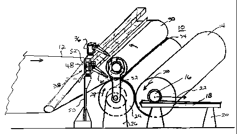
Referring to Figure 1 there is shown a winder 10 for winding a web
12 into rolls 14 in successive cores 16. The winder 10 is preferably part
of a winding section in a paper making machine. The web 12 is
preferably a paper web or paperboard. The roll 14 is supported by its core
ao 16 on rails 18 (one shown) supported by stands 20. As the diameter of the
wound web on roll 14 increases, the core 16 moves along rails 18 in the
direction of arrow 22. The web 12 is driven by driving reel drum 24 onto
the core 16. The driving reel drum 24 is also shown in driving
engagement with roll 14 wound about core 16. The driving reel drum 24
.~s is mounted on stands 26 and driven by a motor (not shown). The
direction of rotation of driving reel drum 24 is shown by arrow 27 which
results in the roll 14 rotating in the direction shown by arrow 28.
CA 02227113 1998-O1-15
-7- CWC-120
The winder 10 is shown with an empty core 30 loaded and
supported by transfer arm mechanism 32 onto the driving reel drum 24. It
should be understood that for the purposes of illustration, only arm
mechanism 32 is shown and that some other apparatus is usually required
s to lc>wer the empty core 30 into the position shown. The empty core 30 is
typically lowered into position prior to web turn up. The transfer arm
mechanism 32 is a part of the changing apparatus for cutting and
transferring the web 12 from a full roll, as illustrated by roll 14, to the
empty core 30. The transfer arm mechanism 32 is controlled to rotate in a
io clockwise direction to place the empty core 30 on the rails 18 after the
web 12 has been cut and turned up onto the empty core 30. Prior to
lowering the empty core 30 to its normal winding position onto rails 18,
the roll 14 is moved away from the driving reel drum 24 along rails 18.
As the empty core is lowered into the initial winding position
i s shown in Figure 1, the empty core 30 is accelerated by auxiliary means
(not shown) and brought into driving contact with the driving reel drum
32. Once the empty core 30 engages the driving reel drum 24 at nip 34,
the cutting of the web 12 to bring about its turn-up onto the empty core 30
is initiated.
a:o The roll changing apparatus for cutting the web 12 includes
stationary auxiliary nozzle 36 and water jet cutting device 38 which
includes at least one nozzle 40.
Stationary nozzle 36 is located upstream of nip 34 on the same side
of the web 12 as the empty core 30. The stationary nozzle 36 directs a
as low atomized adhesive fluid stream against an edge portion of the empty
core 12. The adhesive fluid is a water based fluid preferably containing
amounts of glue or adhesive materials. The nozzle 36 directs the adhesive
CA 02227113 1998-O1-15
-8- CWC-120
stre;~m against the edge of the empty core 30 adjacent or overlapping with
the initial lead in tip to be cut from the web 12 by a water jet cutting
device 38.
Referring to Figure 2, the portion of the empty core 30 where the
s adhesive fluid is directed is shown at 42. This is an area of about 6 to 8
inches from the edge of the web 12. The stationary mounting of the
auxiliary nozzle 36 is illustrated to be mounted on the beam 48 of the
water jet cutting device 38. It should be understood that the auxiliary
nozzle 36 may be mounted directly to the floor by a separate supporting
i o structure.
The water jet cutting device 38 has a beam 48 supported by arm 50
above the floor (or by other suitable means). The water jet cutting device
38 includes a carriage 52 movable lengthwise along beam 48 across the
width of empty core 30 and web 12. The water jet cutting device 38
Is includes a high pressure water jet nozzle 40 that directs a water jet at
the
top surface of web 12. The nozzle 40 is in position on the same side of
the web 12 as the empty core 30 and upstream of the nip 34 so as to direct
the water jet against the web 12, supporting surface of the reel driving
drum 24 and into nip 34 to cut the web. The water jet is directed towards
2 o the web 12 at a relatively shallow angle to backsplash water from the
surface of web 12 onto the surface of the empty core 30. The wetted
surface of the empty core 30 causes the cut leading tip 44 (Figure 2) of
web 10 to turn-up onto the empty core 30 by adhesion. Further, the
adhesive temporary sprayed onto the empty core 30 assists in the turn-up
2s of the tip 44 onto the empty core 30.
Once turn-up has been initiated, the water jet nozzle 40 moves with
carriage 52 across the rail or beam 48 as indicated by arrow 53.. This cuts
CA 02227113 1998-O1-15
-9- CWC-120
a tail 46 in pattern shown in Figure 2 across the web 12 thereby severing
the web 12 from the existing roll 14.
While the preferred embodiment of the present invention utilizes an
auxiliary low pressure stationary nozzle 36 to glue a portion of the surface
s of the empty core 30 to effect turn-up of the leading tail 44 cut into the
web 12, if should be understood that it is contemplated to be within the
realm of the present invention to rely on the backsplash created at the nip
34 to wet the empty core 30 and result in the web 12 adhering to the
empty core 30 as the cut leading tip is pressed through nip 34.
~ o The lateral cross cut as shown in Figures 1 and 2 is suitable for cuts
across a web of slower paper machines running at web speeds of 2,200 to
2,500 feet per minute.
In higher speed machines it may be better to perform a cross cut by
two independently movable water jet nozzles 40, 41 as shown in Figure 3
i s providing the cutting pattern 66 of Figure 4. In this embodiment, a
central tip 45 is cut into the web. The auxiliary nozzle is located above
the center of the empty core 30 to spray adhesive onto the core and assist
in tl~rn up of the tip onto the core 30 at 43. The cutting nozzles 40, 41
may already be accelerating across the web 12 with the water jet being
a:o turned on near the location of the central tip 45 cutting the web 12
ourivardly from the central tip 45. By using two cutting nozzles 40, 41,
the 'time to cut the web is reduced, reducing the number of turns of non-
usable web onto the core prior to the web cut being completed.