Sélection de la langue

Search

Sommaire du brevet 2227714 

Énoncé de désistement de responsabilité concernant l'information provenant de tiers

Une partie des informations de ce site Web a été fournie par des sources externes. Le gouvernement du Canada n'assume aucune responsabilité concernant la précision, l'actualité ou la fiabilité des informations fournies par les sources externes. Les utilisateurs qui désirent employer cette information devraient consulter directement la source des informations. Le contenu fourni par les sources externes n'est pas assujetti aux exigences sur les langues officielles, la protection des renseignements personnels et l'accessibilité.

Disponibilité de l'Abrégé et des Revendications

L'apparition de différences dans le texte et l'image des Revendications et de l'Abrégé dépend du moment auquel le document est publié. Les textes des Revendications et de l'Abrégé sont affichés :

  • lorsque la demande peut être examinée par le public;
  • lorsque le brevet est émis (délivrance).
(12) Demande de brevet: (11) CA 2227714
(54) Titre français: DISPOSITIF SERVANT A MONTER UNE COMPOSANTE
(54) Titre anglais: COMPONENT MOUNTING DEVICE
Statut: Réputée abandonnée et au-delà du délai pour le rétablissement - en attente de la réponse à l’avis de communication rejetée
Données bibliographiques
(51) Classification internationale des brevets (CIB):
  • H05K 3/30 (2006.01)
  • H01R 13/66 (2006.01)
(72) Inventeurs :
  • WESTLUND, KENT A. (Canada)
(73) Titulaires :
  • THE WHITAKER CORPORATION
(71) Demandeurs :
  • THE WHITAKER CORPORATION (Etats-Unis d'Amérique)
(74) Agent: SMART & BIGGAR LP
(74) Co-agent:
(45) Délivré:
(22) Date de dépôt: 1998-01-21
(41) Mise à la disponibilité du public: 1998-08-20
Licence disponible: S.O.
Cédé au domaine public: S.O.
(25) Langue des documents déposés: Anglais

Traité de coopération en matière de brevets (PCT): Non

(30) Données de priorité de la demande:
Numéro de la demande Pays / territoire Date
08/803,294 (Etats-Unis d'Amérique) 1997-02-20

Abrégés

Abrégé français

L'invention comporte un dispositif de support constitué d'un corps doté d'une partie centrale et de deux pattes élastiques partant de la partie centrale dans une première direction. Les pattes comportent des éléments engageant une carte de circuits imprimés. Le corps est muni d'un bras à crochet qui va dans une deuxième direction à partir de la partie centrale pour s'engager dans une composante. Le bras crochet comporte une première partie qui va dans la deuxième direction et une partie déviée par flexion vers la partie centrale. La partie déviée par flexion peut être déviée vers la première partie pour permettre le passage par un trou de fixation et elle comporte une extrémité engageant la composante pour la fixer au corps. Ce dermier maintient la composante sur la carte de circuits imprimés.


Abrégé anglais


The invention comprises a holding device having a
body member with a central portion and two resilient
legs extending therefrom in a first direction. The legs
have engagement members for engaging a circuit board.
The body member has a hook arm extending in a second
direction from the central portion for engagemtne with a
component. The hook arm has a first portion extending
in the second direction and a resiliently deflectable
portion extending towards the central portion. The
resiliently deflectable portion being deflectable
towards the first portion to allow passage through a
mounting hole and has an end for engaging the component
to secure the body member thereto. The body member
secures the component to the circuit board.

Revendications

Note : Les revendications sont présentées dans la langue officielle dans laquelle elles ont été soumises.


What is Claimed is:
1. A holding device, comprising:
a body member having a central portion with two
resilient legs extending therefrom in a first direction,
the legs having engagement members for engaging a
circuit board, the body member having a hook arm
extending in a second direction from the central portion
for engagement with a component, the hook arm having a
first portion extending in the second direction and a
resiliently deflectable portion extending towards the
central portion, the resiliently deflectable portion
being deflectable towards the first portion to allow
passage through a mounting hole, and having an end for
engaging the component to secure the body member
thereto, whereby the body member secures the component
to the circuit board.
2. The holding device of claim 1, wherein the body
member is substantially planar.
3. The holding device of claim 1, wherein the
resilient legs have straight portions which are to be
received within the mounting hole on the component.
4. The holding device of claim 3, wherein the
resilient legs have stop members to engage the component
and secure the holding device to the component.
5. The holding device of claim 1, wherein the
resilient legs have board engaging portions, the board
engaging portions having angled surfaces to provide for
deflection of the legs during insertion of the body
member into a mounting hole on the circuit board and
angled surfaces for engaging a side of the circuit board
for securing the body member to the circuit board.
6. The holding device of claim 1, wherein the
first portion of the hook arm has an end opposite to the
central portion, the resiliently deflectable portion
extending from the end of the first portion.

Description

Note : Les descriptions sont présentées dans la langue officielle dans laquelle elles ont été soumises.

CA 02227714 1998-01-21
16856 CA
COMPONENT MOUNTING DEVICE
This invention is related to a mounting device for
loc]~ing or securing a component such as an electrical
connector to a circuit board.
There are numerous ways of securing an electrical
connector to a circuit board. For example, the
connector may be provided with mounting flanges
hav.ing bores that align with corresponding apertures on
the circuit board. Threaded fasteners can be extended
through the bore and the board aperture.
In other arrangements, such as disclosed in U.S.
Patent 5,145,407, a holding device is inserted through
an opening in a component and has resilient legs for
engaging the circuit and securing the circuit board to
the component. The mounting device includes one portion
having a latch extending angularly from the plane of the
moun,ting device. Further, the mounting device has barbs
for securing the mounting device to the component. The
mounting device also has legs with a first portion which
are tapered outwardly and a second portion which is
tapered inwardly to provide spring action transverse to
the plane of the mounting device and to engage a hole in
the circuit board.
In mounting components to boards, it would be
desirable to provide a simple snap in board which can be
easily made. It is also desirable to provide a secure
connection between the component and the board.
The invention comprises a holding device having a
body member with a central portion and two resilient
legs extending therefrom in a first direction. The legs
have engagement members for engaging a circuit board.
The body member has a hook arm extending in a second
direction from the central portion for engagemtne with a
component. The hook arm has a first portion extending
in the second direction and a resiliently deflectable
portion extending towards the central portion. The
resiliently deflectable portion being deflectable

CA 02227714 1998-01-21
16856 CA
towards the first portion to allow passage through a
mounting hole and has an end for engaging the component
to secure the body member thereto. The body member
secures the component to the circuit board.
The invention further comprises a boardlock device
having a substantially planar member with a central
port:ion. Two resilient legs extend from the central
port:ion in a first direction. A hook arm extends from
the central portion in a second direction. The hook arm
has a first section extending from the central portion
in a second direction. The hook arm has a resilient arm
extending from the first section towards the central
port:ion. The resilient arm provides a snap action to
secure the boardlock device into a mounting hole on a
component to be mounted to a board. The boardlock
device secures the component a circuit board.
The invention further comprises a holding device
for securing two components together. The first
component has a first mounting hole and the second
component having a second mounting hole. The holding
device has a central portion with two resiliently
deflectable legs extending therefrom. The legs have
securing members for engaging and securing the second
mounting hole of the second component. A hook arm
extends from the central portion for engaging the first
mounting hole on the first component. The hook arm has
a first portion extending away from the central portion
and a second portion extending towards the central
portion. The second portion is a resiliently
deflectable arm which is deflectable towards the first
portion. The holding device secures the first and the
second components together.
An embodiment of the present will now be described
with reference to the accompanying drawings, in which:
Figure 1 is a cross sectional view of a component
and the holding device of the present invention;

CA 02227714 1998-01-21
16856 CA
Figure 2 is a view similar to Figure 1 showing the
insertion of the holding device into the component;
Figure 3 is a view similar to Figure 2 showing the
holding device secured within the component;
Figure 4 is a cross sectional view of the component
and the board with the holding device of the present
invention;
Figure 5 is a view similar to Figure 4 showing the
engagement of the holding device with the board;
Figure 6 is a view similar to Figure S showing the
housing device secured to the board; and
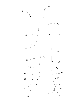
Figure 7 is a side plane view of the holding device
of t:he present invention.
The present invention is directed to a hold down
device for securing two components together. The hold
down, device can be a boardlock, for example, or it can
be used to secure varying components together. The
comp~onent 10 can be, for example, an electrical
connector. Furthermore, the other component could be a
circuit board 14 or some type of device to which the
component 10 is to be secured.
The component 10 has an opening 12 into which the
boardlock 20 is received. Furthermore, the printed
circuit board 14 has an opening 16 also in which the
boardlock will be secured. The component 10 has a top
surface 13 and a bottom mating surface 15. The circuit
board 14 has a top surface l9 onto which the component
10 will be received and it has a bottom surface 17.
Boardlock 20 is an essentially planar device which
is stamped and formed from sheet metal. The boardlock
20 has a central portion 22. The central portion runs
essentially parallel to the top surface l9 of the
circuit board 14 and the mating face 15 of the component
lO. Extending upwardly from the central portion 22, as
shown in Figure 7, is a hook arm 24. The hook arm 24
includes a first portion 26 which extends essentially
straight up and down from the central portion 22. The

16856 CA CA 02227714 1998-01-21
hook arm 24 then has a bent portion 28 or a rounded over
por1:ion and finally a resiliently deflectable portion 30
which is extending back toward the central portion 22.
The hook arm 24 forms a cantilevered arm wherein the
resi.liently deflectable portion 30 can be pushed
inwardly towards the first portion 26 but in its normal
stat:e extends slightly outwardly from the first portion
26 and the central portion 22. The resiliently
deflectable portion 30 has an end surface 32.
The boardlock 20 also has two downwardly extending
legc 40, as shown in Figure 1. The legs 40 are spaced
apart from each other and are resiliently deflectable
towards each other. Each of the downwardly extending
legs 40 has a straight portion 42. At the end of the
straight portion 42, in the mid portion of each of the
legs 40, is stop member 44. Extending beyond the stop
member are boardlock portions 46. Each of the boardlock
portions 46 have angled surfaces 47, 49 which converge
toward point 48.
In operation, the upper portion of the boardlock
20, as shown in Figure 1, is first inserted into the
mounting hole 12 on the component 10 and secured
therein. The width of the hook arm 24 is slightly
larger than that of the mounting hole 12, therefore when
the boardlock is inserted, the second portion 30 of the
hook arm will be resiliently deflected to pass
therethrough. The straight portions 42 of legs 40 are
dimensioned to be received within the mounting hole 12
without deflection. Upon complete insertion of the
boardlock 20, as seen in Figure 3, the resiliently
deflectable portion 30 of the hook arm 24 will snap or
resile outwardly thereby having the end 32 of the hook
arm engage a top surface 13 of the component.
Furthermore, stop members 44 will engage the bottom
surface 15 thereby preventing the boardlock from moving
further through the mounting hole 12. The engagement of
the hook arm 24 with 'he top surface 13 and the stop

16856 CA CA 02227714 1998-01-21
members 44 with the bottom surface 15 serve to keep the
boardlock captivated within the mounting hole 12.
An alternative arrangement has the width of the
straight portions 42 of legs 40 slightly wider than the
width of the mounting hole 12. As the boardlock 20 is
inserted into the mounting hole 12, the straight
portions 42 of the legs 40 will skive the sides of the
mounting hole 12 forming a groove, not shown, into which
the boardlock will be received. The groove will keep
the boardlock from rotating within the mounting hole 12.
The stop members 44 will engage the bottom surface 15 to
keep the boardlock 20 captivated within the mounting
hole 12.
The boardlock 20 is secured to the component 10 so
that is ready to be mounted and secured to the board 14.
When the component is mounted, the boardlock portion 46
of the legs 40 first engage the mounting hole 16. The
boardlock portion of the boardlock is wider than the
mounting hole 16. When the angled surfaces 49 engage
the mounting hole 16, the legs 40 are deflected inwardly
towards each other. When the point 48 is received
beyond the mounting hole 16, the legs 40 will resile
back towards their initial position and the angled
surfaces 47 will engage the bottom surface 17 of the
circuit board 14 and secure the component 10 to the
circuit board 14 with the mating face lS of the
comp~onent 10 against the top surface 19 of the circuit
board 14.
The engagement of the angled surfaces 47 and the
poin,ts 48 on the bottom surface of the printed circuit
board will secure the connector for the component to the
printed circuit board. The use of angled surfaces 47
allow for differences in the width of the board 14
because the board 14 can be engaged at any position
along the angled surfaces 47.
In the preferred embodiment the boardlock 20 is

CA 02227714 1998-01-21
16856 CA
formed from continuous sheet metal stock of a sufficient
thickness and hardness to serve as a holding device by
virtue of the deflectable legs and the hook arm.
Materials such as brass, phosphor bronze, or stainless
stee:L may be employed. In one example, the thickness of
the material is 0.017 inches. However, this thickness
can be varied depending on the particular need of the
boardlock. The dimension of the mounting holes are
suff:iciently large to allow deflection of the
deflectable legs and the arm respectively to provide an
elastic spring action holding the legs, and therefore
the points, in engagement with the surface of the
prinl_ed circuit board and the hook arm in engagement
with the surface of the component.
It is felt that the boardlock of the present
invention and many of its attendant advantages will be
understood from the foregoing description. It is
appa:rent that varies changes may be made in the form,
construction, and arrangement of parts thereof without
departing from the spirit or scope of the invention, or
sacrificing all of its material advantages.

Dessin représentatif
Une figure unique qui représente un dessin illustrant l'invention.
États administratifs

2024-08-01 : Dans le cadre de la transition vers les Brevets de nouvelle génération (BNG), la base de données sur les brevets canadiens (BDBC) contient désormais un Historique d'événement plus détaillé, qui reproduit le Journal des événements de notre nouvelle solution interne.

Veuillez noter que les événements débutant par « Inactive : » se réfèrent à des événements qui ne sont plus utilisés dans notre nouvelle solution interne.

Pour une meilleure compréhension de l'état de la demande ou brevet qui figure sur cette page, la rubrique Mise en garde , et les descriptions de Brevet , Historique d'événement , Taxes périodiques et Historique des paiements devraient être consultées.

Historique d'événement

Description Date
Inactive : CIB de MCD 2006-03-12
Le délai pour l'annulation est expiré 2003-01-21
Demande non rétablie avant l'échéance 2003-01-21
Réputée abandonnée - omission de répondre à un avis sur les taxes pour le maintien en état 2002-01-21
Demande publiée (accessible au public) 1998-08-20
Symbole de classement modifié 1998-05-04
Inactive : CIB attribuée 1998-05-04
Inactive : CIB en 1re position 1998-05-04
Exigences de dépôt - jugé conforme 1998-04-20
Inactive : Certificat de dépôt - Sans RE (Anglais) 1998-04-20
Demande reçue - nationale ordinaire 1998-04-16

Historique d'abandonnement

Date d'abandonnement Raison Date de rétablissement
2002-01-21

Taxes périodiques

Le dernier paiement a été reçu le 2000-12-21

Avis : Si le paiement en totalité n'a pas été reçu au plus tard à la date indiquée, une taxe supplémentaire peut être imposée, soit une des taxes suivantes :

  • taxe de rétablissement ;
  • taxe pour paiement en souffrance ; ou
  • taxe additionnelle pour le renversement d'une péremption réputée.

Veuillez vous référer à la page web des taxes sur les brevets de l'OPIC pour voir tous les montants actuels des taxes.

Historique des taxes

Type de taxes Anniversaire Échéance Date payée
Taxe pour le dépôt - générale 1998-01-21
Enregistrement d'un document 1998-02-19
TM (demande, 2e anniv.) - générale 02 2000-01-21 1999-12-15
TM (demande, 3e anniv.) - générale 03 2001-01-22 2000-12-21
Titulaires au dossier

Les titulaires actuels et antérieures au dossier sont affichés en ordre alphabétique.

Titulaires actuels au dossier
THE WHITAKER CORPORATION
Titulaires antérieures au dossier
KENT A. WESTLUND
Les propriétaires antérieurs qui ne figurent pas dans la liste des « Propriétaires au dossier » apparaîtront dans d'autres documents au dossier.
Documents

Pour visionner les fichiers sélectionnés, entrer le code reCAPTCHA :


Pour visualiser une image, cliquer sur un lien dans la colonne description du document. Pour télécharger l'image (les images), cliquer l'une ou plusieurs cases à cocher dans la première colonne et ensuite cliquer sur le bouton "Télécharger sélection en format PDF (archive Zip)" ou le bouton "Télécharger sélection (en un fichier PDF fusionné)".

Liste des documents de brevet publiés et non publiés sur la BDBC .

Si vous avez des difficultés à accéder au contenu, veuillez communiquer avec le Centre de services à la clientèle au 1-866-997-1936, ou envoyer un courriel au Centre de service à la clientèle de l'OPIC.


Description du
Document 
Date
(aaaa-mm-jj) 
Nombre de pages   Taille de l'image (Ko) 
Dessin représentatif 1998-09-08 1 6
Page couverture 1998-09-08 1 46
Description 1998-01-21 6 266
Dessins 1998-01-21 2 47
Abrégé 1998-01-21 1 20
Revendications 1998-01-21 1 46
Courtoisie - Certificat d'enregistrement (document(s) connexe(s)) 1998-04-20 1 116
Certificat de dépôt (anglais) 1998-04-20 1 163
Rappel de taxe de maintien due 1999-09-22 1 114
Courtoisie - Lettre d'abandon (taxe de maintien en état) 2002-02-18 1 182
Rappel - requête d'examen 2002-09-24 1 116