Note : Les descriptions sont présentées dans la langue officielle dans laquelle elles ont été soumises.
CA 02227856 1998-O1-27
DOWNHOLE PRESSURE RELIEF VALVE FOR WELL PUMP
Technical Field
This invention relates in general to submersible well pump installations
and particularly to a downhole wireline retrievable pressure relief valve for
a
progressive cavity pump.
Background Art
One type of well pump in use is a progressing cavity pump. A
progressing cavity pump has an elastomeric stator containing double helical
cavities
along its length. A metal rotor with a helical contour rotates within the
stator in an
orbital motion. This produces pumping action for pumping fluids.
In one type of installation, the progressing cavity pump is located at the
lower end of a string of tubing which is suspended within casing from a
wellhead.
The pump is driven by a downhole electrical motor and discharges well fluid
through
the tubing that flows to the surface. The wellhead at the surface has various
valves for
1 S controlling the well.
This type of pump will become damaged if the discharge pressure
becomes too high. That is, if the tubing becomes restricted such as one of the
wellhead valves being inadvertently closed, the pump will not be able to pump
against
this closed valve without damage occurring. As a result, pressure relief
valves are
installed on the surface for relieving the pressure in the tubing if it
exceeds a selected
maximum. While workable, disposal of the well fluid discharged out the
pressure
relief valve needs to be handled. Additional piping for the pressure relief
valve and
the disposal is needed. The piping is subject to leakage and adds expense to
the
assembly.
A hydraulically operated valve for draining the tubing of well fluid has
also been utilized at the lower end of the string of tubing. When the operator
wishes to
pull the string of tubing, he will open the valve, which causes fluid in the
tubing to
flow out the lower end of the tubing as the string of tubing is being pulled
from the
well. This allows the tubing string to be pulled dry. Excess pressure
encountered in
the tubing will also cause this type of valve to open. However, this type of
valve does
not move back to a closed position once the excessive pressure problem is
removed.
In order to again close the valve, the operator has to pull the string of
tubing and the
pump to the surface. This requires a workover rig and is time consuming. The
process of pulling tubing is costly.
CA 02227856 2000-06-O1
-2-
Disclosure of the Invention
In this invention, a progressing cavity pump assembly is installed with
a pressure relief valve that is located in the string of tubing which does not
require
resetting at the surface. The relief valve is located above the pump,
preferably near
the surface, and contains a valve element that is urged by a spring against a
valve seat.
When the tubing pressure becomes excessive, the valve element moves to an open
position, venting the fluid in the tubing to the casing. When the excessive
pressure
problem is rectified, and the pressure drops below the preset maximum, the
valve will
close, enabling production to continue.
to In the preferred embodiment, the valve assembly is made up of two
main parts, a stationary body and a retrievable valve sub. The body secures
into the
string of tubing while the tubing is being installed and has a flow passage
for flow
through the tubing. The body also has a discharge port that leads to the
exterior of the
tubing. The valve sub and the body having mating stab connector portions. The
15 valve sub contains a valve seat, a spring and a valve element. The valve
sub has a
profile on its upper end which allows it to be retrieved through the tubing,
leaving the
valve body downhole. When the valve sub and valve body make up with the stab
connector portions, the downstream side of the valve seat will communicate
with the
discharge port in the valve body.
2o Accordingly, in one aspect the present invention provides in a well
having a string of tubing within casing, a pump secured to the tubing for
pumping
fluid through the bore of the tubing, an improved pressure relief valve for
the pump,
comprising:
a valve assembly mounted to the string of tubing of the pump, wherein
25 the tubing string has an axis, the valve assembly positioned substantially
in-line with
said tubing string axis and having a main flow passage therethrough for
conveying
fluid being pumped by the pump through the tubing;
a valve seat in the valve assembly, having an upstream end and a
downstream end, said valve seat positioned substantially in line with said
tubing
3o string axis and the upstream end being in fluid communication with the bore
of the
tubing;
CA 02227856 2000-06-O1
-2a-
a spring-biased valve element carried by the valve assembly and urged
by the spring against the downstream end of the valve seat to maintain the
valve seat
closed; and
a discharge passage in the valve assembly, in fluid communication
with the downstream end of the valve seat and leading to the exterior of the
tubing for
discharging into the casing fluid flowing through the valve seat in the event
that
pressure in the bore of the tubing reaches a level to cause the valve element
to open
the valve seat.
In another aspect of the present invention there is provided in a well
1 o having a string of tubing within casing, a pump secured to the tubing for
pumping
fluid through the bore of the tubing, an improved pressure relief valve for
the pump,
comprising:
a body having a longitudinal axis and mounted stationarily into the
string of tubing above the pump, the body having an lower end and an upper
end, the
15 body having an axial stab connector portion;
a main flow passage extending from the lower end to the upper end of
the body for conveying fluid being pumped by the pump through the tubing;
a valve sub having an axial stab connector portion which mates with
the axial stab connector portion of the body;
2o a profile on an upper end of the valve sub for engagement with a
wireline tool for lowering the valve sub through the string of tubing and into
engagement with the body with the stab connector portions;
a valve seat in the valve sub, having an upstream end and a
downstream end;
25 a spring-biased valve element carried by the valve sub and urged by
the spring against the downstream end of the valve seat to maintain the valve
seat
closed, the upstream end of the valve seat being in fluid communication with
the bore
of the tubing for applying pressure to the valve element, tending to cause the
valve
element to move to an open position; and
3o a discharge passage in the body in fluid communication with the
downstream end of the valve seat and leading to the exterior of the tubing for
CA 02227856 2000-06-O1
-2b-
discharging into the casing fluid flowing through the valve seat in the event
of
excessive pressure opening the valve seat.
In yet another aspect of the present invention there is provided a
pressure relief valve for a pump suspended in casing in a well on a string of
tubing,
comprising:
a body having a longitudinal axis, a lower end and an upper end, the
body having threads on its upper and lower ends for securing the body into the
string
of tubing;
a central receptacle extending axially downward from the upper end of
1 o the body;
a main flow passage extending from the lower end to the upper end of
the body and offset from the receptacle for conveying fluid being pumped by
the
pump through a bore of the tubing;
a valve sub having a mandrel which stabs sealingly and releasably into
15 the receptacle;
a profile on the valve sub for engagement with a wireline tool to lower
and retrieve the valve sub through the tubing;
a valve seat in the valve sub, having an upstream end and a
downstream end;
2o a spring-biased valve element carried by the valve sub and urged by
the spring against the downstream end of the valve seat to maintain the valve
seat
closed;
an upstream passage in the valve sub leading from the upstrea.~m end of
the valve seat to the exterior of the valve sub for communicating pressure of
the bore
25 of the tubing to the valve element to tend to cause it to open the valve
seat;
a bypass passage in the mandrel extending from the downstream end of
the valve seat to the exterior of the mandrel for communicating the downstream
end
of the valve seat with the receptacle of the body; and
a discharge passage in the body leading from the receptacle to the
3o exterior of the tubing for discharging into the casing fluid flowing
through the valve
seat in the event of excessive pressure opening the valve seat.
CA 02227856 2000-06-O1
-2c-
In still yet another aspect of the present invention there is provided a
method for relieving excess pressure that may occur at a discharge of a well
pump
suspended on a string of tubing within casing, comprising:
mounting a pressure relief valve in the string of tubing downstream
from the pump, the pressure relief valve being positioned within the outer
diameter of
the tubing string and having a movable valve element urged by a spring against
a
valve seat;
applying pressure in the string of tubing due to fluid being pumped by
the pump to the pressure relief valve; and
1 o if the pressure in the string of tubing exceeds a selected amount,
causing the valve element to move away from the valve seat, compressing the
spring
and venting the pressure in the tubing through the pressure relief valve to
the casing.
Brief Description of Drawings
15 An embodiment of the present invention will now be described more
fully with reference to the accompanying drawings in which:
Figure 1 is a schematic side view, partially sectioned, illustrating a
progressing cavity pump assembly constructed in accordance with this
invention;
Figures 2a and 2b in combination are an enlarged sectional view of the
2o pressure relief valve portion of the pump assembly of Figure 1 and showing
the valve
in a closed position, but not showing the casing;
Figure 3 is a further enlarged sectional view of the pressure relief valve
of Figures 2a and 2b, showing the pressure relief valve in an open position
and
showing the casing; and
25 Figures 4a and 4b in combination are a sectional view of the pressure
relief valve of Figures 2a and 2b, showing the valve sub being retrieved from
the
valve body, but not showing the casing.
CA 02227856 1998-O1-27
-3-
Best Mode for Carrying Out the Invention
Refernng to Figure 1, well 11 has a casing 13 supported by a wellhead
14 at the surface. A string of tubing 1 S is suspended by wellhead 14 in
casing 13. A
pump 17 is mounted to a lower end of tubing 15. Pump 17 is a conventional
S progressing cavity type, having a metal helical rotor that is rotated within
an
elastorneric stator.
An adapter 19 connects the lower end of pump 17 to a seal section 21.
A flexible shaft (not shown) is located in adapter 19 for accommodating the
orbital
motion of the helical shaft of pump 17. Seal section 21 has a thrust bearing
(not
shown) for absorbing downthrust. A gear reducer 23 locates below seal section
21
and is connected to an electrical motor 25. Gear reducer 23 reduces the speed
of
motor 25. Motor 25 is filled with a lubricant. Seal section 21 equalizes the
pressure
of the lubricant in motor 25 with the exterior in casing 13. An electrical
power cable
27 extends from the surface alongside tubing 15 for supplying electrical power
to
motor 25. In the embodiment shown, a pressure and temperature sensor 29 is
mounted to the lower end of motor 25. When driven by motor 25, pump 17 will
pump
fluid through tubing 15 to wellhead 14. If a valve at wellhead 14 is
inadvertently
closed, the discharge pressure of pump 17 will build, eventually damaging pump
17,
unless otherwise relieved. A pressure relief valve 31 is located above pump
17,
ideally just below wellhead 14, for preventing the discharge pressure from
exceeding
a selected maximum. Pressure relief valve 31 will vent pressure to the
exterior of
tubing 15 within casing 13.
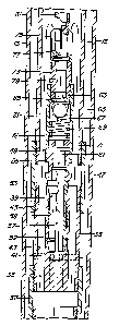
Refernng to Figures 2a and 2b, pressure relief valve 31 includes a body
33 which is a tubular member having a set of threads 35 on its lower end.
Threads 35
secure to a coupling 37, which connects to tubing 15. Body 33 has an axial
central
receptacle 39 that extends downward from the upper end of body 33, but
terminates
above the lower end of body 33. Receptacle 39 is a cylindrical bore and serves
as one
portion of a stab connector. A plurality of discharge passages 41 lead
radially from
the lower end of receptacle 39 to the exterior of body 33 within casing 13. A
plurality
of main flow passages 43 extend axially through body 33 from the lower end to
the
upper end. Main flow passages 43 are offset from and spaced in an array around
receptacle 39. Main flow passages 43 allow fluid flowing upward from pump 17
to
flow through. Body 33 also has a set of threads 45 on its upper end which
secure to
tubing 15 through a coupling 47.
CA 02227856 1998-O1-27
-4-
A valve sub 49 forms a second portion of the pressure relief valve
assembly. Valve sub 49 includes a tubular member 51 that locates within tubing
15.
A mandrel 53 connects to tubular member 51 by an adapter bushing 55 and
extends
downward. Mandrel 53 is hollow and has slits 57 in its lower end, forming a
collet.
S Mandrel 53 serves as a second portion of a stab connector for tight sliding
reception
within receptacle 39. A seal 58 seals mandrel 53 to receptacle 39. Mandrel 53
has a
locking shoulder 59 near its lower end which snaps into a recess 60 (Figs. 4a
and 4b)
located at the base of receptacle 39. A bypass passage 61 extends axially
through
mandrel 53 and adapter 55.
A valve seat 63 is mounted in an upper portion of tubular member 51.
Valve seat 63 has an upstream end which faces upward and a downstream end
which
faces downward. A valve element or ball 65 engages the downstream end of valve
seat 63 to close valve seat 63. Ball 65 is urged upward into engagement with
valve
seat 63 by a spring 69 which engages ball 65 with a spring retainer 67. An
adjusting
ring 71 located at the base of spring 69 enables the compression of spring 69
to be
changed to provide the desired force.
A tubular plug 73 is secured to the upper end of tubular member 51.
Plug 73 has a cage 75 mounted to its upper end which has slots 77 to admit
fluid into
tubing 15. Slots 77 communicate with a communication passage 79 that extends
axially through plug 73. Communication passage 79 leads to the upstream end of
valve seat 63.
A fishing neck 81 is mounted to the upper end of cage 75. Neck 81 has
a profile 82 on its exterior made up of a plurality of conical grooves.
Profile 82 is
adapted to be engaged by a running tool 84 (Figs. 4a and 4b) of a conventional
nature.
Running tool 84 may be of a wireline type and is shown with dotted lines as it
may be
of a variety of types and is commercially available.
In operation, the assembly will be installed as shown in Figures 1, 2a
and 2b. During normal pumping, motor 25 will drive pump 17 to cause fluid to
be
discharged up tubing 15. The fluid flows through main flow passages 43 and
through
tubing 1 S to wellhead 14, as indicated by arrows 83 in Figures 2a and 2b. The
pressure of the well fluid in tubing 15 at pressure relief valve 31 will be in
communication with the upstream end of valve seat 63. This pressure acts
through
communication passage 79 on ball 65, tending to push it away from valve seat
63 to
an open position. Under normal operations, the force of spring 69 is
sufficient to
prevent ball 65 from moving downward to an open position.
CA 02227856 1998-O1-27
-$-
If excessive discharge pressure is encountered, such as due to an
inadvertently closed valve in wellhead 14, pump 17 will begin building up the
discharge pressure. Refernng to Figure 3, once the force caused by the
pressure on
ball 65 exceeds the force of spring 69, ball 65 will move to an open position
as shown,
compressing spring 69. As indicated by the arrows 85, fluid will flow downward
through valve seat 63, past ball 65, through bypass passage 61 and out
discharge
passages 41. The well fluid flows into casing 13 and downward to the level of
fluid
within casing 13, normally far below. Pump 17 will continue to operate without
damage because the pressure will not exceed the selected point at which ball
65
moves to the open position. The fluid will circulate in a loop until the
operator
discovers and rectifies the problem.
In the event that repairs need to be made to pressure relief valve 31, it
is not necessary to pull tubing 15. The operator will connect running tool 84
(Figs. 4a
and 4b) to a wireline (not shown) and lower it into the well. Running tool 84
will
slide over neck 81 and engage profile 82. The operator pulls upward with
sufficient
force to dislodge locking shoulders 59 from recess 60 in receptacle 39. Valve
sub 49
is then brought to the surface, leaving valve body 33 downhole. After repair,
the
operator lowers valve sub 49 back into tubing 1 S. Mandrel 53 will stab into
receptacle 39, locking and sealing valve sub 49 to valve body 33.
The invention has significant advantages. The pressure relief valve
limits the discharge pressure of the pump to a safe level. Once the pressure
drops
below the selected level, the valve automatically closes, allowing production
to
continue. Unlike surface pressure relief valves, problems are not encountered
concerning disposal, because the well fluid simply flows back down the casing.
Additional surface piping is not needed with the pressure relief valve. The
two
portions of the pressure relief valve enable the valve seat and ball
components to be
pulled to the surface for maintenance without pulling the tubing.
While the invention has been shown in only one of its forms, it should
be apparent to those skilled in the art that it is not so limited but is
susceptible to
various changes without departing from the scope of invention.