Sélection de la langue

Search

Sommaire du brevet 2228550 

Énoncé de désistement de responsabilité concernant l'information provenant de tiers

Une partie des informations de ce site Web a été fournie par des sources externes. Le gouvernement du Canada n'assume aucune responsabilité concernant la précision, l'actualité ou la fiabilité des informations fournies par les sources externes. Les utilisateurs qui désirent employer cette information devraient consulter directement la source des informations. Le contenu fourni par les sources externes n'est pas assujetti aux exigences sur les langues officielles, la protection des renseignements personnels et l'accessibilité.

Disponibilité de l'Abrégé et des Revendications

L'apparition de différences dans le texte et l'image des Revendications et de l'Abrégé dépend du moment auquel le document est publié. Les textes des Revendications et de l'Abrégé sont affichés :

  • lorsque la demande peut être examinée par le public;
  • lorsque le brevet est émis (délivrance).
(12) Brevet: (11) CA 2228550
(54) Titre français: UNITE DE STOCKAGE DE SUPPORTS PLISSEE EN ACCORDEON ET MUNIE DE POCHES SEPARABLES
(54) Titre anglais: ACCORDION PLEATED MEDIA STORAGE UNIT HAVING SEPARABLE POCKETS
Statut: Périmé et au-delà du délai pour l’annulation
Données bibliographiques
(51) Classification internationale des brevets (CIB):
  • G11B 33/04 (2006.01)
  • G11B 23/023 (2006.01)
(72) Inventeurs :
  • HUNT, RONALD E. (Etats-Unis d'Amérique)
  • WHITEHEAD, VERLON E. (Etats-Unis d'Amérique)
(73) Titulaires :
  • CD3 STORAGE SYSTEMS, INC.
  • CD3 STORAGE SYSTEMS, INC.
(71) Demandeurs :
  • CD3 STORAGE SYSTEMS, INC. (Etats-Unis d'Amérique)
  • CD3 STORAGE SYSTEMS, INC. (Etats-Unis d'Amérique)
(74) Agent: MACRAE & CO.
(74) Co-agent:
(45) Délivré: 2003-11-04
(86) Date de dépôt PCT: 1997-05-23
(87) Mise à la disponibilité du public: 1997-11-27
Requête d'examen: 2002-05-21
Licence disponible: S.O.
Cédé au domaine public: S.O.
(25) Langue des documents déposés: Anglais

Traité de coopération en matière de brevets (PCT): Oui
(86) Numéro de la demande PCT: PCT/US1997/011191
(87) Numéro de publication internationale PCT: WO 1997044788
(85) Entrée nationale: 1998-01-23

(30) Données de priorité de la demande:
Numéro de la demande Pays / territoire Date
08/652,377 (Etats-Unis d'Amérique) 1996-05-23

Abrégés

Abrégé français

L'unité de stockage de supports plissée en accordéon de la présente invention, est constituée d'une bande allongée continue de matière flexible, du type matière filée à base de polyester non tissé. On plie de manière continue en accordéon ladite bande allongée de telle sorte qu'elle détermine de multiples plans superposés possédant chacun au moins une arête solidaire d'un plan adjacent. Puis on effectue une liaison le long de chaque arête d'une paire de plans adjacents, en partant d'une arête commune jusqu'à un point très proche de la ligne médiane de chaque plan, de telle sorte que de multiples poches adjacentes sont constituées. Lorsque l'unité est déployée, lesdites poches sont séparées d'une distance spécifiée, les dimensions des poches n'étant pas modifiées, ce qui facilite considérablement l'introduction et le retrait d'un support d'information.


Abrégé anglais


An accordion pleated media storage
unit is provided which is constructed of a
continuous elongate web of flexible mate-
rial, such as a non-woven polyester spun
material. A continuous zigzag fold of
the elongate web creates multiple overlying
planes, each of which has at least one edge
which is integral with an adjacent plane. A
bond is then formed along each edge of a
pair of adjacent planes, extending from a
common edge to a point just short of the
mid-line of each plane, such that multiple
adjacent pockets are formed which, when
the unit is extended, are separated by a
specified distance and wherein the pocket
dimensions are not altered, greatly enhanc-
ing insertion and retrieval of a storage me-
dia element.

Revendications

Note : Les revendications sont présentées dans la langue officielle dans laquelle elles ont été soumises.


- 12 -
CLAIMS:
1. An accordion pleated extendable media storage unit comprising:
an elongate web of flexible material;
a continuous zigzag fold within said elongate web of flexible
material forming a plurality of overlying planes, each of said plurality of
overlying planes having a bottom edge, two side edges, and a top edge
and wherein at least one of said edges is integral with an adjacent
overlying plane; and
a bond between each two adjacent overlying planes above
each bottom edge which is integral with an adjacent overlying plane, at
each end thereof, terminated at a selected point on each side edge of each
two adjacent overlying planes wherein a plurality of adjacent storage
pockets are formed, which, when said storage unit is extended, expand in
dimension above said selected point while remaining constant in dimension
below said selected point such that a storage media element inserted
within a selected storage pocket will remain centered within said selected
storage pocket during extension of said storage unit.

- 13 -
2. The accordion pleated extendable media storage unit according to
Claim 1, wherein said elongate web of flexible material comprises cloth.
3. The accordion pleated extendable media storage unit according to
Claim 2, wherein said cloth comprises non-woven polyester spun material.
4. The accordion pleated extendable media storage unit according to
Claim 1, wherein each of said overlying planes is generally circular in
shape.
5. The accordion pleated extendable media storage unit according to
Claim 1, wherein said bond is formed utilizing a sonic welding technique.
6. The accordion pleated extendable media storage unit according to
Claim 1, wherein said bond is formed by sewing.
7. The accordion pleated extendable media storage unit according to
Claim 1, wherein said bond is formed utilizing glue.
8. The accordion pleated extendable media storage unit according to
Claim 1, wherein said bond is continuous from each bottom edge which
is integral with an adjacent overlying plane, at each end thereof, to said
selected point on each side edge of each two adjacent overlying planes.

-14-
9. An accordion pleated extendable media storage unit comprising:
an elongate web of flexible material;
a continuous zigzag fold within said elongate web of flexible
material forming a plurality of overlying planes, each of said plurality of
overlying planes having at least one edge which is integral with an
adjacent overlying plane; and
a bond between each two adjacent overlying planes
extending generally from each edge which is integral with an adjacent
overlying plane, at each end thereof, and terminating at a point which is
"X" inches short of the midline of each overlying plane such that a
plurality of fixed dimension adjacent storage pockets are formed, which,
when said storage unit is extended, are separated by "2X" inches.
10. The accordion pleated extendable media storage unit according to
Claim 9, wherein said elongate web of flexible material comprises cloth.
11. The accordion pleated extendable media storage unit according to
Claim 10, wherein said cloth comprises non-woven polyester spun
material.
12. The accordion pleated extendable media storage unit according to
Claim 9, wherein each of said overlying planes is generally circular in
shape.
13. The accordion pleated extendable media storage unit according to
Claim 9, wherein said bond is formed utilizing a sonic welding technique.

- 15 -
14. The accordion pleated extendable media storage unit according to
Claim 9, wherein said bond is formed by sewing.
15. The accordion pleated extendable media storage unit according to
Claim 9, wherein said bond is formed utilizing glue.
16. The accordion pleated extendable media storage unit according to
Claim 9, wherein said bond is continuous from each bottom edge which
is integral with an adjacent overlying plane, at each end thereof, to said
selected point on each side edge of each two adjacent overlying planes.

- 16 -
17. An accordion pleated extendable storage unit comprising:
an elongate web of flexible material;
a continuous zigzag fold within said elongate web of flexible
material forming a plurality of overlying planes, each of said plurality of
overlying planes having a bottom edge, two side edges, and a top edge
and wherein at least one of said edges is integral with an adjacent
overlying plane;
a bond between each two adjacent overlying planes above
each bottom edge which is integral with an adjacent overlying plane, at
each end thereof, terminating at a selected point on each side edge of
each two adjacent overlying planes below the midline of each overlying
plane wherein a plurality of adjacent storage pockets are formed on a first
side of said elongate web of flexible material; and
a bond between each two adjacent overlying planes below
each top edge which is integral with an adjacent overlying pane, at each
end thereof, terminating at a selected point one each side edge of each
two adjacent overlying planes above the midline of each overlying plane
wherein a second plurality of adjacent storage pockets are formed on a
second side of said elongate web of flexible material.
18. The accordion pleated extendable media storage unit according to
Claim 17, wherein said elongate web of flexible material comprises cloth.
19. The accordion pleated extendable media storage unit according to
Claim 17, wherein said cloth comprises non-woven polyester spun
material.

- 17 -
20. The accordion pleated extendable media storage unit according to
Claim 17, wherein each of said overlying planes is generally circular in
shape.
21. The accordion pleated extendable media storage unit according to
Claim 17, wherein said bond is formed utilizing a sonic welding technique.
22. The accordion pleated extendable media storage unit according to
Claim 17, wherein said bond is formed by sewing.
23. The accordion pleated extendable media storage unit according to
Claim 17, wherein said bond is formed utilizing glue.
24. The accordion pleated extendable media storage unit according to
Claim 17, wherein said bond between each two adjacent overlying planes
above each bottom edge which is integral with an adjacent overlying
plane, at each end thereof, terminating at a selected point on each side
edge of each two adjacent overlying planes below the midline of each
overlying plane is continuous from each end of said bottom edge which is
integral with an adjacent overlying plane to said selected point on each
side edge of each two adjacent overlying planes below the midline of each
overlying plane.

- 18 -
25. The accordion pleated extendable media storage unit according to
Claim 17, wherein said bond between each two adjacent overlying planes
below each top edge which is integral with an adjacent overlying plane, at
each end thereof, terminating at a selected point on each side edge of
each two adjacent overlying planes above the midline of each overlying
plane is continuous from each end of said top edge which is integral with
an adjacent overlying plane to said selected point on each side edge of
each two adjacent overlying planes above the midline of each overlying
plane.

Description

Note : Les descriptions sont présentées dans la langue officielle dans laquelle elles ont été soumises.


CA 02228550 1998-01-23
WO 97144788 PCT/US97111191
ACCORDION PLEATED MEDIA STORAGE UNIT HAVING SEPARABLE
POCKETS

CA 02228~0 1998-01-23
WO 97/44788 PCT/US97/11191
- 2 -
BACKGROIJND OF THE INVENTION
3 1. Technical Field:
4 The present invention relates in general to the field of media
5 storage devices and in particular to accordion pleated media storage units
6 capable of storing multiple storage media elements. Still more particularly,
7 the present invention relates to accordion pleated media storage units
8 having separable pockets which do not vary in dimension during
9 separation, which greatly enhances insertion and retrieval of a storage
10 media element.
1 1
12 2. Description of the ~elated Art:
13 Recent advances in both audio and the computer arts have
14 resulted in a proliferation of data which must be stored within portable
15 storage media. Examples of such storage media include computer
16 diskeKes, compact disks, or various removable magnetic storage media.
17 Each of these media stores large amounts of data utilizing either optical or
18 magnetic techniques and each form of media is generally planar in physical
1 9 dimension.
21 While many of the storage media described above are
22 encased within a protective jacket which is integral with the storage
23 media, the compact disk stores large amounts of data representing various
24 voltage levels or digital signals as ultrafine, microscopic pits along a spiral
2~ path in a polymeric substrate, protected by an overlay of another thin
26 polymeric layer. This technique has proven to be greatly superior to
27 conventional phonograph records or tapes for storing digital data and whiie
28 such disks are less vulnerable to scratching, dust and fingerprints the disk
29 must still be protected during transport to avoid damage thereto.

CA 02228~0 1998-01-23
'WO 97144788 PCT/US97/11191
- 3 -
Techniques for storing disk like media have been known in
2 the prior art for decades. US Patent No. 2,261,806 discloses a "carrier
3 case and rack for phonograph records" which is reflective of the state-of-
4 the-art in the 1 930's. This application discloses a plurality of pockets
5 enclosed within a brief case with the pockets linked such that the pockets
6l automatically fold out when the case is opened.
US Patent No. 2,777,574, issued to Brody discloses a holder
9 for phonograph records which is designed as an alternative to the album
10l cover and record jacket arrangement commonly used with phonograph
11 records. Brody attempts to provide means for protecting a record sheath
12 from scratching or frictional wear by providing an outer protective
13 envelope made of plastic material to be placed over the record sheath.
14
More recently, US Patent No. 4,538,730 issued to Wu
16 discloses a storage box for computer floppy disks which includes
17 collapsible storage bags, linked at their edges for extensibility. In this
1~; manner separation is provided between pockets in order to protect the
191 floppy disk.
2CI
21 More recently, US Patent No. 4,762,225 discloses a compact
22 disk guard and carrying system which provides a collapsible enclosure
23, having a mouth portion, extensible side portions, a V-shaped vertex
24 portion and a securable fold over cover which creates an elongated,
2~, substantially rigid, yet foldable substrate which forms a series of pockets
26 within which a compact disk may be stored.
27'
2~, While each of the aforementioned patents demonstrates a
2CJ useful technique for storing a plurality of storage media elements, those
3CI having ordinary skill in the art will appreciate that it would be greatly

CA 02228~0 1998-01-23
WO 97144788 PCTIUS97/11191
- 4 -
1 advantageous to provide an increased storage density within such a
2 storage element, such that a larger number of storage media elements may
3 be stored therein. Further, with increased density of storage, the problems
4 associated with insertion and retrieval of storage media elements is
5 exacerbated. Consequently, it would be desirable to create a storage unit
6 which is designed so as to assist the user in the insertion and retrieval of
7 storage media elements which are stored therein in a high density format.

CA 02228~0 1998-01-23
VO 97/44788 PCT/US97/11191
I SUMMARY OF THE INVENTION
:2
:3 It is therefore one object of the present invention to provide
an improved media storage device.
Ei
6 It is another object of the present invention to provide an
7 improved accordion pleated media storage unit.
9 It is yet another object of the present invention to provide an
1 C) improved accordion pleated media storage unit having separable pockets.
1 1
12 The f~regoing objects are achieved as is now described. The
13 accordion pleated media storage unit of the present invention is
14 constructed of a continuous elongate web of flexible material, such as a
15 non-woven polyester spun fabric. A continuous zigzag fold of the elongate
16 web creates multiple overlying planes, each of which has at least one edge
17 which is integral with an adjacent plane. A bond is then formed along
18 each edge of a pair of adjacent planes, extending from a common edge to
19 a point just short of the mid-line of each plane, such that multiple adjacent20 pockets are formed which, when the unit is extended, are separated by a
21 specified distance and wherein the pocket dimensions are not altered,
22 greatly enhancing insertion and retrieval of a storage media element.
23
24 The above as well as additional objectives, features, and
25 advantages of the present invention will become apparent in the following
26 detailed written description.
27

CA 02228~0 1998-01-23
~NO 97/44788 PCT/US97/11191
BRIEF DESCRIPTION OF THE DRAWINGS
3 The novel features believed characteristic of the invention are
4 set forth in the appended claims. The invention itself, however, as well
5 as a preferred mode of use, further objectives and advantages thereof, will
6 best be understood by reference to the following detailed description of an
7 illustrative embodiment when read in conjunction with the accompanying
8 drawings, wherein:
Figure 1 is a plan view of an elongate flexible web which may
11 be utilized to construct the media storage unit of the present invention;
12
13 Figure Z is an enlarged plan view of a portion of the elongate
14 flexible wed of Figure 1;
16 Figure 3 is a side view of a media storage unit constructed in
17 accordance with the present invention;
18
19 Figure 4 is a side view of the media storage unit of Figure 3,
20 fanned open in a first direction to expose a first half of the storage pockets
21 created therein; and
22
23 Figure 5 is a side view of the media storage unit of Figure 3,
24 fanned open in a second direction to expose a second half of the storage
25 pockets created therein.
26

CA 02228~0 1998-01-23
~VO 97/44788 PCT/US97111191
- 7 -
DETAILED DESCRIPTION OF PREFERRED EMBODIMENT
3 With reference now to the figures and in particuiar with
4 reference to Figure 1, there is depicted a plan view of an elongate flexible
5 web 10 which may be utilized to construct the media storage unit of the
6 present invention. As illustrated, media storage unit 10 may be divided
7 into a plurality of planes 12 which are generally circular in shape.
8 However, those having ordinary skill in the art will appreciate, upon
9 reference to the present specification, that each plane 12 may comprise
10 a generally rectangular shape as well.
1 1
12 Elongate flexible web 10 may, in accordance with one
13 preferred embodiment of the present invention, be constructed of a
14 suitable flexible cloth-like material such as non-woven polyester spun
15 fabric which is lint free and which will not scratch the highly polished
16 surface of a compact disk. One example of such a fabric is SontaraTM,
17 manufactured by DuPont Corporation. Alternatively, other fabric or paper
18 materials may be utilized, including plastics or other such materials.
19
Still referring to Figure 1 it may be seen that each of the
21 planes 12 shares a common edge 14 which is integral with an adjacent
22 plane 12. Further, a series of bond areas 16 are illustrated within each
23 plane 12. Each bond area 16 delineates that portion of each plane 12
24 which, when elongate flexible web 10 is folded in a continuous zigzag
25~ fashion, will be utilized to bond two overlying planes 12 together. As
2~i noted, each bond area begins along at one end of common edge 14 and
27' proceeds along the edge of plane 12 to a specific location which will be
2~1 specified with greater detail herein. Of course, the bond created within
29 each bond area 16 need not be continuous in nature.
3CI

CA 02228~0 1998-01-23
WO 97144788 PCTIUS97/11191
Referring now to Figure 2, there is depicted an enlarged plan
2 view of a portion of elongate flexible web 10 of Figure 1. As illustrated,
3 two adjacent planes 12 are depicted meeting at integral edge 14. As is
more clearly illustrated within Figure 2, a continuous zigzag fold may be
'j created within an elongate flexible web 10 along each common edge 14
6 forming a series of overlying planes 12. Each overlying plane 12 will then
7 include a bottom edge, two side edges and a top edge. Thereafter, each
~~ bond area 16 within each two adjoining planes may be utilized to create
9 a bond between each two adjoining planes extending from a bottom
1 C) common edge 14 to a point which is just short of midline 18 of each plane
11 12, forming the lower half of a media storage packet. The bond created
12 between two adjacent bond areas 16 may be, as those skilled in th~ art
13 will appreciate, created utilizing glue, sonic welding or that bond may be
14~ sewn utilizing an appropriate technology.
1 rd
16 In accordance with an important feature of the present
1 J' invention, the bond formed between two adjacent overlying planes 12
1~i extends from bottom common edge 14 to a point which is "X" inches
19 short of midline 18. In this manner, a plurality of adjacent pockets may
20 be formed which, when extended as will be illustrated in greater detail
21 herein, are separated by "2X" inches in distance at the top half of each
2i' packet, while maintaining a constant dimension in the lower half of each
23 pocket, greatly facilitating the insertion and retrieval of storage media into
24 a pocket formed in this manner.
2Ei
2Ci With reference now to Figure 3, there is depicted a side view
27' of a media storage unit which is constructed in accordance with the
2~, present invention. As illustrated herein, each pair of overlying planes 12
29 which share an integral bottom common edge 14 form a storage pocket
3C1 20 when bond area 16 has been bonded utilizing one of the suggested

CA 02228~0 1998-01-23
~VO 97/44788 PCT/US97/11191
9 .
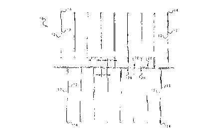
techniques. Thus, as illustrated within Figure 3, when the media storage
2 unit is extended each pocket 20 is separated from an adjacent pocket Z0
3 by a distance of "2X" inches, greatly facilitating the insertion and retrieval4 of a storage media within that pocket. tn accordance with the preferred
c; embodiment of the present invention the dimension "X" comprises 1/4
6 inch and thus, the dimension "2X" is 1/2 inch; however, those skilled in
~' the art will appreciate that a greater or lesser separation of adjacent
~I pockets may be accomplished, so long as a sufficient separation between
9 adjacent pockets is created to permit efficient insertion and retrieval of
1C) storage media within a pocket. It should also be noted that when an
11 accordion pleated media storage unit is formed in this manner, two
1,' alternate sets of storage pockets 20 may b~ formed on opposite sides of
1~, elongate flexible web 10, greatly enhancing the number of storage media
1~ elements which may be accommodated. Of course, if it is desired to
1 cj create only a single set of storage pockets on one side of elongate flexible
16 web 10, the bottom edge bond between two adjacent overlying planes
17' may be extended above the midline of each plane, so long as a gap exists
1~, between the upper point of bonding of each storage pocket thus formed
1 cl and the lower point of a top edge bond.
2CI
21 Next, referring to Figure 4, there is depicted a side view of
22 the media storage unit of Figure 3, fanned open in a first direction to
25, expose a first half of the storage pockets created therein. As illustrated,
24 when fanned open in the direction depicted within Figure 4, multiple
25 storage media elements, such as elements 22 and 24 may be inserted into
2~i various storage pockets 20 with great facility. This facility occurs as a
27 result of the novel design of the accordion pleated media storage unit
2~, which permits the upper half of each storage pocket to be fanned open,
29l while maintaining a constant dimension in the lower half of each storage
3CI pocket. Further, by providing a storage pocket in which the dimensions

CA 02228~0 l998-0l-23
WlD 97/44788 PCT/US97/11191
- 10 -
of the upper half of the pocket may vary, while maintaining as constant
2 the dimensions of the lower half of each pocket, each media storage
3 element 22 or 24 is firmly held in the center of the aperture into storage
4 pocket 20, as illustrated in Figure 4, greatly facilitating insertion and
5 retrieval of a media storage element. Those having ordinary skill in the art
6 will appreciate that each media storage element 22 and 24 may comprise
7 a compact disk, a floppy disk, or any other suitable media storage device
8 which is either circular or rectangular in shape.
As further illustrated within Figure 4, a second plurality of
11 storage pockets 20 exists within the lower half of the media storage unit
12 and as depicted, a media storage elem~ nt, such as element 26 may be
13 inserted into one of the pockets thus formed. In this manner, the density
14 within which multiple media storage elements may be stored is
1 5 substantially increased.
1 6
17 Finally, with reference to Figure 5, there is depicted a side
18 view of the media storage unit of Figure 3, fanned open in a second
19 direction to expose a second half of the storage pockets created therein.
20 As depicted within Figure 5, media storage elements 22 and 24 are now
21 substantially enclosed within a storage pocket Z0 and media storage
22 element 26 is easily accessible within its associated storage pocket 20.
23
24 As the dimensions of the upper half of the aperture into this
25 storage pocket have been expanded by the fanning of the media storage
26 unit, and as the dimensions of the lower half of storage pocket 20 have
27 been maintained, media storage element 26 is held in place in the center
28 of its storage pocket, greatly enhancing insertion and retrieval.
29

CA 02228~0 1998-01-23
~0 97/44788 PCT/US97/11191
Thus, as those having ordinary skill in this art will appreciate,
2 the media storage unit of the present invention may be utilized to
3 efficiently store a large number of storage media by a creating a plurality
4 of storage pockets, each of which is separated from an alternate storage
5 media element by a single layer of fabric.
7 Upon reference to the foregoing those skilled in the art will
8 appreciate that the Applicants herein have created an accordion pleated
9 media storage unit which includes pockets which are separable by a
10 defined distance at the upper half thereof, while maintaining a fixed
11 dimension of the lower half of each storage pocket, maintaining each
12 media storage element which has been inserted into a pocket within thc
13 center of the aperture, greatly enhancing the efficiency of insertion and
14 retrievai of a storage media element within adjacent pockets and which
15 permits a large number of storage media elements to be stored within such
16 a unit by virtue of a plurality of mirror image storage pockets created on
17 each side of the resultant media storage unit.
18
19 While the invention has been particulariy shown and
20 described with reference to a preferred embodiment, it will be understood
21 by those skilled in the art that various changes in form and detail may be
22 made therein without departing from the spirit and scope of the invention.
23

Dessin représentatif
Une figure unique qui représente un dessin illustrant l'invention.
États administratifs

2024-08-01 : Dans le cadre de la transition vers les Brevets de nouvelle génération (BNG), la base de données sur les brevets canadiens (BDBC) contient désormais un Historique d'événement plus détaillé, qui reproduit le Journal des événements de notre nouvelle solution interne.

Veuillez noter que les événements débutant par « Inactive : » se réfèrent à des événements qui ne sont plus utilisés dans notre nouvelle solution interne.

Pour une meilleure compréhension de l'état de la demande ou brevet qui figure sur cette page, la rubrique Mise en garde , et les descriptions de Brevet , Historique d'événement , Taxes périodiques et Historique des paiements devraient être consultées.

Historique d'événement

Description Date
Le délai pour l'annulation est expiré 2012-05-23
Lettre envoyée 2011-05-24
Inactive : CIB de MCD 2006-03-12
Accordé par délivrance 2003-11-04
Inactive : Page couverture publiée 2003-11-03
Inactive : Taxe finale reçue 2003-08-13
Préoctroi 2003-08-13
Un avis d'acceptation est envoyé 2003-02-24
Lettre envoyée 2003-02-24
Un avis d'acceptation est envoyé 2003-02-24
Inactive : Approuvée aux fins d'acceptation (AFA) 2003-01-29
Modification reçue - modification volontaire 2002-12-10
Inactive : Supprimer l'abandon 2002-07-25
Lettre envoyée 2002-07-25
Inactive : Demande ad hoc documentée 2002-07-25
Inactive : RE du <Date de RE> retirée 2002-07-25
Inactive : Abandon.-RE+surtaxe impayées-Corr envoyée 2002-05-23
Exigences pour une requête d'examen - jugée conforme 2002-05-21
Requête d'examen reçue 2002-05-21
Toutes les exigences pour l'examen - jugée conforme 2002-05-21
Inactive : Demandeur supprimé 1999-01-16
Déclaration du statut de petite entité jugée conforme 1999-01-05
Inactive : Correspondance - Formalités 1999-01-05
Inactive : Correspondance - Transfert 1999-01-05
Inactive : Lettre de courtoisie - Preuve 1998-11-09
Inactive : Transfert individuel 1998-09-01
Demande visant la nomination d'un agent 1998-07-16
Inactive : Correspondance - Formalités 1998-07-16
Demande visant la révocation de la nomination d'un agent 1998-07-16
Inactive : Notice - Entrée phase nat. - Pas de RE 1998-07-06
Inactive : CIB en 1re position 1998-05-12
Symbole de classement modifié 1998-05-12
Inactive : CIB attribuée 1998-05-12
Inactive : Lettre de courtoisie - Preuve 1998-05-05
Inactive : Notice - Entrée phase nat. - Pas de RE 1998-04-28
Demande reçue - PCT 1998-04-27
Demande publiée (accessible au public) 1997-11-27

Historique d'abandonnement

Il n'y a pas d'historique d'abandonnement

Taxes périodiques

Le dernier paiement a été reçu le 2003-05-09

Avis : Si le paiement en totalité n'a pas été reçu au plus tard à la date indiquée, une taxe supplémentaire peut être imposée, soit une des taxes suivantes :

  • taxe de rétablissement ;
  • taxe pour paiement en souffrance ; ou
  • taxe additionnelle pour le renversement d'une péremption réputée.

Veuillez vous référer à la page web des taxes sur les brevets de l'OPIC pour voir tous les montants actuels des taxes.

Historique des taxes

Type de taxes Anniversaire Échéance Date payée
TM (demande, 2e anniv.) - petite 02 1999-05-24 1998-01-23
Taxe nationale de base - petite 1998-01-23
Enregistrement d'un document 1998-09-01
TM (demande, 3e anniv.) - petite 03 2000-05-23 2000-05-18
TM (demande, 4e anniv.) - petite 04 2001-05-23 2001-05-15
Requête d'examen - petite 2002-05-21
TM (demande, 5e anniv.) - petite 05 2002-05-23 2002-05-23
TM (demande, 6e anniv.) - petite 06 2003-05-23 2003-05-09
Taxe finale - petite 2003-08-13
TM (brevet, 7e anniv.) - petite 2004-05-25 2004-05-17
TM (brevet, 8e anniv.) - petite 2005-05-23 2005-04-25
TM (brevet, 9e anniv.) - petite 2006-05-23 2006-04-24
TM (brevet, 10e anniv.) - petite 2007-05-23 2007-05-10
TM (brevet, 11e anniv.) - petite 2008-05-23 2008-05-21
TM (brevet, 12e anniv.) - petite 2009-05-25 2009-05-19
TM (brevet, 13e anniv.) - petite 2010-05-25 2010-05-17
Titulaires au dossier

Les titulaires actuels et antérieures au dossier sont affichés en ordre alphabétique.

Titulaires actuels au dossier
CD3 STORAGE SYSTEMS, INC.
Titulaires antérieures au dossier
RONALD E. HUNT
VERLON E. WHITEHEAD
Les propriétaires antérieurs qui ne figurent pas dans la liste des « Propriétaires au dossier » apparaîtront dans d'autres documents au dossier.
Documents

Pour visionner les fichiers sélectionnés, entrer le code reCAPTCHA :


Pour visualiser une image, cliquer sur un lien dans la colonne description du document. Pour télécharger l'image (les images), cliquer l'une ou plusieurs cases à cocher dans la première colonne et ensuite cliquer sur le bouton "Télécharger sélection en format PDF (archive Zip)" ou le bouton "Télécharger sélection (en un fichier PDF fusionné)".

Liste des documents de brevet publiés et non publiés sur la BDBC .

Si vous avez des difficultés à accéder au contenu, veuillez communiquer avec le Centre de services à la clientèle au 1-866-997-1936, ou envoyer un courriel au Centre de service à la clientèle de l'OPIC.


Description du
Document 
Date
(aaaa-mm-jj) 
Nombre de pages   Taille de l'image (Ko) 
Dessin représentatif 1998-05-21 1 9
Page couverture 2003-09-30 1 45
Page couverture 1998-05-21 1 53
Abrégé 1998-01-23 1 56
Revendications 1998-01-23 7 180
Dessins 1998-01-23 5 120
Description 1998-01-23 11 368
Avis d'entree dans la phase nationale 1998-04-28 1 193
Avis d'entree dans la phase nationale 1998-07-06 1 209
Demande de preuve ou de transfert manquant 1999-01-26 1 110
Courtoisie - Certificat d'enregistrement (document(s) connexe(s)) 1999-02-25 1 117
Rappel - requête d'examen 2002-01-24 1 117
Accusé de réception de la requête d'examen 2002-07-25 1 193
Avis du commissaire - Demande jugée acceptable 2003-02-24 1 160
Avis concernant la taxe de maintien 2011-07-05 1 171
PCT 1998-01-23 4 120
Correspondance 1998-05-05 1 29
PCT 1998-03-10 1 30
Correspondance 1998-07-16 2 59
PCT 1998-03-06 3 103
PCT 1998-08-21 1 47
Correspondance 1998-11-06 1 13
Correspondance 1999-01-05 3 104
Correspondance 2003-08-13 1 33
Taxes 2002-05-23 1 25
Taxes 2001-05-15 1 36
Taxes 2004-05-17 1 39
Taxes 2009-05-19 1 41
Taxes 2010-05-17 1 29