Note : Les descriptions sont présentées dans la langue officielle dans laquelle elles ont été soumises.
CA 02229276 1998-02-11
WO 97/08504 PCTISE96/00919
1
METHOD FOR DRYING WOOD
The present invention relates to a method of drying wood in
accordance with the preamble of Claim 1.
Wood is dried industrially in so-called chamber dryers, by
circulating air of given temperature and humidity around
cross-laid layers of wood through openings defined between
mutually superposed wood packs. The circulation air functions
as a heat transferring and moisture transporting medium,
wherein the heat required to dry the wood is supplied to the
air through the medium of heating batteries, while the air
is dehumidified by ventilation, for instance by diluting with
cold, dry outdoor air.
Chamber-drying processes are at present controlled in many
different ways. The principle on which drying climates are
controlled is normally based on an established control
schedule which allows air temperature and air humidity to
vary in a predetermined manner throughout the whole of the
drying process. It is known from experience, for instance,
that the rate at which wood is dried must be constrained
during the first stage of the drying process, otherwise the
wood will split. Similarly, the chamber temperature is often
increased during the latter part of the drying process, in
order to maintain the slow migration of moisture in the wood
when the water is in a bound state.
There are at present many different types of drying sched-
ules, which are either proposed by the supplier of the wood
dryer or which have been tested locally in individual
sawmills and wood yards. However, controlling of the drying
, process has a serious principle deficiency, since the state
of the circulation air is not controlled in a feedback
manner, i.e. the process control does not take into account
the prevailing moisture-emitting properties and the initial
CA 02229276 1998-02-11
WO 97/08504 PCT/SE96/00919
2
moisture quotient of the wood. This can result in serious
errors of judgement on the part of the operator responsible
for the drying operation with regard to choice of drying =
schedule, with subsequent damage to the wood or time losses
as a direct result. Judgement errors will also result in
energy losses, of course. Excessive drying of the wood will
also result in splitting and excessive shrinkage of the wood.
The object of the present invention is to provide a highly
attractive and advantageous method of drying wood. This
object is achieved with a wood drying method that has the
characteristic features set forth in the following Claims.
The following advantages are among the many advantages that
are afforded by the invention: Because the drying process is
controlled as a feedback system, the drying process can be
adapted very effectively to the true drying requirements of
the batch of wood concerned, therewith resulting in optimal
drying of the wood. The invention also enables the establish-
ment of a reliable time-point at which a desired final
moisture quotient (average moisture quotient) is achieved,
therewith enabling the drying process to be automatically
interrupted and switched to an optional conditioning phase.
This will avoid, for instance, excessive drying of the wood
with subsequent splitting and excessive shrinkage of the
wood. The inventive drying method is also highly energy-
saving. The invention thus affords both technical and
economical advantages.
The invention will now be described in more detail with
reference to exemplifying embodiments thereof and also with =
reference to the accompanying drawings, in which Fig. 1 is
a vertical sectional view of a drying chamber; Fig. 2 is a
horizontal sectional view of the drying chamber shown in Fig.
1; and Fig. 3 is a time-temperature diagram illustrating the
inventive wood-drying method.
CA 02229276 1998-02-11
WO 97/08504 PCT/SE96/00919
3
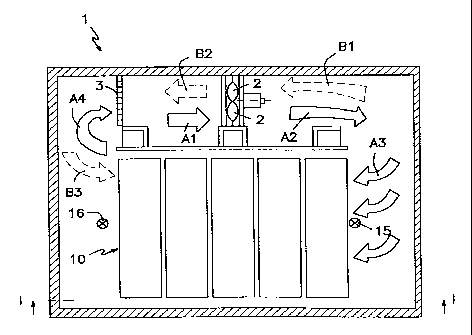
Figs. 1 and 2 illustrate an example of a wood-dryer 1 with
which the inventive method can be applied. The illustrated
drying chamber 1 has a construction typical in the field and
includes fans 2 and heating batteries 3. In addition, the
chamber naturally also includes a floor, walls, ceiling and
baffles for guiding circulating drying air through a batch
of wood 10 to be dried in a desired manner. The batch of wood
will normally comprise a plurality of cross-laid wood
packs, designated 10a, 10b, 10c, and so on, in Figs. 1 and
10 2. it will be understood, however, that the drying chamber
1 can be constructed differently to that illustrated in Figs.
1 and 2. For instance, fans 2 and heating batteries 3 may be
ceiling-mounted instead of being mounted on the sides of the
chamber as in the illustrated case. It will also be under-
stood that the inventive drying process is not restricted to
a given type of drying chamber, and that the process can be
applied to all conceivable types of drying chamber.
The drying chamber illustrated in Figs. 1 and 2 enables the
direction of air flow to be changed during the drying
process, for instance by reversible operation of the fans 2.
The direction of air flow is shown in Fig. 2 by full arrows
A1-A4, while the opposite direction of air flow is indicated
by broken-line arrows Bl-B3. As indicated by the arrows Cl
and Dl, the ingress of outdoor air or ambient air is con-
trolled by means of a throttle or valve, while exhaust air
leaving the chamber is controlled by a throttle or valve as
indicated by the arrow El.
The inventive method is made possible by virtue of a sensor,
for instance in the form of a psychrometer, mounted in the
drying chamber. In this regard, a first psychrometer 15 is
conveniently mounted adjacent the wood batch 10 on one side
thereof, while a second psychrometer 16 is conveniently
mounted on the opposite side of the wood batch 10, such that
one psychrometer will be impinged upon by the circulation air
as it enters a wood batch to be dried, and such that the
CA 02229276 1998-02-11
WO 97/08504 PCT/SE96/00919
4
other psychrometer will be impinged upon by the circulation
air as it exits from said wood batch. Naturally, this applies
irrespective of the prevailing direction of air circulation.
In order to enable wood batches 10 to be placed in and
removed from the drying chamber 1, it is necessary for the
first psychrometer 15 to be mobile so that it can be moved
to an inactive position in which wood packs can be moved into
and out of the chamber, while enabling the psychrometer to
be moved back to its active position prior to starting the
drying process, as indicated in Figs. 1 and 2. Both psychro-
meters 15 and 16 are able to measure both normal temperature
(dry temperature) and wet temperature of the air circulating
in the drying chamber. It will be understood that the
psychrometers can be replaced with alternative measuring
devices having the aforesaid temperature measuring qualifica-
tions. It is also possible to use only one single psychrome-
ter or only one single measuring device when the direction
of air circulation is reversed sufficiently often.
Naturally the drying chamber 1 will also be provided with the
control apparatus and guide means necessary to carry out the
inventive method.
The inventive wood-drying method will now be described in
more detail.
This description is started from the stage in which the
drying chamber 1 has been loaded with a wood batch 10 to be
dried and in which the psychrometers 15 and 16 have been
placed in suitable positions in the proximity of the inflow
of circulation air to the wood batch and to the outflow of
circulation air leaving said batch.
A first stage in the drying process involves a so-called
heating phase (phase I). The purpose of this phase is to heat
the wood without drying the same, wherein the wood will
normally be sprayed with water and/or steam.
CA 02229276 1998-02-11
WO 97/08504 PCT/SE96/00919
The duration of the heating phase will, of course, depend on
the size of_the wood batch 10 and its initial temperature TO,
which often corresponds to the prevailing outdoor tempera-
ture, among other things.
The heating phase may be continued until the wood has been
heated sufficiently to meet subsequent drying activities. The
heating phase (phase I) is illustrated in Fig. 3, wherein the
upper curve (line) exemplifies the increase in dry tempera-
ture and the lower curve exemplifies the increase in wet
temperature during the heating phase.
When a desired preheating level has been reached, phase I is
accordingly terminated and phase II is initiated, this phase
being referred to as the initiating phase.
The initiating phase (phase II) is effected in accordance
with dry temperature (T1) control values (e.g. 55 C) and
wet-temperature (TV1) control value (e.g. 50 C) that have
been preset by the dryer operator. The choice of said
temperature values is based on experience and, for instance,
on the wishes of the customer with regard to the appearance
of the wood. The choice of temperature is not a completely
free choice, and upper and lower temperature limits are
included in order to prevent damage to the wood-in this stage
of the process. Phase II, the initiating phase, is normally
continued for from 3-6 hours.
The wood batch 10 begins to dry in the initiation phase, i.e.
water vapour is given off to the circulation air, which
therewith loses thermal energy and exhibits a continuously
measurable drop in dry temperature as the air is blown
through the batch. This dry temperature drop, OT, constitutes
the temperature difference between dry temperatures measured
by respective measuring devices 15 and 16 and may be in the
region of 3 C, for instance. By forming a mean time value,
this temperature drop AT can be read-off upon termination of
CA 02229276 1998-02-11
WO 97/08504 PC'T/SE96/00919
6
the initiation phase (phase II), and the following phases
controlled so that the temperature drop AT will be essential-
ly equal to the mean value of the temperature drop obtained =
in the initiation phase (phase II). This operational control
will result in an essentially constant drying rate in
practice.
The wet temperature TV1 is maintained at a desired level, by
removing heat, humid air and, for instance, supplying cold,
dry outdoor air, for instance, with the aid of control
valves, and by supplying heat at the same time so as to keep
the dry temperature Ti at a desired level. The purpose of
phase II is to obtain a response from the wood batch 10
concerned with regard to its moisture status. A large dry
temperature drop OT across the wood batch 10 indicates that
the wood has a high moisture content. A small dry temperature
drop OT indicates the opposite. The object is to glean
knowledge which can be utilized in subsequent phases so as
to maintain the dry temperature drop OT (e.g. 3 C) essential-
ly constant.
After continuing the initiation phase (phase II) for a chosen
length of time (e.g. 3-6 hours), the process is switched to
the next phase, which can be referred to as the temperature
increasing phase (phase III).
The dry temperature T1 can be defined as the mean value of
the dry temperatures recorded by the psychrometers 15 and 16,
and similarly the wet temperature TV1 may be comprised of the
mean value of the wet temperatures recorded by the psychro-
meters 15 and 16. It will be understood, however, that the
process can be based solely on the dry-temperature and wet-
temperature recording on one of said two psychrometers,
without departing from the inventive concept.
CA 02229276 1998-02-11
WO 97/08504 PCT/SE96/00919
7
This discussion regarding temperature.definition also applies
in the following to dry and wet temperatures during remaining
phases.
In the temperature increasing phase (phase III), the wood
drying process is controlled in a manner to keep the wet
temperature TV1 (e.g. 50 C) constant, whereas the dry
temperature T is increased immediately the dry-temperature
drop AT e.g. 3 C between the sensors 15 and 16 tends to fall.
This results in faster migration of moisture in the wood and
it is possible to hold up evaporation in the wood surfaces
to the same level as was earlier the case. This is allowed
to continue until a preset upper limit temperature T2 (e.g.
65 C) is reached. This dry temperature limit T2 is set within
reasonable limits by a process responsible operator. The
maximum temperature T2 is determined partly by wood appear-
ance aspects and also by the heat sensitivity of mechanical
equipment and electrical installations.
It shall thus be ensured that phase III takes place with the
wet temperature TV (e.g. 50 C) held constant and with an
essentially constant temperature drop AT (e.g. 3 C), where-
with the dry temperature T is allowed to increase from its
value according to phase II (e.g. 55 C) to a maximum value T2
(e.g. 65 C) so as to essentially maintain the dry temperature
drop AT (e.g. 3 C) between the sensors 15 and 16. Effective
moisture migration from the wood batch 10 is maintained in
this way during the whole of phase III, which may have a
duration of two calendar days, for instance. Phase III has
been completed when the limited T2-value (e.g. 65 C) has been
reached.
When the temperature increasing phase (phase III) is termi-
nated phase IV is commenced, this phase being referred to as
the wet-temperature lowering phase.
CA 02229276 1998-02-11
WO 97/08504 PCT/SE96/00919
8
The wet-temperature lowering phase (phase IV) is continued
in a manner such as to maintain the dry temperature T2 (e.g.
65 C) reached in phase III constantly at its limited maximum
level, while lowering the wet temperature TV at the same time
such that the dry temperature drop AT will still be essen-
tially constant (e.g. 3 C). Thus, an essentially constant
dry-temperature drop LT (e.g. 3 C) is also strived for in
this phase, and is enabled by controlling operation of the
dry chamber in a manner to lower the wet temperature from TVl
(e.g. 50 C) to a limited minimum value TV2 (e.g. 45 C). TV2
is limited downwards to avoid excessively pronounced surface-
drying of the wood.
Evaporation of moisture from the wood can be kept at a
constant level in the wet-temperature lowering phase (phase
IV), by circulating drier air, i.e. by allowing the wet
temperature TV to fall at the rate necessary to maintain a
constant dry temperature drop AT. This drying phase involves
allowing the moisture quotient of the wood surfaces to fall
to a level set by the dryer operator in the form of said
bottom limit temperature TV2 for the wet temperature. The
wet-temperature lowering phase (phase IV) is often of
relatively short duration in relation to the temperature
increasing phase (phase III) and phase IV is thus terminated
2S when the wet temperature TV2 reaches the -bottom limit
temperature (e.g. 45 C) .
When the wet-temperature lowering phase (phase IV) is
terminated, the process controller will leave the stage of
the wood-drying process in which the process is controlled
on the basis of the dry temperature drop LT, i.e. where a
constant or essentially constant temperature drop AT consti-
tutes a control value and control parameter. The process
control now passes to a final phase, which can be referred
to as a constant holding phase or a plateau phase (phase V).
CA 02229276 1998-02-11
WO 97/08504 PCT/SE96/00919
9
The constant holding phase/plateau phase (phase V) can be
said to constitute a final phase of the actual drying part
of the process and in the present case is intended to dry the
wood batch to a predetermined mean moisture quotient. This
is achieved by controlling the process in a manner to
maintain the dry upper limit temperature T2 and the wet lower
limit temperature TV2 constantly at the preset control
values. In this regard, the drying process can be described
generally as a diffusion controlled process at given border
conditions, meaning that the moisture flow decreases together
with the dry temperature drop AT.
The dry temperature T2 (e.g. 65 C) and the wet temperature
TV2 (e.g. 45 C) are thus both constant during this phase. The
dry temperature drop AT (initially 3 C, for instance)
decreases successively during this phase when, e.g., the flow
of circulation air is kept constant in relation to earlier
phases. The aforesaid reduction in dry temperature drop AT
causes the departure of moisture from the wood batch 10 to
decrease successively. The mean moisture quotient of the wood
batch 10 can be calculated on the basis of the dry tempera-
ture drop AT that prevails at each point in time and on the
basis of the wood dimensions concerned, wherein the constant
holding phase (phase V) is interrupted when the desired mean
moisture quotient (e.g. 15%-) has been reached, said phase
having a duration of one calendar day, for instance.
Calculation of the mean moisture quotient is based on the
following facts. By assuming that the moisture flow is
diffusion controlled in the wood during phase V and that the
border conditions are given by virtue of knowing the state
and flow of the circulation air, there can be formulated an
arithmetical algorithm by means of which the mean moisture
quotient of the wood can be calculated. This enables the dry
temperature drop AT to be read-off continuously in the
control process, and a calculation to be made which continu-
ously discloses the expected mean moisture quotient in the
CA 02229276 1998-02-11
WO 97/08504 PCT/SE96/00919
wood batch. When the calculated mean moisture quotient
coincides with the given final moisture quotient, the drying
process is interrupted and a switch is made to an optional
conditioning phase.
5 ~
Thus, when the constant holding phase (phase V) is terminat-
ed, the wood batch 10 may be subsequently treated in a
conventional manner, for instance by conditioning and cooling
the wood prior to its removal from the drying chamber 1.
The aforedescribed process control principles form the basic
framework of the inventive feedback process control. This
also includes a method of controlling the flow of circulation
air, for instance with the aid of a frequency converter
connected to the drive motors of the circulation fans.
In order to save energy, the flow of circulation air can be
reduced during phase V, for instance in accordance with the
following principles.
It is known that the air-flows in the final phase of the
drying process need not be equally as large as at the
beginning of the process. This is because the departure of
moisture from the wood is controlled by different mechanisms
in the initial and final drying phases respectively. Thus,
expensive electric energy can be saved by reducing the flow
and the rate of flow of the circulation air with no negative
affect on the drying quality. This can also be affected in
a feedback mode in accordance with the following model.
When the wood enters the constant holding phase (phase V),
drying of the wood is relatively independent of the air flow
rate/air flow, and depends mainly on the temperature of the
wood and the diffusion rate associated therewith. It is thus
possible to reduce the flow of circulation air without
retarding the drying process, by using one of the following
three alternatives, for instance:
CA 02229276 1998-02-11
WO 97/08504 PCT/SE96/00919
11
1. Reducing the air flow to a constant and lower level.
2. Reducing the air flow in accordance with a time-con-
trolled ramp function.
3. Reducing the air flow towards a constant dry temperature
drop AT.
This last possibility deserves an additional comment. Thus,
the circulation air flow/flow rate can also be controlled in
the constant holding phase (phase V) so as to obtain a
constant dry temperature drop AT. In principle, this means
that instead of the dry temperature drop OT decreasing at a
constant rate of air flow the opposite takes place, namely
the rate of air flow or the flow of circulation air decreases
so as to maintain the temperature drop AT constant.
Thus, this principle provides a very simple feedback control
with regard to only one process parameter, the dry tempera-
ture drop AT, which also remains constant throughout the
entire process. Naturally, the magnitude of the circulation
air flow must also be taken into account when calculating the
mean moisture quotient of the wood batch.
The aforedescribed control principle can be supplemented with
an interface against the dryer operator, i.e. a supportive
sub-program for strategic selection of process parameters.
The control principle also provides the operator with wide
control facilities over the process, despite the process
being feedback self-regulating, among other things by the
choice of border temperature levels. This also affords a
pedagogical advantage, because the basic control principles
can be easily related to the behaviour of wood in a dryer
environment with regard to splitting tendencies, colour
changes, resin migration, etc.
Neither is there anything to prevent different heating or
conditioning methods being chosen, irrespective of whether
CA 02229276 1998-02-11
WO 97/08504 PCT/SE96/00919
12
they are applied in water-based systems or steam-based
systems or combinations thereof.
It will be understood that such parameters as drying chamber
acclimatization, air flows, etc., are controlled in a manner
which will enable the inventive drying method to be carried
out in accordance with established principles. Reversal of
the flow of circulation air will suitably take place at
regular time intervals. A maximum flow of circulation air is
normally used during phases I to IV, whereas the circulation
air flow in phase V may be chosen in accordance with differ-
ent principles as indicated above.
It should be noted that phase II must always be run, in order
to obtain information necessary for the following phases.
Either phase III or phase IV must also be run. It is neces-
sary to run phase IV, so that the final moisture quotient can
be calculated.
When necessary, the drying process can be carried out with
the use of only one psychrometer, provided that the air flow
in the drying chamber is reversed often enough. Naturally,
measuring devices other than psychrometers may be used,
providing that these devices will provide the necessary
temperature information. -
It will also be understood that other drying media than air
can be used when such use is found appropriate.
It will also be understood that the aforesaid temperature
examples are not limiting in any way, and that temperature
control values and temperature limits can be chosen in
accordance with prevailing conditions and circumstances. It
will also be seen that a constant temperature implies in
practice a substantially constant temperature, since control
equipment and regulating equipment will naturally have
limitations, among others.
CA 02229276 1998-02-11
WO 97/08504 PCT/SE96/00919
13
Also worthy of mention is the possibility of controlling and
regulating the dry temperature drop AT in a manner to follow
a predetermined variation pattern, as an alternative to the
earlier mentioned essentially constant dry temperature drop
AT, wherein if desirable said variation pattern will deviate
from the aforesaid constant maintained temperature drop
during one or more of the relevant phases II-IV and possibly
phase V.
In the feedback control system described above, the dry
temperature change AT of the circulation air obtained when
blowing air through the wood batch 10 is the central feedback
parameter. The greater the temperature drop AT, the greater
the departure of moisture from the wood. It is possible to
calculate from the thermodynamics of the air the relationship
between the dry temperature drop AT and the departure of
moisture when certain base parameters are known, for instance
the circulation air flow and the amount of wood involved. In
other words, the requisite information can be readily
obtained by placing, e.g., psychrometers on a respective side
of the wood batch. In this regard, it is important that the
dry thermometers are positioned so that a representative
value of the temperature drop of the circulation air can be
obtained without interference from leakage air and the like.
Naturally, positioning of the measuring devices and the
number of such devices, for instance psychrometers, may be
varied in accordance with prevailing conditions, so as to
enable sufficiently reliable measurement values to be
obtained for controlling the wood-drying process.
The invention is thus not restricted to the illustrated and
described embodiments thereof, since changes and modifica-
tions can be made within the scope of the following Claims.