Sélection de la langue

Search

Sommaire du brevet 2230204 

Énoncé de désistement de responsabilité concernant l'information provenant de tiers

Une partie des informations de ce site Web a été fournie par des sources externes. Le gouvernement du Canada n'assume aucune responsabilité concernant la précision, l'actualité ou la fiabilité des informations fournies par les sources externes. Les utilisateurs qui désirent employer cette information devraient consulter directement la source des informations. Le contenu fourni par les sources externes n'est pas assujetti aux exigences sur les langues officielles, la protection des renseignements personnels et l'accessibilité.

Disponibilité de l'Abrégé et des Revendications

L'apparition de différences dans le texte et l'image des Revendications et de l'Abrégé dépend du moment auquel le document est publié. Les textes des Revendications et de l'Abrégé sont affichés :

  • lorsque la demande peut être examinée par le public;
  • lorsque le brevet est émis (délivrance).
(12) Demande de brevet: (11) CA 2230204
(54) Titre français: DISPOSITIF DE DISTRIBUTION DE LIQUIDES
(54) Titre anglais: LIQUID DISPENSING DEVICE
Statut: Réputée abandonnée et au-delà du délai pour le rétablissement - en attente de la réponse à l’avis de communication rejetée
Données bibliographiques
(51) Classification internationale des brevets (CIB):
  • B67C 03/28 (2006.01)
  • B65B 39/00 (2006.01)
  • B67C 03/26 (2006.01)
(72) Inventeurs :
  • CORNIANI, CARLO (Italie)
  • VESENTINI, RENZO (Italie)
(73) Titulaires :
  • AZIONARIA COSTRUZIONI MACCHINE AUTOMATICHE A.C.M.A. S.P.A.
  • AZIONARIA COSTRUZIONI MACCHINE AUTOMATICHE A.C.M.A. S.P.A.
(71) Demandeurs :
  • AZIONARIA COSTRUZIONI MACCHINE AUTOMATICHE A.C.M.A. S.P.A. (Italie)
  • AZIONARIA COSTRUZIONI MACCHINE AUTOMATICHE A.C.M.A. S.P.A. (Italie)
(74) Agent: SMART & BIGGAR LP
(74) Co-agent:
(45) Délivré:
(22) Date de dépôt: 1998-02-23
(41) Mise à la disponibilité du public: 1998-08-25
Licence disponible: S.O.
Cédé au domaine public: S.O.
(25) Langue des documents déposés: Anglais

Traité de coopération en matière de brevets (PCT): Non

(30) Données de priorité de la demande:
Numéro de la demande Pays / territoire Date
BO97A 000090 (Italie) 1997-02-25

Abrégés

Abrégé français

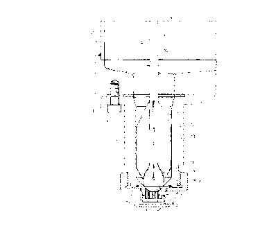
Divulgation d'un dispositif pour distribuer des liquides. Un élément de distribution à l'extérieur, situé à l'extrémité d'un conduit d'alimentation, présente une partie supérieure d'entrée communiquant avec le conduit et engagé de manière étanche par un élément vanne se déplaçant dans l'axe à l'intérieur du conduit, ainsi qu'une partie inférieure de sortie percée d'un certain nombre d'orifices communiquant avec le conduit; chaque orifice est défini au fond par une surface plate horizontale et compte un élément tubulaire respectif engagé à l'intérieur de l'orifice lui-même et ayant une extrémité se prolongeant de la surface plate et transversalement par rapport à elle.


Abrégé anglais


A device for dispensing liquids, wherein an output
distributing element, located at the end of a supply
conduit, has an upper input portion communicating with
the conduit and engaged in fluidtight manner by a valve
element movable axially inside the conduit, and a lower
output portion having a number of holes communicating
with the conduit; each hole is defined at the bottom by
a horizontal flat surface, and has a respective tubular
element fitted inside the hole itself and having an end
portion projecting from and crosswise to the flat
surface.

Revendications

Note : Les revendications sont présentées dans la langue officielle dans laquelle elles ont été soumises.


-8-
THE EMBODIMENTS OF THE INVENTION IN WHICH AN EXCLUSIVE
PROPERTY OR PRIVILEGE IS CLAIMED ARE DEFINED AS FOLLOWS:
1) A dispensing device for liquids, comprising a
supply conduit; an output distributing element for the
liquid, fitted to the bottom of the conduit and engaged
by a bottle for filling; and a valve element movable
with respect to the conduit to engage the distributing
element and regulate supply of the liquid from the
conduit; the distributing element comprising an upper
input portion defining an end portion of the conduit,
and a lower output portion having at least one through
hole communicating with said conduit and defined at the
bottom by a flat surface crosswise to the hole itself;
and the dispensing device being characterized in that
said distributing element comprises a tubular element
fitted inside said hole and having an end portion
projecting from and crosswise to said flat surface.
2) A device as claimed in Claim 1, characterized
in that the lower output portion comprises a number of
holes; and a tubular element fitted inside each hole and
having a respective end portion projecting from and
crosswise to said flat surface.
3) A device as claimed in Claim 2, characterized
in that said holes are arranged on said flat surface in
at least two concentric rows.
4) A device as claimed in Claim 2, characterized
in that said tubular elements are fitted removably

-9-
inside the respective holes.
5) A device as claimed in Claim 1, characterized
in that said distributing element also comprises an
annular jacket surrounding said lower output portion and
said tubular elements, and extending beyond the end
portions of the tubular elements.
6) A device as claimed in Claim 5, characterized
in that said jacket comprises a number of horizontal
orifices formed through the jacket substantially at said
flat surface.
7) A device as claimed in Claim 1, characterized
in that said valve element comprises a stem movable back
and forth inside said supply conduit; and guide means
for keeping the stem substantially parallel to the
conduit; the stem comprising a substantially spherical
bottom head for engaging said distributing element in
fluidtight manner.
8) A device as claimed in Claim 7, characterized
in that said upper input portion of said distributing
element comprises a hemispherical seat defining said
holes at the top, and which is engaged in fluidtight
manner by said head.
9) A device as claimed in Claim 8, characterized
in that said seat comprises a bottom surface of
substantially the same shape as said head so as to
receive in fluidtight manner at least a bottom end
portion of said head.

Description

Note : Les descriptions sont présentées dans la langue officielle dans laquelle elles ont été soumises.


' CA 02230204 1998-02-23
., -- 1 --
LIQUID DISPENSING DEVICE
The present invention relates to a liquid
dispensing device.
More specifically, the present invention relates
to a liquid dispensing device of the type comprising a
supply conduit; a liquid output distributing element
fitted to the bottom end of the conduit and which is
engaged by a bottle for filling; and a valve element
movable with respect to the supply conduit to engage the
distributing element in fluidtight manner and regulate
supply of the liquid.
Known dispensing devices of the above type are
normally fed along a circular path by a carousel
conveyor rotating about a vertical axis, and are engaged
cyclically by the bottles for filling. More
specifically, each distributing element comprises an
input portion having a substantially conical inner
surface, defining an end portion of the conduit, and
engaged in fluidtight manner by the valve element; and a
tubular output portion, which is defined externally by a
substantially cylindrical outer surface so sized as to
be partly insertable inside a bottle, and comprises one

CA 02230204 1998-02-23
- 2 -
or more vertical through holes defined at the top by the
substantially conical inner surface, and at the bottom
by a flat horizontal surface crosswise to the
substantially cylindrical outer surface.
Dispensing devices of the above type involve
several drawbacks, due to the fact that, once a given
amount of liquid is dispensed inside the bottle and the
valve element is set to close the input portion of the
distributing element, the liquid left inside the
vertical holes has neither sufficient force nor speed to
be fed into the bottle before this is detached from the
output portion of the valve element. As a result, the
remaining liquid drips from the holes and, given the
substantial continuity of the bottom edges of the holes
and said flat surface, also spreads over the flat
surface to form a film of liquid which, as the conveyor
is rotated, is hurled outwards of the conveyor.
It is an object of the present invention to
provide a liquid dispensing device designed to overcome
the aforementioned drawbacks.
According to the present invention, there is
provided a dispensing device for liquids, comprising a
supply conduit; an output distributing element for the
liquid, fitted to the bottom of the conduit and engaged
by a bottle for filling; and a valve element movable
with respect to the conduit to engage the distributing
element and regulate supply of the liquid from the
conduit; the distributing element comprising an upper

CA 02230204 1998-02-23
input portion defining an end portion of the conduit,
and a lower output portion having at least one through
hole communicating with said conduit and defined at the
bottom by a flat surface crosswise to the hole itself;
and the dispensing device being characterized in that
said distributing element comprises a tubular element
fitted inside said hole and having an end portion
projecting from and crosswise to said flat surface.
A non-limiting embodiment of the present invention
will be described by way of example with reference to
the accompanying drawings, in which:
Figure 1 shows a side view, with parts in section
and parts removed for clarity, of a preferred embodiment
of the dispensing device according to the present
invention;
Figure 2 shows a larger-scale top plan view of a
detail in Figure 1;
Figure 3 shows a section along line III-III in
Figure 2.
Number 1 in Figure 1 indicates a liquid dispensing
device fittable to the periphery of a known carousel
bottling conveyor (indicated as a whole by 2) rotating
substantially continuously about a vertical axis (not
shown) to feed device 1 along a given circular path
extending in series through a loading station (not
shown) where device 1 is engaged by an empty bottle 3,
and an unloading station where device 1 is detached from
the by then full bottle 3.

CA 02230204 1998-02-23
-- 4
Device 1 extends vertically downwards from a
bottom surface 4 of conveyor 2, and comprises a tubular,
substantially cylindrical element S having an axis A
parallel to the rotation axis of conveyor 2, and in turn
comprising a through inner supply conduit 6 coaxial with
axis A; and an output distributing element 7 for the
liquid, fitted to the bottom of tubular element 5 and
maintained coaxial with axis A and in fluidtight contact
with element 5 by a ring nut 8 screwed to one end of
element 5.
Device 1 also comprises a valve element 9, which
is fitted in sliding manner inside conduit 6, is moved
axially back and forth, by a known actuating device (not
shown), with respect to conduit 6 to engage distributing
element 7 in fluidtight manner and regulate supply of
the liquid, and in turn comprises a stem 10 with a
substantially spherical bottom head 11, and guide means
defined by a number of guide fins 12 extending radially
from stem 10 and contacting an inner surface 13 of
conduit 6 to guide stem 10 axially and keep it
equidistant from surface 13. More specifically, head 11
comprises a bowl-shaped bottom cap 14 defining the
bottom end of head 11, and which may be separate from
head 11 and made of rubber, teflon or steel.
As shown in Figures 2 and 3, distributing element
7 comprises an upper input portion 15 defining an end
portion of supply conduit 6; and a lower output portion
16, which is positioned facing the inlet 26 of an empty

CA 02230204 1998-02-23
bottle 3, and has a number of through liquid outlet
holes 17 communicating with conduit 6. More
specifically, on the side facing conduit 6, upper input
portion lS comprises a hemispherical seat 18, the bottom
surface 19 of which is of the same shape as, and is
engaged in fluidtight manner by, cap 14 of stem 10; and
lower portion 16 is defined at the bottom by a flat
surface 20 crosswise to axis A, and holes 17 extend
between seat 18 and surface 20, and are arranged
parallel to one other in two concentric rows 21, 22.
Distributing element 7 also comprises, for each
hole 17, a respective tubular diffusing element 23,
which is fitted inside hole 17 and comprises a
respective end portion 24 projecting crosswise from
surface 20. More specifically, tubular elements 23 are
fitted removably inside respective holes 17, and have an
inside diameter depending on the type of liquid being
dispensed and, like a pipet, such as to prevent the
liquid from dripping once head 11 engages seat 18 with
cap 14 contacting bottom surface 19. The end portions 24
of tubular elements 23 comprise beveled bottom outer
edges 25, and project from surface 20 by a given length
L such as to interrupt surface 20 and prevent the
formation of a film of liquid on surface 20.
Distributing element 7 is positioned facing inlet 26 of
bottle 3 so that axis A coincides with the axis of
bottle 3.
Distributing element 7 also comprises an annular

CA 02230204 1998-02-23
jacket 27 integral with lower output portion 16,
extending from surface 20 and about tubular elements
23, and of an axial len.gth L1 greater than length L of
elements 23, so as to extend axially beyond the
projecting end portions 24 of elements 23. Jacket 27
defines, together with surface 20, an open-bottomed
cylindrical cavity 28, and comprises a number of
horizontal radial orifices 29 formed through jacket 27
substantially at surface 20 and for connecting cavity 28
to the outside atmosphere. More specifically, as the
liquid is dispensed through tubular elements 23,
orifices 29 prevent the formation inside cavity 28 of a
vacuum capable of expanding the jet of liquid from
elements 23 and producing turbulence preventing bottle 3
from being filled.
In actual use, conveyor 2 rotates continuously
about said rotation axis to feed dispensing device 1
through said loading station, where device 1 receives a
respective bottle 3 positioned with inlet 26 beneath
elements 23 and coaxial with element 7.
Once inlet 26 is so positioned, said actuating
device raises stem 10 along conduit 6 to detach head 11
from seat 18 and permit the liquid the flow into bottle
3 through tubular elements 23. Bottle 3 is filled at it
travels along said circular path, and the liquid supply
is cut off as head 11 once more engages seat 18 upstream
from the unloading stati.on, where the by now full bottle
3 is detached in known manner from device 1, which is

CA 02230204 1998-02-23
fed back to the loading station.
Once head 11 engages seat 18 and bottle 3 is
detached from device 1, the liquid remaining inside
tubular elements 23 is retained inside elements 23
themselves, which, given their inside diameters,
function in the same way as a pipet, which, once filled
and closed at the top, may be positioned vertically
without the liquid inside issuing from the open bottom
end.

Dessin représentatif
Une figure unique qui représente un dessin illustrant l'invention.
États administratifs

2024-08-01 : Dans le cadre de la transition vers les Brevets de nouvelle génération (BNG), la base de données sur les brevets canadiens (BDBC) contient désormais un Historique d'événement plus détaillé, qui reproduit le Journal des événements de notre nouvelle solution interne.

Veuillez noter que les événements débutant par « Inactive : » se réfèrent à des événements qui ne sont plus utilisés dans notre nouvelle solution interne.

Pour une meilleure compréhension de l'état de la demande ou brevet qui figure sur cette page, la rubrique Mise en garde , et les descriptions de Brevet , Historique d'événement , Taxes périodiques et Historique des paiements devraient être consultées.

Historique d'événement

Description Date
Inactive : CIB de MCD 2006-03-12
Demande non rétablie avant l'échéance 2001-02-23
Le délai pour l'annulation est expiré 2001-02-23
Réputée abandonnée - omission de répondre à un avis sur les taxes pour le maintien en état 2000-02-23
Modification reçue - modification volontaire 1998-09-08
Inactive : Transfert individuel 1998-09-08
Demande publiée (accessible au public) 1998-08-25
Inactive : CIB attribuée 1998-06-03
Symbole de classement modifié 1998-06-03
Inactive : CIB en 1re position 1998-06-03
Inactive : Lettre de courtoisie - Preuve 1998-05-19
Exigences de dépôt - jugé conforme 1998-05-12
Inactive : Certificat de dépôt - Sans RE (Anglais) 1998-05-12
Demande reçue - nationale ordinaire 1998-05-11

Historique d'abandonnement

Date d'abandonnement Raison Date de rétablissement
2000-02-23

Historique des taxes

Type de taxes Anniversaire Échéance Date payée
Taxe pour le dépôt - générale 1998-02-23
Enregistrement d'un document 1998-09-08
Titulaires au dossier

Les titulaires actuels et antérieures au dossier sont affichés en ordre alphabétique.

Titulaires actuels au dossier
AZIONARIA COSTRUZIONI MACCHINE AUTOMATICHE A.C.M.A. S.P.A.
Titulaires antérieures au dossier
CARLO CORNIANI
RENZO VESENTINI
Les propriétaires antérieurs qui ne figurent pas dans la liste des « Propriétaires au dossier » apparaîtront dans d'autres documents au dossier.
Documents

Pour visionner les fichiers sélectionnés, entrer le code reCAPTCHA :


Pour visualiser une image, cliquer sur un lien dans la colonne description du document. Pour télécharger l'image (les images), cliquer l'une ou plusieurs cases à cocher dans la première colonne et ensuite cliquer sur le bouton "Télécharger sélection en format PDF (archive Zip)" ou le bouton "Télécharger sélection (en un fichier PDF fusionné)".

Liste des documents de brevet publiés et non publiés sur la BDBC .

Si vous avez des difficultés à accéder au contenu, veuillez communiquer avec le Centre de services à la clientèle au 1-866-997-1936, ou envoyer un courriel au Centre de service à la clientèle de l'OPIC.


Description du
Document 
Date
(aaaa-mm-jj) 
Nombre de pages   Taille de l'image (Ko) 
Abrégé 1998-02-22 1 15
Description 1998-02-22 7 216
Dessins 1998-02-22 2 93
Revendications 1998-02-22 2 68
Dessin représentatif 1998-09-07 1 16
Certificat de dépôt (anglais) 1998-05-11 1 163
Courtoisie - Certificat d'enregistrement (document(s) connexe(s)) 1998-11-02 1 114
Rappel de taxe de maintien due 1999-10-25 1 111
Courtoisie - Lettre d'abandon (taxe de maintien en état) 2000-03-21 1 183
Correspondance 1998-05-18 1 28