Sélection de la langue

Search

Sommaire du brevet 2231084 

Énoncé de désistement de responsabilité concernant l'information provenant de tiers

Une partie des informations de ce site Web a été fournie par des sources externes. Le gouvernement du Canada n'assume aucune responsabilité concernant la précision, l'actualité ou la fiabilité des informations fournies par les sources externes. Les utilisateurs qui désirent employer cette information devraient consulter directement la source des informations. Le contenu fourni par les sources externes n'est pas assujetti aux exigences sur les langues officielles, la protection des renseignements personnels et l'accessibilité.

Disponibilité de l'Abrégé et des Revendications

L'apparition de différences dans le texte et l'image des Revendications et de l'Abrégé dépend du moment auquel le document est publié. Les textes des Revendications et de l'Abrégé sont affichés :

  • lorsque la demande peut être examinée par le public;
  • lorsque le brevet est émis (délivrance).
(12) Brevet: (11) CA 2231084
(54) Titre français: PANNEAU DE COMMANDE POUR CABINE D'ASCENSEUR
(54) Titre anglais: CONTROL PANEL FOR A LIFT CAGE
Statut: Périmé et au-delà du délai pour l’annulation
Données bibliographiques
(51) Classification internationale des brevets (CIB):
  • B66B 01/46 (2006.01)
  • B66B 03/00 (2006.01)
  • B66B 11/02 (2006.01)
  • H02B 01/40 (2006.01)
(72) Inventeurs :
  • LACARTE ESTALLO, JOSE LUIS (Espagne)
(73) Titulaires :
  • INVENTIO AG
(71) Demandeurs :
  • INVENTIO AG (Suisse)
(74) Agent: RICHES, MCKENZIE & HERBERT LLP
(74) Co-agent:
(45) Délivré: 2008-02-12
(22) Date de dépôt: 1998-03-04
(41) Mise à la disponibilité du public: 1998-09-06
Requête d'examen: 2003-01-09
Licence disponible: S.O.
Cédé au domaine public: S.O.
(25) Langue des documents déposés: Anglais

Traité de coopération en matière de brevets (PCT): Non

(30) Données de priorité de la demande:
Numéro de la demande Pays / territoire Date
1997 0533/97 (Suisse) 1997-03-06

Abrégés

Abrégé anglais


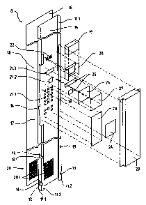
In this lift cage (1) a first side wall element (5), a second side wall
element (6), a third side
wall element (7), a control panel wall element (8) and a back wall element (9)
are
provided as wall elements. The wall elements (5, 6, 7, 8, 9) have, at their
longitudinal
edges, doubly bent-over ends to which the wall elements (5, 6, 7, 8, 9) are
connected by
means of screws or clips. After the mounting of the side wall elements (5, 6,
7, 9) the
control panel wall element (8) is pushed in between the first side wall
element (5) and the
second side wall element (6) from the side of the passenger space. Pins
arranged at first
limbs of the side wall elements (5, 6) engage in horizontal and vertical guide
slots
arranged at limbs of the control panel wall element (8). The control panel
wall element
(8) is in that case guided horizontally during pushing into the wall opening
and
subsequently vertically during dropping down into the end position. The
control panel
wall element (8) together with the side wall elements (5, 6, 7) forms a cage
wall, which is
flat and thus vandal-resistant at the side of the passenger space.

Revendications

Note : Les revendications sont présentées dans la langue officielle dans laquelle elles ont été soumises.


4
We claim:
1. A control panel for a lift cage having floor, ceiling and wall elements
forming a passenger space, the control panel being constructed as one of said
wall elements, said control panel wall element including limbs and being
engageable with adjacent wall elements to form a cage wall, wherein pins are
arranged at adjacent wall elements which are engageable in horizontal guide
slots
and vertical guide slots arranged at the limbs.
2. A control panel according to claim 1, wherein the control panel wall
element is mountable upon the adjacent wall elements from the passenger space
and the control panel wall element and adjacent wall elements form a flat cage
wall bordering the passenger space.
3. A control panel according to claim 2, wherein the control panel wall
element limbs include rearwardly facing limbs located at opposed side edges of
the control panel.
4. A control panel according to claim 1 or claim 2 wherein the control panel
wall element has a call transmitter, a story indicator and a loudspeaker and
that
the control panel wall element has a passenger space face lined by a flexible
film.
5. A control panel according to claim 4, wherein the film has printed indicia
on
a rear side thereof, said indicia being observable from a front side of the
film.
6. A lift cage wall assembly, comprising a pair of spaced wall elements, each
of said wall elements having pins extending outwardly into the space between
the
wall elements; and a control panel having a width corresponding to the space
between the wall elements, the control panel having spaced rearwardly-facing
limbs, and limbs having guide slots comprising vertical and horizontal slot
portions
for engagement with said pins for mounting the control panel between and flush
with said spaced wall elements.

5
7. The wall assembly according to claim 6, wherein said spaced wall
elements each have a rearwardly-directed side limb, the pins being mounted on
said limbs.
8. The wall assembly according to claim 6, wherein the control panel has a
call transmitter, a story indicator and a loudspeaker and that the control
panel wall
element has a passenger space face lined by a flexible film.
9. The wall assembly according to claim 8, wherein the film has printed
indicia
on a rear side thereof, said indicia being observable from a front side of the
film.

Description

Note : Les descriptions sont présentées dans la langue officielle dans laquelle elles ont été soumises.


CA 02231084 2005-12-08
1
Control Panel for a Lift Cage
The invention relates to a control panel for a lift cage consisting of floor,
ceiling and
wall elements.
A cage control panel with a housing made from a U-shaped profile member has
become known from patent specification EP 0 190 407. The housing, consisting
of
side walls and a back wall, is open at the front side of the cage control
panel,
wherein the frontal edges of the side walls are provided with flanges by which
the
housing bears against a wall of the lift cage. Grooves, in which guides are
displaceably inserted, are provided at the inner sides of the side walls.
Mounting
io plates are held at their edges in the guides. Switches for the input of
control
commands, such as cage calls and indicator lamps for the indication of stored
control commands, are fastened to the mounting plates. Microswitches and
luminescent diodes are respectively provided as switches and indicator lamps.
The protruding parts of the housing, thus the switches and the indicator
lamps, are
disadvantageous in the known equipment. The protruding parts represent a risk
of
injury for the lift passengers and promote vandalism.
Here the invention will provide a remedy. In one aspect, the present invention
solves the task of avoiding the disadvantages of the known equipment and
proposes
a control panel which is flush with the cage wall and is easily mountable and
2o demountable.
The advantages achieved by the invention are substantially to be seen in that
the
cage control panel appears as a component of the cage wall. Fastening means
are
not visible externally. Although the control panel is mounted and demounted
from
the side of the passenger space it is not apparent to the lift passengers in
which
manner the control panel is demountable. Vandalism is thereby made impossible.
The control panel can be subsequently mounted and demounted easily and without
great effort during construction of the lift cage or during maintenance
operations.
In one aspect, the present invention resides in a control panel for a lift
cage having
floor, ceiling and wall elements forming a passenger space, wherein the
control

CA 02231084 2006-10-13
la
panel is one of said wall elements, said control panel wall element being
engageable with adjacent wall elements to form a cage wall.
In another aspect, the present invention resides in a lift cage wall assembly,
comprising a pair of spaced wall elements, each of said wall elements having
pins
extending outwardly into the space between the wall elements; and a control
panel
having a width corresponding to the space between the wall elements, the
control
panel having spaced rearwardly-facing limbs, and limbs having guide slots for
engagement with said pins for mounting the control panel between and flush
with
said spaced wall elements.
In a further aspect, the present invention resides in a control panel for a
lift cage
having floor, ceiling and wall elements forming a passenger space, the control
panel
being constructed as one of said wall elements, said control panel wall
element
including limbs and being engageable with adjacent wall elements to form a
cage
wall, wherein pins are arranged at adjacent wall elements which are engageable
in
>> horizontal guide slots and vertical guide slots arranged at the limbs.
BRIEF DESCRIPTION OF THE DRAWINGS
The invention is explained in more detail in the following on the basis of
drawings
illustrating merely an embodiment route. There:

CA 02231084 1998-03-04
2
Fig. 1 shows a lift cage consisting of floor, ceiling and wall elements with a
control panel
wall element,
Fig. 2 shows details of the control panel wall element and
Fig. 3 shows details of the fastening of the control panel wall element.
In Figs. 1 to 3 a lift cage, which is built in element mode of construction
and consists of a
floor element 2 and a ceiling element 3 with bent-over ends 4, to which wall
elements 5,
6, 7, 8 and 9 are fastened, is designated by 1. Not illustrated are the bent-
over ends of
the floor element 2, to which the wall elements 5, 6, 7, 8 and 9 are fastened
in the floor
region. A first side wall element 5, a second side wall element 6, a third
side wall element
7, a control wall element 8 and a back wall element 9 are provided as wall
elements. The
elements of the second side wall and the cage doors of the lift cage are not
illustrated.
The wall elements 5, 6, 7, 8 and 9 have at their longitudinal edges doubly
bent-over ends
10, at which the wall elements 5, 6, 7, 8 and 9 are connected by means of, for
example,
screws or clips. The doubly bent-over ends 10 consist of a first limb 11.1 and
a second
limb 11.2.
After the mounting of the side wall elements 5, 6, 7 and 9 the control wall
element 8 is
pushed between the first side wall element 5 and the second side wall element
6 from the
passenger space. Pins 12 arranged between the first limbs 11.1 of the side
wall
elements 5 and 6 engage in horizontal guide slots 13 arranged at the limbs
11.1 and 11.2
of the control panel element 9 and in vertical guide slots 14. The control
panel wall
element 8 is in that case horizontally guided during pushing into the wall
opening and
subsequently vertically guided during dropping down into the end position.
Thereafter,
the control panel wall element 8 is connected at the upper end with the bent-
over ends 4
of the ceiling element 3. The control panel wall element 8 together with the
side wall
elements 5, 6 and 7 forms a cage wall which is flat at the side of the
passenger space
and thus vandal-resistant.
The control panel wall element 9 consists of a base plate 15, which is lined
at the side of
the passenger space by means of a flexible film 16 and serves as an apparatus
support
for a call transmitter 17, a storey indicator 18 and for a loudspeaker 19.
First perforations

CA 02231084 1998-03-04
3
20.1 at the lower end of the base plate 15 and of the film 16 form a
ventilation opening,
which is designated by 20. The base plate 15 has first recesses 21.1 for the
call
transmitter 17, a second recess 21.2 and a third recess 21.3 for the storey
indicator 18
and a second perforation 22 for the loudspeaker 19. A small plate 23 with, for
example,
microswitches and a small plate 24 with a control circuit are arranged on the
rear side of
the base plate 15. The switches reach into the first recesses 21.1 and are
covered at the
side of the passenger space by the flexible film 16. The film 16 is flexible
to the extent
that, for storey selection, the pressing force exerted on the film 16 actuates
the
corresponding switch. The small plate 23 v/ith the switches and the small
plate 24 with
the control circuit serve for call inputting in the lift cage 1. The storey
indicator consists of
transparent covers 25, a display support 26 and a display 27. A loudspeaker
support 28,
which is arranged at the rear side of the base plate 15 by way of the second
perforation
22, serves for holding the loudspeaker 19. The storey indicator 18 and
loudspeaker 19
inform the lift passengers optically and acoustically, respectively. The call
transmitter 17,
the storey indicator 18 and the loudspeaker 19 are mechanically protected by
means of a
cover 29 fastenable to the second limbs 11.2
In the illustrated example the control panel wall element 8 extends over the
entire cage
height. The control panel wall element 8 can also be made smaller to the
extent that just
the call transmitter 17, the storey indicator 18 and the loudspeaker 19 can be
arranged
thereon.
The flexible film 16 serves not only as lining of the base plate 15, but also
as information
carrier. The designations of the switches, the transport capacity,
manufacturer details,
advertising, etc., are printed on the rear side of the film 16, whereby the
printing on the
user side is abrasion-proof and scratch-proof. The film 16 can be transparent
without
colour or with colour. Material cost and mounting cost for designation labels
can be
avoided by the printed film 16.

Dessin représentatif
Une figure unique qui représente un dessin illustrant l'invention.
États administratifs

2024-08-01 : Dans le cadre de la transition vers les Brevets de nouvelle génération (BNG), la base de données sur les brevets canadiens (BDBC) contient désormais un Historique d'événement plus détaillé, qui reproduit le Journal des événements de notre nouvelle solution interne.

Veuillez noter que les événements débutant par « Inactive : » se réfèrent à des événements qui ne sont plus utilisés dans notre nouvelle solution interne.

Pour une meilleure compréhension de l'état de la demande ou brevet qui figure sur cette page, la rubrique Mise en garde , et les descriptions de Brevet , Historique d'événement , Taxes périodiques et Historique des paiements devraient être consultées.

Historique d'événement

Description Date
Le délai pour l'annulation est expiré 2011-03-04
Lettre envoyée 2010-03-04
Accordé par délivrance 2008-02-12
Inactive : Page couverture publiée 2008-02-11
Inactive : Taxe finale reçue 2007-11-22
Préoctroi 2007-11-22
Un avis d'acceptation est envoyé 2007-07-26
Lettre envoyée 2007-07-26
Un avis d'acceptation est envoyé 2007-07-26
Inactive : Approuvée aux fins d'acceptation (AFA) 2007-06-19
Modification reçue - modification volontaire 2006-10-13
Inactive : Dem. de l'examinateur par.30(2) Règles 2006-05-15
Modification reçue - modification volontaire 2005-12-08
Inactive : Dem. de l'examinateur par.30(2) Règles 2005-06-08
Lettre envoyée 2003-02-07
Exigences pour une requête d'examen - jugée conforme 2003-01-09
Toutes les exigences pour l'examen - jugée conforme 2003-01-09
Requête d'examen reçue 2003-01-09
Demande publiée (accessible au public) 1998-09-06
Inactive : CIB attribuée 1998-07-17
Inactive : CIB en 1re position 1998-07-17
Inactive : CIB attribuée 1998-07-17
Symbole de classement modifié 1998-07-17
Inactive : CIB attribuée 1998-07-17
Inactive : Certificat de dépôt - Sans RE (Anglais) 1998-05-20
Demande reçue - nationale ordinaire 1998-05-20

Historique d'abandonnement

Il n'y a pas d'historique d'abandonnement

Taxes périodiques

Le dernier paiement a été reçu le 2007-02-27

Avis : Si le paiement en totalité n'a pas été reçu au plus tard à la date indiquée, une taxe supplémentaire peut être imposée, soit une des taxes suivantes :

  • taxe de rétablissement ;
  • taxe pour paiement en souffrance ; ou
  • taxe additionnelle pour le renversement d'une péremption réputée.

Les taxes sur les brevets sont ajustées au 1er janvier de chaque année. Les montants ci-dessus sont les montants actuels s'ils sont reçus au plus tard le 31 décembre de l'année en cours.
Veuillez vous référer à la page web des taxes sur les brevets de l'OPIC pour voir tous les montants actuels des taxes.

Historique des taxes

Type de taxes Anniversaire Échéance Date payée
Enregistrement d'un document 1998-03-04
Taxe pour le dépôt - générale 1998-03-04
TM (demande, 2e anniv.) - générale 02 2000-03-06 2000-02-18
TM (demande, 3e anniv.) - générale 03 2001-03-05 2001-02-22
TM (demande, 4e anniv.) - générale 04 2002-03-04 2002-02-28
Requête d'examen - générale 2003-01-09
TM (demande, 5e anniv.) - générale 05 2003-03-04 2003-02-28
TM (demande, 6e anniv.) - générale 06 2004-03-04 2004-02-20
TM (demande, 7e anniv.) - générale 07 2005-03-04 2005-02-23
TM (demande, 8e anniv.) - générale 08 2006-03-06 2006-03-01
TM (demande, 9e anniv.) - générale 09 2007-03-05 2007-02-27
Taxe finale - générale 2007-11-22
TM (brevet, 10e anniv.) - générale 2008-03-04 2008-02-21
TM (brevet, 11e anniv.) - générale 2009-03-04 2009-02-20
Titulaires au dossier

Les titulaires actuels et antérieures au dossier sont affichés en ordre alphabétique.

Titulaires actuels au dossier
INVENTIO AG
Titulaires antérieures au dossier
JOSE LUIS LACARTE ESTALLO
Les propriétaires antérieurs qui ne figurent pas dans la liste des « Propriétaires au dossier » apparaîtront dans d'autres documents au dossier.
Documents

Pour visionner les fichiers sélectionnés, entrer le code reCAPTCHA :


Pour visualiser une image, cliquer sur un lien dans la colonne description du document. Pour télécharger l'image (les images), cliquer l'une ou plusieurs cases à cocher dans la première colonne et ensuite cliquer sur le bouton "Télécharger sélection en format PDF (archive Zip)" ou le bouton "Télécharger sélection (en un fichier PDF fusionné)".

Liste des documents de brevet publiés et non publiés sur la BDBC .

Si vous avez des difficultés à accéder au contenu, veuillez communiquer avec le Centre de services à la clientèle au 1-866-997-1936, ou envoyer un courriel au Centre de service à la clientèle de l'OPIC.


Description du
Document 
Date
(aaaa-mm-jj) 
Nombre de pages   Taille de l'image (Ko) 
Dessin représentatif 1998-09-20 1 6
Description 1998-03-03 3 140
Abrégé 1998-03-03 1 25
Revendications 1998-03-03 1 26
Dessins 1998-03-03 2 41
Description 2005-12-07 4 160
Revendications 2005-12-07 2 49
Revendications 2006-10-12 2 56
Description 2006-10-12 4 172
Dessin représentatif 2007-06-25 1 12
Courtoisie - Certificat d'enregistrement (document(s) connexe(s)) 1998-05-19 1 116
Certificat de dépôt (anglais) 1998-05-19 1 163
Rappel de taxe de maintien due 1999-11-07 1 111
Rappel - requête d'examen 2002-11-04 1 115
Accusé de réception de la requête d'examen 2003-02-06 1 173
Avis du commissaire - Demande jugée acceptable 2007-07-25 1 164
Avis concernant la taxe de maintien 2010-04-14 1 171
Correspondance 2007-11-21 1 45