Note : Les descriptions sont présentées dans la langue officielle dans laquelle elles ont été soumises.
CA 022312~7 1998-03-06
DISPLAY APPARATUS
FIELD OF THE INVENTION
This invention relates to display apparatus generally
and, in particular, to such apparatus having an illuminated
background against which displayed alphanumeric characters, and
graphics symbols are viewed.
BACKGROUND OF THE INVENTION
A plentitude of battery powered, hand-held solid state
devices are provided with disp:Lay screens adapted for specialized
applications. Examples of such devices include, computers,
distance measuring devices, navigational instruments, paging
devices, and communications devices generally, including telephone
handsets adapted to receive e-mail. This list is not exhaustive,
but serves to illustrate the utilitarian nature of alphanumeric,
and graphics display screens which are essential where an
alphanumeric data or graphics readout is required.
Under conditions of sufficient ambient light level, these
screens perform adequately. At low level light conditions,
however, illumination is required to read the data carried by the
2C screen. Where an external power source provides operating current
for the device, screen illumination is not generally a problem.
However where the device relies on a self-contained source of
battery power, illumination becomes problematic since the current
requirements of illumination components generally impose a
CA 022312~7 1998-03-06
substantial current drain from the battery. Light emitting diodes
(LEDs) are particularly notorious in this regard. Power
conservation in battery powered devices of the type described is
therefore a major concern for equipment designers and users alike.
SUMMARY OF THE INVENTION
Having regard to the aforedescribed problem associated
with battery power conservation, a principal provision of the
present invention is display apparatus having a controllable
illumination screen against which opaque symbols formed on a
transparent reflective viewing screen can be viewed.
Another provision of the invention is display apparatus
in which the illumination screen is adapted to be energized
selectively so that only discrete portions provide illumination
for viewing corresponding portions of the viewing screen, and its
opaque symbols.
Yet another provision of the invention is display
apparatus having a positionable cover for covering portions of the
screen that are not viewed, and circuit means responsive to the
cover position that restorably inhibit illumination of a covered
screen portion.
A still further provision of the invention is display
apparatus that embodies sensing devices to extinguish any and all
illuminated regions of the illumination screen in the absence of
data on the viewing screen, when ambient light levels are high, or
when the apparatus is placed within a predetermined distance to a
CA 022312~7 1998-03-06
user, notably when a telephone handset is moved from a read
position to a talk and listen position alongside a user's face.
The problems associated with the prior art may be
substantially overcome, and the foregoing provisions achieved by
recourse to one aspect of the invention which relates to display
apparatus that comprises, in combination, a transparent viewing
screen having a reflective substrate adapted to form transitory
opaque symbols thereon in response to respective ones of input
data signals, means for applying the data signals to selected
portions of the substrate, illumination means disposed in registry
with the screen for backlight:ing the substrate in response to
respective ones of input control signals, and control means
coupled with the illumination means for applying the control
signals thereto to illuminate predetermined portions of the
illumination means against which the symbols on the substrate can
be viewed.
Another aspect of the invention is a method for viewing
a transparent screen having a reflective substrate adapted to form
transitory opaque symbols thereon in response to respective ones
of input data signals, and illumination means positioned in
registry with the screen for backlighting the substrate in
response to respective ones of control signals input to the
illumination means, the method comprising the steps of generating
the control signals in coincidence with the data signals, applying
the data signals to selectecl portions of the substrate, and
applying the control signals to the illumination means
CA 022312~7 1998-03-06
concurrently with the data signals at the substrate for
illuminating discrete predetermined portions of the illumination
means against which corresponding ones of the symbols on the
substrate can be viewed.
A further aspect of the invention is a method for viewing
a transparent screen having a reflective substrate adapted to form
transitory opaque symbols thereon in response to respective ones
of input data signals, and segmented illumination means positioned
in registry with the screen for backlighting a predetermined
portion of the substrate in response to respective ones of control
signals input to the illumination means, the method comprising the
steps of generating the control signals, applying the data signals
to selected portions of the substrate, and applying the control
signals to the illumination means for illuminating a predetermined
segment thereof against which lhe symbols on the substrate can be
viewed.
BRIEF DESCRIPTION OF THE DRAWINGS
The invention will now be more particularly described
with reference to embodiments thereof shown, by way of example, in
the accompanying drawings in which:
Fig. 1 is a perspect:ive view of a wireless telephone
handset embodying display apparatus in accordance with the present
invention;
Fig. 2 is a schematic diagram indicating the relative
positions of viewing, and backlight screens, and an opaque
CA 022312~7 1998-03-06
slidable cover utilized in the handset of Fig. 1;
Fig. 3 is a block diagram of a circuit utilized in the
display apparatus of Fig. 1;
Fig. 4 is a flowchart illustrating an algorithm of an
operating program stored digit,ally in a read-only memory of the
circuit in Fig. 3 for enabling the display apparatus of Fig. 1;
and
Fig. 5 is a flowchart illustrating an algorithm of an
enhanced operating program stored digitally in a read-only memory
of the circuit in Fig.3 for enabling the display apparatus of
Fig.1.
DETAILED DESCRIPTION OF THE PREFERRED EMBODIMENTS
A perspective view of a personal communications device is
illustrated in Fig.1 as a wire:Less telephone handset 10 utilizing
a liquid crystal display (LCD) 11 in accordance with the present
invention. It will be observed that the display 11 is positioned
centrally within a body 12 having a telephone receiver 13 at one
end, and an antenna 14 positioned alongside the body adjacent the
receiver.
A cover 15 is disposed on the opposite end of the body
12, and is slidably positionable along the body in a manner to
cover, and uncover selected portions of the display 11. A
bidirectional sliding relationship between the cover 15, and the
body 12 is indicated by a double-headed arrow 16.
Two miniature mechanical microswitches 17, and 18, of a
CA 022312~7 1998-03-06
type known in the art, are mounted on the body 12 alongside the
display 11 in predetermined relation with the cover 15 as will be
described in greater detail hereinbelow.
The cover 15 functions not only as a dust, and protective
component for the display 11, but also serves as a carrier and
housing for a keypad 20, and a microphone 21 as shown. Although
not illustrated, it will be un~lerstood that the cover 15 includes
a protrusion for activating, i.e., tripping, the switches 17, and
18 at predetermined points along its direction of travel.
The relationship between the display 11, and cover 15 is
shown diagrammatically in Fig. 2 in its simplest form. It will be
apparent therefrom that as the cover 15 is displaced along its
direction of travel, it overlies more or less of the display 11.
A spring-tensioned detent 19 (Fig. 1) of a known design is
lS disposed on the body 12 between the switches, and engages
cooperatively with the aforementioned cover protrusion to
releasably hold the cover open approximately mid-way of its
travel.
It will be understoocl from Fig. 2, that the display 11
comprises a transparent reflective substrate which functions as a
viewing screen 25 in registry with, and overlying a backlight
illumination screen 26. Although the screen 26 is shown in two
parts for illustrative purposes as a first backlight segment 27,
and a larger second backlight: segment 28, it could readily be
fabricated as a unitary structure.
A major consumer of power from an on-board battery (not
CA 022312~7 1998-03-06
shown) that powers the handset 10, and its circuits, are the
segments 27 and 28 which permit viewing the screen 25 during
periods of low level ambient light. A significant feature of the
embodiments herein described, permits such screen viewing while
maximising battery service life.
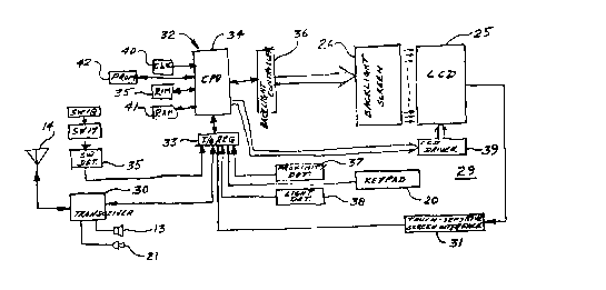
A detailed block diagram of a circuit 29 ~Fig. 3)
utilized in the handset 10 ,hows that data appearing on the
display 11 has its origin in several sources. One source is from
the keypad 20 when a telephone call is placed. Thus, a telephone
directory number entered by the keys is first displayed to the
caller for confirmation before transmitting the number via a
transceiver 30, and its antenna 14, to a local telephone central
office or relay station. A second source is service data, and
graphics, received by the transceiver 30 from the central office
or relay station, which is viewed on the display 11 during call
reception. Additionally, the screen 25, shown in Fig. 3 as a
known touch-sensitive screen displaying easily understood prompts,
and responding to a writing stylus, provides another data input
source via a screen interface 31. The microphone 21 may also be
utilized in handsfree dialing, employing suitable known software,
whereby spoken commands could invoke dialing a directory number,
for example, of anyone listed in a personal directory stored
digitally in memory at the handset 10.
Data, including graphics, from at least one of the
aforenoted sources is received at a microprocessor 32 via an I/O
register 33 and is coupled the:refrom to a central processing unit
CA 022312~7 1998-03-06
(CPU) 34. Under control of an operating program stored digitally
in a read-only memory (ROM) 35, the CPU 34 produces two outputs.
A first output is coupled to an input of a backlight controller 36
that functions to enable and i:Lluminate predetermined segments of
the backlight screen 26. In this regard, another input to the
register 33 is from a switch engagement detector 35 that senses
activation of the switches 17, and 18 by the cover 15. An output
from the detector 35 is coupled to the CPU 34 via the register 33,
and is recognized as either a blanking or illumination signal that
results in an output to the controller 36 which correspondingly
disables or enables either one or both of the segments 27, and 28
depending upon the position of the cover 15.
In keeping with the objectives of the invention, a
proximity detector 37 is employed to sense the placement of the
handset 10 against a user's face during a call in progress. In
this position the screen 25 would not be visible to the user, so
that both segments 27, and 28 may be blanked. The detector 37
thus outputs a signal to an input port of the register 33 which is
then applied to the CPU 34 to control the controller 36 in
restorably disabling both segments 27, and 28. A suitable
detector 37 is disclosed in pending United States patent
application entitled, Safety Switch for Communication Device,
filed 14 March 1996 under serial number 08/615,908 in the name of
André Van Schyndel, and assigned to the same assignee as in the
present application. The disclosure of Van Schyndel is
incorporated herein by reference.
- 8
CA 022312~7 1998-03-06
A light level detector 38 also functions to disable the
segments 27, and 28 when a backlight is not required. This
situation arises under normal light levels when the opaque symbols
appearing on the screen 25 are readily observable without
5 backlight illumination. The detector 38 is thus set to respond to
a predetermined light level so that ambient illumination of
adequate intensity results in an output signal to an input port of
the register 33. An output therefrom is coupled to the CPU 34
which signals the controller 36 to generate a disabling or
lC blanking signal that is applied to the screen 26.
A second output from the CPU 34 is applied to a liquid
crystal display (LCD) driver 39 that activates predetermined
portions of the screen 25 on which corresponding opaque symbols
are formed. It will be understood that the opaque symbols are in
overlying registry with the illuminated portions of th~-screen 26,
against which the symbols are viewed under low light level
conditions.
Typically, the microprocessor 32 includes timing means,
shown as a clock 40, and a random access memory (RAM) 41 utilized
in processing data received at the CPU 34 from the register 33.
Additionally, a programmable read-only memory (PROM) 42 functions
in a known manner to store digitally a personal directory for
frequently called numbers.
One embodiment of the invention is defined by an
operating program developed from an algorithm illustrated in the
flowchart of Fig. 4 and stored digitally in the ROM 35 for
g
CA 0223l2~7 l998-03-06
enabling the CPU 34. In this embodiment, illumination of the
screen 26 iS effected by means of individual ones of the segments
27, and 28. Reduced efficiency may be expected, however, inasmuch
as an entire segment is illuminated at one time, even though only
5 a portion of that segment may be required to backlight data
carried by the screen 25.
Reference to Fig. 4 reveals a start block 45 from which
the algorithm proceeds to a decision block 46 at which it is
determined if there is sufficient viewing light for the screen 25.
Under adequate light conditions, screen 26 illumination is
disabled (block 47) by the controller 36 in response to a signal
from the CPU 34, triggered by the output from the detector 38 as
described.
When light level is insufficient, a following test in
block 48 determines if screen data has been coupled to the driver
39. A negative result confirms disabling screen 26 illumination,
whereas an affirmative conclus:ion results in a test at block 49 to
determine if the detector 37 has been activated due to close
proximity of the handset to a user's face. A positive result
confirms disabling screen 26 illumination, but a negative response
leads to a subsequent test in block 50 to ascertain the condition
of the switch 18. If the switch 18 iS not released from
activation by the protrusion of the cover 15, the screen 26
remains disabled since the cover is understood to be closed.
2c However, a released switch 18 rneans that the cover 15 iS at least
partially open. Consequently, the segment 27 iS enabled for
- 10
CA 0223l2~7 l998-03-06
backlighting the upper portion of the screen 25 as indicated in
block 51. Backlit data displayed on the screen 25 iS shown in
block 52.
A following test in block 53 determines if the switch 17
has been released from activation by the cover 15. If released,
the segment 28 iS illuminated (block 54) to backlight the lower
portion of the screen 25, thereby completely illuminating the
screen 25. Block 55 shows data being displayed on the backlit
screen 25. An activated switch 17, however, results in the
segment 28 being disabled according to block 56.
Depending upon the position of the cover 15 with respect
to the switches, the screen 25 may be either partially or entirely
backlit by the segments 27 and 28. Thus, if the switches 17, and
18 are sequentially actuated by the cover 15, the screen 25 iS
completely covered. Both segments 27, and 28 are consequently
disabled to conserve battery power. Conversely, when the switch
18 iS released, this indicates that the upper portion of the
screen 25 iS uncovered. Accordingly, the segment 27 iS enabled as
described to provide backlighting for alphanumeric data, and
graphics appearing on the corresponding upper portion of the
screen 25. Since, however, the segment 27 of the present
embodiment is smaller in area than the segment 28, data
accommodated by the upper portion of the screen 25 will be reduced
in scope. The smaller segment 27 thus functions to provide
adequate backlighting under low level ambient light conditions
while conserving battery power for short messages, graphics, and
CA 0223l2~7 l998-03-06
the like which require only a portion of the screen 25.
When a message sequence or graphics display is greater in
size than can be accommodated by the uncovered upper portion of
the screen 25, the switch 17 iS released, and the cover 15 iS then
5 in its most extended position as illustrated in Fig. 1. It would
be apparent to the user to slide the cover 15 to its most extended
position to view either a long message or other alphanumeric data
or graphics information which require greater screen space than
that provided by the screen 25 when backlit by the segment 27. In
this event, both segments 27 and 28 are energized to backlight the
entire screen 25.
Fig. 5 iS a flowchart illustrating an algorithm of an
enhanced operating program stored digitally in the ROM 35 for
enabling the CPU 34 to give effect to a preferred operating mode
of the circuit 29 in Fig. 3. This embodiment provides dynamic
control of the screen 25, together with the screen 26, such that
only individual ones of opaque symbols, or characters, formed on
the screen 25 are selectively illuminated with backlight. In this
manner the objective of the invention to maximize the service life
of an on-board battery is most effectively achieved.
Having regard to Fig. 5, it will be observed that the
algorithm of blocks 60-66 corresponds substantially with the
algorithm of blocks 45-51 in F:ig. 4. Divergence begins, however,
in block 67 of Fig. 5 at which the controller 36 iS enabled by the
CPU 34 to configure the screen 26 for illuminating predetermined
discrete elements thereof. This is followed by block 68 at which
CA 022312~7 1998-03-06
screen data is output from the driver 39 to the screen 25.
Control signals output from the CPU 34 to the controller 36 are
generated by the CPU in coincidence with corresponding data
signals that are coupled to the driver 39. Resulting drive
5 signals output from the controller 36 to the screen 26, and
corresponding data signals output from the driver 39 to the screen
25, are therefore applied to their respective screens
concurrently, and in registrat:ion. Elements of the screen 25 that
form the transitory opaque symbols, which correspond to individual
ones of the data, are consequently backlit by corresponding
illumination elements of the screen 26 via the controller 36 in
accordance with block 69. It will be understood that the condition
of the switch 17 is immaterial in the preferred operating mode of
the circuit 29 in view of the one-on-one relationship between data
and its backlighting. Accordingly, the switch 17 is not used, and
the algorithm proceeds to block 70 where all backlit data are
displayed on the screen 25.
The embocliments of the present invention rely on a block
diagram to describe various elements and their respective
functions in the circuit 29 which is programmable to define
individually the embodiments disclosed. Although program listings
have not been included to disclose the precise manner of digital
computer programming to perf-orm the operations desired, the
detailed functional descriptions presented herein, together with
related flowcharts, would permit a skilled computer programmer to
program the CPU 34 to perform all required operations.
- 13 -
CA 022312~7 1998-03-06
Accordingly, the foregoing constitutes a sufficient description to
such individuals for a comprehensive understanding of the best
mode contemplated to give effect to the embodiments as disclosed
and claimed herein.
To those skilled in the art to whom this specification is
addressed, it will be apparent that the embodiments aforedescribed
may be varied to meet particular specialized requirements without
departing from the true spirit and scope of the invention
disclosed. For example, although the invention is described in
lC the context of a wireless telephone handset 10, the invention may
be readily applied to any one of the aforementioned solid state
devices having a display screen. Furthermore, the mechanical
microswitches 17, and 18 may be replaced with reed switches that
are activated by a magnetic element disposed within the cover 15
1~ instead of the aforementioned protuberance. Alternatively, the
reed switches could be replaced with solid state magnetic flux
detectors. The foregoing embodiments are therefore not to be
taken as indicative of the limits of the invention, but rather as
exemplary structures thereof which are described by the claims
appended hereto.