Note : Les descriptions sont présentées dans la langue officielle dans laquelle elles ont été soumises.
CA 02231399 1998-03-09
WO 97/10412 PCT/US9b/12909
-1-
The present invention relates to a tool for
blocking axial flow through a gravel-packed well annulus
and in one of its aspects relates to a tool having by-
t
passes for gravel-packing multi-zones within a completion
interval in a single operation which allows the gravel be
adequately distributed over the interval but will block any
substantially axial flow through the gravel-packed annulus
between productive zones of the interval after the gravel
has been placed.
In producing hydrocarbons or the like from
unconsolidated and/or fractured subterranean formations, it
is common to produce large volumes of particulate material
(e.g. hereinafter referred to as 'sand") along with the
formation fluids. If not controlled, this produced sand
can cause a variety of problems which, in turn, adds
substantially to the operating costs and downtime of the
producing well. Therefore, it is extremely important to
control the production of sand in such operations.
"Gravel packing" is probably the most common
technique used for controlling the production of sand from
a well. In a typical gravel pack completion, a screen or
the like is lowered into the wellbore and positioned
adjacent the interval of the well which is to be completed.
Particulate material, collectively referred to as gravel,
is then pumped in a liquid slurry down a workstring and
into the well annulus surrounding the screen.
The liquid in the slurry is "lost" into the
formation and/or flows through the openings in the screen
which results in the gravel being deposited or "screened
out" in the annulus around the screen. The gravel is sized
so that it forms a permeable mass between the screen and
the producing formation which allows flow of the produced
fluids therethrough and into the screen while substantially
blocking the flow of any particulate material ("sand")
therethrough.
CA 02231399 2002-02-12
-2-
A major problem associated with gravel packing,
especially where thick or inclined production intervals are
to be completed, is the poor distribution of gravel (i.e.
incomplete packing of the interval resulting in voids in
the gravel pack) which is often caused by the premature
loss of liquid from the gravel slurry into the formation.
This fluid loss can cause "sand bridges" to from in the
annulus before all of the gravel has been placed. These
bridges block further flow of the slurry through the well
annulus thereby preventing the placement of sufficient
gravel (a) below the bridge for top-to-bottom packing
operations or (b) above the bridge, for bottom-to-top
packing operations.
Recently, well tools have been developed for
providing a good distribution of gravel throughout the
desired interval even where sand bridges may form in the
annulus before all the gravel has been deposited. These
tools (e. g. well screens) include a plurality of "alternate
flowpaths" (e. g. perforated shunts or conduits) which
extend along the screen and receive gravel slurry as it
enters the wellbore annulus. If a sand bridge forms before
all of the gravel is placed, the slurry will by-pass the
sand bridge and will flow out through the spaced
perforations in the shunt conduits at different levels
within the annulus to thereby complete the filling of the
annulus above and/or below the bridge. For complete
details of such well tools; see U.S. Patents 4,945,991;
5,082,052; 5,113,933; and 5,333,688,
~ Well tools having alternate flowpaths such as
those described above have proved successful in completing
relatively thick wellbore intervals (i.e. 100 feet or more)
in a single operation. However, there is still a problem
in completing these thick intervals even where good gravel
distribution is initially achieved: this problem being due
to the fact that certain zones within the interval are
likely to "water-out" before other productive zones. When
CA 02231399 1998-03-09
WO 97/10412 PCT/US96/12909
-3-
this occurs, the watered-out zones) will produce
substantially only water which is obviously undesirable and
economically unacceptable. Therefore, it is desirable to
block flow from such watered-out zones) while continuing
the production only from the more productive zones.
Typically, when a zone begins to produce
unacceptable amounts of water, flow into the well screen
adjacent that zone is blocked (e.g. by cementing, closing a
sliding sleeve, or the like) as will be understood by those
skilled in the art. While this prevents flow of water into
the screen adjacent the watered-out zone, unfortunately,
water from the watered-out zone can still flow through the
gravel-packed annulus and into the screen adjacent the
still productive zones(s). Accordingly, when a thick
wellbore interval is gravel packed, it is important that
axial flow through the annulus between the different zones
be substantially restricted once the flow from a watered-
out zone into the screen is blocked.
Before the development of the "alternate
flowpath" technology, a series of individual operations was
used to gravel-pack thick, wellbore interval. That is, a
first zone would be isolated with packers or the like and
then gravel-packed after which a second zone would be
isolated and gravel-packed, and so forth, until the entire
interval was completed. The packers used to isolate the
zones were left in place which also served to block axial
flow through the well annulus between the individually
packed zones so that when the flow of water was blocked
into the screen adjacent a watered-out zone, it could not
flow through the annulus into the screen adjacent a still
producing zone.
With the advent of "alternate flowpath"
technology wherein a thick interval can be gravel-packed in
a single operation, the individual zones no longer have to
be packed off to accomplish a good disbursement of gravel
throughout the interval. However, there still exists the
need for blocking flow through the annulus between the
CA 02231399 1998-03-09
WO 97/10412 PCT/ITS96/12909
-4-
zones in a thick interval.
The present invention provides a well screen for
gravel-packing an interval within a wellbore which is
comprised of at least two joints connected by a well tool.
each joint is comprised of a length of screen section which
h.as at least one, axially-extending shunt conduit thereon
for carrying gravel slurry to different levels within the
interval.
The well tool has at least one by-pass tube
therein which is adapted to align with and connect the
shunt conduits on the respective joints of the well screen
whereby gravel slurry can flow from one of the shunt
conduit, through the by-pass tube, and into the other shunt
conduit. A means, e.g. cup packers, is mounted on the well
tool for preventing axial flow of fluids past the tool when
the well screen is in an operable position within the
wellbore whereby flow cannot occur through the well annulus
between zones after the interval has been gravel-packed.
More particularly, the present well screen is
comprised of a plurality of similar lengths or '°joints'°,
each of which is comprised of a length of section of
screen. As used herein, "screen" is intended to mean any
fluid-permeable structure commonly used in gravel pack
operations; (e.g. commercially-available screens, porous or
permeable pipe, slotted or perforated liners or pipes,
screened pipes, prepacked screens and/or liners, or
combinations thereof). Axially-extending along the length
of each joint is at least one alternate flowpath (e. g.
slhunt tubes or conduits).
A well tool comprised of a central conduit, with
or without a polished or profiled internal diameter (ID),
having connector means thereon (i.e. threaded coupling and
external threads) connects the respective ends of joints
together. A sleeve is concentrically mounted on the
outside of said conduit with at least one by-pass tube
positioned within the annulus between the conduit and the
sleeve. The by-pass tubes a~~e spaced to align with and
CA 02231399 1998-03-09
WO 97/10412 PCT/US96/12909
-5-
fluidly-connect respective shunt tubes on adjacent joints
together when the tool is assembled.
Mounted onto sleeve is a packing means which is
preferably comprised of two sets of cup packers with backup
rings; one set having one or more upwardly-facing cup
packers and the other set having one or more downwardly-
facing cup packers. Also, positioned on the sleeve between
the sets of cup packers is a multi-bladed centralizer.
To assemble the well screen, the well tool is
connected to respective ends of two adjacent joints of well
screen and is properly torqued to axially align each by-
pass tube within the well tool with the respective shunt
tubes on each of the joints. Next, the respective by-pass
tubes and the aligned shunt conduits are fluidly connected
together by appropriate connectors.
In operation, the well screen is lowered on a
workstring and is positioned so that packer means on the
well tool will lie within the interval to be gravel-packed.
A gravel slurry is pumped into and down the workstring and
into the well annulus around the well screen. The gravel
flows through the shunt conduits on one of the joints,
through the by-pass tubes in the well tool, and through the
respective shunt conduits on the other joint to provide a
good distribution of gravel throughout the interval.
When a zone within the interval 'waters-out",
flow from that zone into well screen normally will be
blocked (e. g. by cementing, closing an appropriate sliding
sleeve, or the like) as will be understood by those skilled
in this art. The Backing means on the well tool prevents
any substantial flow through the annulus between zones
thereby preventing the water from the watered-out zone from
flowing through the annulus into the well screen adjacent
to a zone that is still under production.
BRTEF DESCRIPTION OF THE DRAWINGS
The actual construction, operation, and apparent
advantages of the present invention will be better
understood by referring to the drawings which are not
CA 02231399 1998-03-09
WO 97/10412 PCT/LTS96/12909
~-6-
necessarily to scale and in which like numerals identify
like gars and in which:
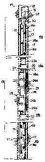
FIG. 1 is a broken-away, elevational view, partly
in section, of the present well tool incorporated into a
well screen having alternate flowpaths which has been
installed into a well bore; and
FIG. 2 is an enlarged, elevational view, partly
in section, of the well tool of FIG. 1.
BEST KNOWN MODR F(~R rnnvwrrTr_ nrTm THF Ijvjp NTTnN
Referring more particularly to the drawings,
FIG.1 illustrates the lower end of a wellbore 10 having a
casing 11 extending through a production interval 12 which
is to be gravel packed. Casing 11 has perforations 13
adjacent at least tow productive zones 14a, 14b of the
subterranean productive formations) which forms interval
7.2. Well screen 15 is positioned within the wellbore 10
and extends through interval 12.
More particularly, well screen 15 is shown as
being comprised of a plurality of lengths or "joints°' 16
which are substantially similar in basic construction (only
part of two adjacent joints 16a, 16b are shown in FIG. 1).
Fach joint is comprised of a length or section of screen 17
o~r the like. The term ''screen" is used generically herein
and is meant to include and cover any and all types of
permeable structures commonly used by the industry in
gravel pack operations which permit flow of fluids
therethrough while substantially blocking the flow of
particulates (e. g. commercially-available screens, slotted
or perforated liners or pipes, screened pipes, prepacked
screens, porous or permeable pipes, and/or liners, or
combinations thereof). Also, as will be understood in this
art, some or all of the joints may also include lengths)
or blank pipe (not shown) in addition to the screen section
if a particular operation so dictates.
Positioned on each joint 16 is at least one
perforated, shunt tubes or conduits 18 (e. g. four, radially
CA 02231399 1998-03-09
WO 97/10412 PCT/US96/12909
-7
spaced at 90° intervals) which are parallel to each other
and which extend axially along the entire length of joint
. 16. Shunt conduits) 18 may be extend either externally
along joint 16 (as shown) or internally of joint 16 and/or
screen section 17 (not shown) or both.
Coupled into well screen 15 between joints 16a,.
16b is well tool 20 in accordance with the present
invention. Tool 20 is comprised of a central conduit 21
with or without a polished or profiled ID which has
appropriate connector means thereon (i.e. threaded coupling
22a and external threads 22b) for connecting tool 20 to the
respective ends of adjacent joints 16a, 16b. A sleeve 23
is mounted on the outside of said conduit 21 to provide a
space therebetween. At least one by-pass tube 25 (i.e. the
same numbers as the number of shunt tubes 18 on each
respective joint 16) are positioned within this space. The
by-pass tubes) is arranged to align with respective shunt
tubes 18 on joints 16 when tool 20 is assembled. Each by-
pass tube 25 extends completely through sleeve 23 so that
the respective ends of each tube is exposed for a purpose
discussed below.
Mounted onto the external surface of sleeve 23 is
packing means 26. Preferably, packing means 26 is
comprised of two sets of cup packers with backup rings 27
(e. g. Guiberson "CP" Cups, Guiberson/Dresser Industries,
Houston, TX); one set having one or more (two shown)
upwardly-facing cups 26a and the other set having one or
more downwardly-facing cups 26b. Positioned on sleeve 23
between the sets of packers is a multi-bladed centralizer
28 (four blades at 90° intervals are shown).
To assemble well screen 15, the respective
connector means 22 of well tool 20 are connected to the
respective ends of two adjacent joints 16 and are properly
torqued so that each by-pass tube 25 is axially-aligned
with a respective shunt tube 18 on each of the joints 16a,
16b. Next, the ends of each by-pass tube 25 are fluidly-
connected to the ends of respective, aligned shunt conduits
CA 02231399 2002-02-12
-8-
by either separate, individual connectors (not shown) or by
a single connector 30 (see US Patent 5,390,966:).
In operation, once well screen 15 has been
assembled, it is connected onto the lower end of workstring
31 and is lowered into wellbore 10 and positioned so. that
packer means 26 will lie between zones 14a, 14b of
production interval 12. Interval 12 is then gravel-packed
from the"top down" or from the "bottom up" as the case may
be. For example, a gravel slurry is pumped down workstring
31, out ports 32 in "cross-over" 33, and into the top of
well annulus 35 below packer 26. The gravel fills the
annulus 35a above packing means 26 either directly and/or
through the perforations in shunt tubes 18 even if a "sand
bridge" occurs before the operation is complete.
Slurry also flows through shunt tubes 18a,
through by-pass tubes 25, and out shunt tubes 18b to fill
the well annulus 35b which lies below packing means 26. Of
course, in some instances, circulation of the gravel slurry
can be reversed to fill the annulus from the "bottom up" if
desired. In any event, the by-pass tubes 25 in tool 20
allows slurry to flow past packer means 26 during the
gravel pack operation so that a good gravel distribution is
obtained over the entire interval 12.
As will be understood in the art, either zone 14a
or 14b may "water-out" before the other zone so that
substantially only water will be produced form the watered-
out zone. At this point in the operational life of the
well, flow from the watered-out zone into well screen 15
will normally be blocked (e.g. by filling the lower end of
well screen 15 with cement, closing a sliding sleeve, or
the like). In the past without the present tool 20,
substantial flow of water could still occur through the
highly-permeable, gravel-packed well annulus surrounding
the well screen. Accordingly, water could flow up annulus
35 and enter unblocked, well screen 15 adjacent the still
producing zone 14a or 14b, as the case may be. However,
CA 02231399 1998-03-09
WO 97/10412 PCT/US96/12909
_g_
with well tool 20, even through a small volume of water
(e. g. 10~ of normal flow) may flow between zones through
the gravel-filled shunt tubes) 18 and by-pass tubes) 25,
packing means 26 prevents any substantial flow in the
annulus between zones in either direction (i.e. cups 26a
prevent downward flow while cups 26b prevent upward flow)
whereby any substantial flow from the watered-out zone
cannot enter the well screen adjacent the still producing
zones.