Note : Les descriptions sont présentées dans la langue officielle dans laquelle elles ont été soumises.
CA 02232101 1998-03-13 C~
DISPERSION COMPENSATING OPTICAL FIBER, AND WAVELENGTH
DIVISION MULTIPLEX LIGHT TRANSMISSION LINE USING THE SAME
Field of the Invention
The present invention relates to a dispersion
compensating optical fiber which is connected to a single-
mode optical fiber having zero dispersion in the wavelength
band of 1.3 y m, so as to perform a function of compensating
dispersion in an optical signal in the wavelength band of 1.55
~ mwhichistransmittedthroughthesingle-modeopticalfiber,
while serving as a transn-ission optical fiber. The present
inventionalsorelatestoawavelengthdivisionmultiplexlight
transmissionlineusingsuchadispersioncompensatingoptical
fiber.
Background of the Invention
As a transmission network for optical communication,
single-mode optical fibers having zero dispersion in the
wavelength band of 1.3 ~ m are installed all over the world.
In recent years, as the information-oriented society has
developed, the quantity of communication information has been
dramatically increasing. The explosion of the quantity of
information has made wavelength division multiplex
transmission (WDM transmission) widely accepted in the field
CA 02232101 1998-03-13
of comm~mication. Now, the world is in the age of wavelength
division multiplex transmission. Wavelength division
multiplex transmission is a method in which a wavelength for
optical communication is divided into a plurality of
wavelengths to transmit a plurality of optical signals instead
of using only one wavelength for optical communication, and
therefore, is a light tr2Lnsmission method which is suitable
to large-capacity high-speed communication.
However, in general, the installed single-mode
transmission optical fibe:es which have zero dispersion at 1.31
,u m have a large transmission loss. Hence, when wavelength
division multiplex opticaLl communication is to be realized
using th~e wavelength band of 1.3 ~ m, since the wavelength range
of the installed single-mode transmission optical fibers does
not matc:h a wavelength banclof 1.55 ~ m which is a gain bandwidth
of a regular light amplifier, the light amplifier can not be
used an~1 long-distance optical communication is troubled
accordingly. Due to this, :in recent years, wavelength division
multiplex optical communication is conducted in the wavelength
band of :l.55 ,u m using the installed single-mode transmission
optical fibers which have zero dispersion in the wavelength
band of 1.3 ,u m.
However, when optical communication is conducted in the
CA 02232101 1998-03-13
wavelength band of 1.55 f~ m using a single-mode transmission
optical fiber which has zero dispersion at 1.31 f~ m, since the
installed single-mode t:ransmission optical fibers have
positive dispersion and a positive dispersion slope in the
wavelength band of 1.55 ,u m, as optical signals propagate
through the single-mode transmission optical fiber, the signal
at each one of the wavelenc~th division multiplexed wavelengths
disperse largely. This makes it difficult to separate the
signals at a receiving end, degrades the cluality of the optical
communication, and impairs the reliability of the optical
communic atlon.
To solve such problems, dispersion compensating optical
fibers have been developed recently. A dispersion compensating
optical fiber has negat:ive dispersion. If a dispersion
compensating optical fiber is connected to a receiving end of
a single-mode transmission optical fiber, positive dispersion
of optical signals which propagate through the single-mode
transmic,sion optical fiber is reduced by the negative
dispersion of the dispersion compensating optical fiber so that
the optical signals are received at the receiving end as they
have substantially zero dispersion. As a dispersion
compensating optical fiber is connected to a single-mode
transmission optical fiber in this manner, it is possible to
CA 02232101 1998-03-13
separate the respective wavelength division multiplexed
optical signals at a receiving end, and therefore, a dispersion
compensating optical fiber is expected to realize large-
capacity high-speed communication of a high cluality.
This type of a dispersion compensating optical fiber is
formed as a module. It :is a common practice to connect a
dispersion compensating o]?tical fiber which is formed as short
as possi.ble to a receiving end of a single-mode transmission
optical fiber for the pur]?ose of compensation of dispersion.
Object and Summary of the Invention
However, to form a dispersion compensating optical fiber
as a module and compensate dispersion withLa short fiber length,
it is necessary that the module of the dispersion compensating
optical fiber has high negative dispersion and negative
dispersi.on slope.
Despite this, a dispersion compensating optical fiber
can not k,ave high negative dispersion and a negative dispersion
slope unless very strict conditions regarding various
parameters are met which define a distribution of the
refractive index of the dispersion compensating optical fiber,
which makes it difficult to fabricate the dispersion
compensating optical fiber. Further, when a dispersion
compensating optical fiber has a refractive index
CA 02232101 1998-03-13
configuration which enables high negative dispersion and a
negative dispersion slope, a non-linear phenomena easily
occurs, wherebyamodefie]ddiameter (MFD) oftheopticalfiber
is reduced. If the non-linearity occurs, the waveforms of
signals deform, which is a new problem against an effort to
increase the speed and t:he capacity of wavelength division
multiplex light transmission.
If thespecificrefri~ctionindexdifferenceofthecenter
core becomes too large in line with such a structure where the
mode field diameter of optical fibers is reduced, a lowering
of the t:ransmission quality results from a non-linearity, and
a large transmission loss is created when the optical fiber
is bent.
Meanwhile, other proposed method is to conduct light
transmission using a dispersion shifting optical fiber whose
zero dispersion wavelengt:h is shifted to 1.55 ~ m from 1.31
~ m. While signal transmission without dispersion is possible
when a dispersion shift:ing optical fiber which has zero
dispersion at the wavelength of 1.55 ~ m is used for
transmission of optical signals without dispersion by means
ofthewavelengthofl.55 ~ m, ifwavelength divisionmultiplex
light transmission is conducted using a signal which is in the
wavelength band of 1.55 ~rn, signals at other wavelengths near
CA 02232101 1998-03-13
1.55 ~ m disperse although no dispersion occurs at the
wavelength of 1.55 ~ m. Thus, this light transmission method
is not suitable to lar~e-capacity high-speed wavelength
division multiplex optica:Lcommunication. Moreover, this type
of a dispersion shifting optical fiber has a further problem
that the non-linearity easily occurs.
Conversely, a single-mode optical fiber which has zero
dispersion at the wavelencrth of 1.31 ~ m is excellent in terms
of low non-linearity. Hence, it is ideal to use the installed
single-mode transmission optical fibers which have zero
dispersion at the wavelength of 1.31 ~ m as light transmission
lines, connect dispersion compensating optical fibers which
have low non-linearity and a large mode field diameter to the
single-mode transmission optical fibers and conduct
wavelength division multiplex light transmission using the
wavelengths in the bandwidth of 1.55 ~ m with substantially
zero dispersion.
Noting this, the inventor of the present invention has
conceived the present invention from the conventional idea of
simply forming a dispersion compensating optical fiber as a
module and using the module as an optical fiber which only
compensatesdispersion.Ai-irstobjectofthepresentinvention
is to provide a dispersion compensating optical fiber which
CA 02232101 1998-03-13
is formed in substantial:Ly the same length as a single-mode
light transmission optical fiber and is connected to the
dispers:ion compensating optical fiber so that the dispersion
compensc~tingopticalfiberperformsafunctionoftransmitting
optical signals over a long distance while compensating for
dispers:ion of the optical signals which propagate through the
single-rnode transmission optical fiber, i.e., so that the
dispers:Lon compensating optical fiber has both the function
of compensation of dispersion and the function of light
transmission.Further,asecondobjectofthepresentinvention
is to provide a wavelength division multiplex light
transmissionlinewhichisrealizedbyconnectingasingle-mode
transmission optical fiber and the dispersion compensating
optical fiber described c~bove to each other.
To achieve the objects above, thepresent invention uses
the following means. That is, according to a first aspect of
the present invention, in a dispersion compensating optical
fiber whichis connected to a single-mode transmission optical
fiber which has zero dispersion in the wavelength band of 1.31
m and which transmits optical signals, the means for solving
~he problems is a structu~e that a dispersion value ~ at the
wavelens~th of 1.55 ~ m is in the range of -20ps/nm/km ~ ~ ~ -
lOps/nm/km and that a ratlo of the dispersion value to a
CA 02232101 1998-03-13
dispersi.on slope in the wavelength band of 1.55 ~ m is set to
be subst:antially ec~ual in the absolute value but with the
opposite sign to a ratio of a dispersion value to a dispersion
slope of the single-mode optical fiber in the same wavelength
band of 1.55 ~ m.
Further, according to a second aspect of the present
invention, in a dispersion compensating optical fiber which
has the structure according to the first aspect, the means for
solving the problems is a structure of which a side core which
has a low index of refraction is disposed around a center core
which has the highest inclex of refraction, and a clad which
has a lower index of refraction than that of the center core
but a higher index of refraction than that of the side core
is disposed around the side core so that a distribution of the
refracti.ve index has a W--type profile.
Fu.rther, according to a third aspect of the present
invention, in a dispersicn compensating optical fiber which
has the structure according to the second aspect, the means
for solving the problems is a structure of which a specific
refracti.ve index difference ~+ of the center core from the
clad is in the range of 1.0% and 1.8%, a ratio R A (R ~=~
-/~+) of aspecificrefractiveindex difference ~-oftheside
core from the clad to the specific refractive index difference
CA 02232101 1998-03-13
~+ of the center core from the clad is ecfual to or smaller
than -0 25, and that a ratio Ra (Ra=a/b) of a diameter a of
the center core to a diameter b of the side core is in the range
of 0.3 and 0.4.
F~lrther, according to a fourth aspect of the present
invention, in a dispersion compensating optical fiber which
has the structure according to the first, the second or the
thirdaspect, the means forsolving the problems is astructure
that a rnode field diameter is ecIual to or larger than 6
m.
Further, a fifth aspect of the present invention is
directecltoawavelength divisionmultiplexlighttransmission
linewhi,~hisrealizedbyconnectingasingle-modetransmission
optical fiber which has zero dispersion in the wavelength band
of 1.31 ~ m to a dispersion compensating optical fiber which
is substantially the same length as the single-mode
transmission optical fiber, and the means for solving the
problem~ is a structure that the dispersion compensating
optical fiber is formedby the dispersion compensating optical
fiberaccordingtoeitherc)neofthe firstto the fourthclaims.
In the present invention, a wavelength division
multiplex light transmission line is realized by connecting
a single-mode optical fiber which has zero dispersion in the
CA 02232101 1998-03-13
1.3,u m-wavelength band (more specifically, at the wavelength
of 1.31 ~u m) to the dispersion compensating optical fiber
according to the present i.nvention which is substantially the
samelengthasthesingle-modetransmissionopticalfiber.When
wavelength division multiplex light transmission is conducted
with such a wavelength division multiplex light transmission
line usi.ng optical signal.s which are in the wavelength band
of 1.55JU m, each wavelength in the wavelength band of 1.55
~u m hasi.ncreasingly larger positive dispersion as the optical
signals propagate throu.gh the single-mode transmission
optical fiber.
Th.e optical signals at the respective wavelength
divisionmultiplexedwave].engthsaretransmitted, propagating
from th.e single-mode optical fiber to the dispersion
compensa.ting optical fiber. A dispersion value ~ of the
dispersion compensating cptical fiber is relatively low and
negative, in the range of -20ps/nm/km ~ ~ ~ -lOps/nm/km, and
a ratio of the dispersion value to a dispersion slope of the
dispersion compensating optical fiber in the wavelength band
of 1.55,u m is set to be substantially equal in the absolute
value but with the opposite sign to a ratio of a dispersion
value to a dispersion slope of the single-mode optical fiber
at the same wavelength band of 1.55~u m, and therefore, the
CA 02232101 1998-03-13
dispersion which increased during propagation through the
single-mode optical fiber is compensated in a direction of
gradual decrease during propagation through the dispersion
compensa.ting optical fibe:r, and dispersion at each one of the
wavelength division multiplexed wavelengths is compensated to
substant.iallyzerowhenreceivedatarearendofthedispersion
compensa.ting optical fiber.
As described above, the dispersion value ~ of the
dispersi.oncompensatingoE)tical fiberaccordingtothepresent
invention is a negative value which is relatively low and in
the range of -20ps/nm/km. ~ ~ ~ -lOps/nm/km. As a result,
conditic,ns regulating a d:istribution of refractive index are
not as strict as those for a conventional dispersion
compensa.ting optical fiber which is formed as a module and has
a negative high-dispersion slope. Rather, the conditions are
moderate!, and therefore, since the value of the specific
refracti.on index difference of the center core will not become
excessive, this brings a.n optical fiber structure of low
non-line!arity. This makes it possible to suppress creation of
a distortion in the wavefo:rm of each wavelength for wavelength
division.multiplex light transmission, and such a structure
can be obtained, wherein a mode field diameter to 6 ~ m or more
is obtained. Since it is possible to suppress an increase of
CA 02232101 1998-03-13
the specific refractive index difference of the center core,
a lower.ing of the transmission quality resulting from a
non-linearity and an inc:rease in a transmission loss due to
bending of the optical fiber can be prevented to enable a
large-capacityhigh-speedwavelength divisionmultiplexlight
transmission of a high quality with a small transmission loss.
Fu.rther, if the dist:ribution of the refractive index of
the dispersion compensating optical fiber above has a W-type
profile, it is possible to easily fabricate an optical fiber
which has a configuration of refractive index which satisfies
the conditions above which are set for the dispersion
compensa.ting optical fiber above. In addition, as the specific
refracti.ve index difference ~+ of the center core from the
clad is in the range of 1.0% and 1.8%, the ratio R ~ (R ~=
~ +~ of the specific refractive index difference ~- of the
side core from the clad to the specific refractive index
differen.ce ~+ of the center core from the clad is equal to
orsmaller than-0.25 andthe ratio Ra (Ra=a/ b) of the diameter
a of the center core to th.e diameter b of the side core is in
the range of 0.3 and 0.4, it is possible to enhance a
compensation rate of di<,persion whic.h is created during
propagation through the single-mode optical fiber ideally to
valuesaroundl.O.In thepresentinvention, adispersionvalue
12
CA 02232101 1998-03-13
at the wavelength of 1.55 ~ m is larger than -20ps/nm/km but
smallerlthan-lOps/nm/km, andtheratioofthe dispersionvalue
to the d.ispersion slope in the wavelength band of 1.55 ~ m is
set to be substantially e(~ual in the absolute value but with
the opposite sign to the ratio of the dispersion value to the
dispersion slope of the single-mode optical fiber in the same
wavelength band of 1.55 ~ m. Hence, by connecting the
single-mode optical fiber to the dispersion compensating
optical fiber according to the present invention which is
substant.ially the same len.gth as the single-mode transmission
optical fiber, it is possible to uniformly compensate and
reduce d.ispersion in the signals at the respective wavelengths
in the wavelength band o:f 1.55 ~ m in wavelength division
multiplex light transmission which is created during
propagat.ion through the single-mode optical fiber to zero
dispersion at the rear end of the dispersion compensating
optical fiber.
Further, since the dispersion compensating optical
fiber ac~ording to the present invention is not a conventional
short optical fiber which.is formed as a module, but functions
as an optical fiber which not only transmits light but
compensates for dispersion which is created in a single-mode
optical fiber, the disE)ersion value of the dispersion
CA 02232101 1998-03-13
compensa.ting optical fiber at the wavelength of 1.55 ~ m has
a relatively small and negative dispersion value which is
larger than -20ps/nm/km but smaller than -lOps/nm/km. Hence,
conditions regulating a d:istribution of the refractive index
are moderate, and therefore, the dispersion compensating
optical fiber has low non-linearity. This makes it possible
to suppress distortions in the waveforms which are used in
wavelength division multiplex light transmission, and such a
structure can be obtained, where the mode field diameter is
enlarged., and it is possible to prevent the value of the
specific refractive index difference of the center core from
being in.creased. Therefore, a lowering of the transmission
cruality resulting from a non-linearity and an increase in a
transmission loss due to bending of the optical fiber can be
prevented.
In the configuration with the distribution of the
refractive index having a~J-typeprofile, in particular, since
the profile has a simple configuration, designing is simple,
a transmissionlossissmall, andthepropertieseasilyrealize
negative dispersion and a negative dispersion slope. Hence,
the cond:itions regulating the distribution of the refractive
index are moderate, and therefore, fabrication is easy. Thus,
it is po.,sible to provide a dispersion compensating optical
14
CA 02232101 1998-03-13
fiber ancl a wavelength division multiplex light transmission
line inexpensively using the same which have the excellent
properties according to t.he present invention.
Further, since the profile of the refractive index is
W-type and the specific refractive index difference ~+ of the
center core from the clad is 1.8%or smaller, it is possible
to set t.he dispersion va]ue of the dispersion compensating
optical fiber at the wavelength of 1.55 ~ m to be larger than
-20ps/nm./km but smaller than -lOps/nm/km in an easy manner.
In addition, since the specific refractive index difference
A+ is 1.0% or larger, it.is possible to stabilize a layer of
fluorine (F) which is doped in the side core. Moreover, if the
value ~-~ is suppressed to 1.8% at maximum, it is possible to
achieve.an enlarging effect of the mode field diameter of the
dispersion compensating optical fiber. In the dispersion
compensatingopticalfiber accordingtothepresentinvention,
it is possible to secure a structure where the mode field
diameter is enlarged to be 6 ~ m or more. The value of the mode
field di.ameter is suffic:iently larger than the mode field
diameter of a conventional dispersion compensating optical
fiber which is formed as a module, and therefore, since the
specific refractive index difference of the center core can
be preve:nted from being increased by the structure having a
CA 02232101 1998-03-13
large mode field diameter, it is possible to effectively
prevent a lowering of the transmission quality resulting from
non-linearity and an increase in a transmission loss due to
bending of the dispersion compensating optical fiber.
Further, since the ratio R ~ of the specific refractive
index difference ~- of the side core from the clad to the
specific refractive index difference A + of the center core
from the clad is equal to or smaller than -0.25 and the ratio
Ra tRa=a,~b) of the diameter a of the center core to the diameter
b of the side core is in the range of 0.3 and 0.4, it is possible
to sufficiently enhance a compensation rate for compensating
dispersion which is created in the signals at the respective
wavelengths for wavelength division multiplex light
transmission in the wavelength band of 1.55 f~ m as the signals
propagate through a single-mode optical fiber. Hence, if the
wavelength division mu:Ltiplex light transmission line
accordir:Lg to the present invention is used, a transmission loss
due to bending is small. IJOW non-linearity in the wavelength
band of 1.55 ~ m makes it possible to realize large-capacity
high-speed wavelength division multiplex optical
communication of a high quality without a distortion in signals.
Thus, the wavelength division multiplex light transmission
line according to the present invention can be used adequately
CA 02232101 1998-03-13
as a wavelength division multiplex light transmission line of
the next generation.
Brief Description of the Drawings
These and other objects and advantages of the present
invention will become more apparent and more readily
appreciated from the following detailed description of the
exemplary embodiments of the invention, taken in conjunction
with the accompanying drawings, in which:
Fig. 1 is a view showing a profile of a distribution of
refractive index of a dispersion compensating optical fiber
according to a preferred embodiment of the present invention;
Fig. 2 is a view showing simulation of a relationship
between a value Ra and a compensation rate of the dispersion
compensatingopticalfiber accordingtothepresentinvention;
Fig. 3 is a graph comparing wavelength dispersion
characteristics according to an example 1 and an example 2 of
the pre'sent invention with data which are obtained by
multiplying wavelength dispersion characteristics of a
single-mode optical fiber by -1;
Figs. 4A, 4B and 4C' are explanatory diagrams showing
examplesofotherprofileofa distributionofrefractiveindex
of the dispersion compensating optical fiber; and
Fig.5isanexplanatory diagramofawavelength division
17
CA 02232101 1998-03-13
multiplex light transmission line according to the preferred
embodiment of the present invention.
Detailed Description of the Preferred Embodiment
Now, apreferredembodimentofthepresentinventionwill
be described with reference to the drawings. Fig. 1 shows a
profile of a distribution of refractive index of a dispersion
compensatingopticalfiber according toapreferredembodiment
of the present invention. While a profile of a distribution
of refractive index of a dispersion compensating optical fiber
may have various types of configurations such as the matched
type as that shown in Fig 4A, the segment core type as that
shown in Fig. 4B, and the double core type as that shown in
Fig. 4C, in the preferred embodiment, a distribution of
refractive index has a W-type profile as that shown in Fig.
1 which allows a simple configuration, easy designing and
controllingofaconfiguration oftherefractiveindex, asmall
transmission loss and easy realization of negative dispersion
and a negative dispersion slope.
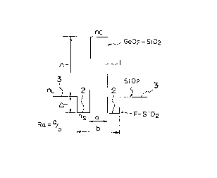
In the W-type profile configuration of the refractive
indexofthedispersioncompensatingoptical fiber, asidecore
2 which has a lower index of refraction than that of a center
corelisdisposedaroundthecentercorelwhichhasthehighest
index of refraction, and a clad 3 which has a lower index of
18
CA 02232101 1998-03-13
refraction than that of the center core 1 but a higher index
of refraction than that of the side core 2 is disposed around
the side core 2. Thus, a d:istribution of the refractive index
is W-type.
The clad 3 is formed by a layer of pure silica (SiO2).
The side core 2 is formed by doping pure silica (SiO2) with
fluorine (F) which lowers an index of refraction. The center
corelis formedby dopingpure silicawithgermanium (Ge) which
increases an index of refraction.
In the configuration of the refractive index shown in
Fig.l,aspecificrefractiveindexdifference A+ofthecenter
core 1 from the clad 3 is defined by the following e~uation
~1), where the index of refraction of the center core 1 is nC,
the index of refraction of the side core 2 is ns, and the index
of refraction of the clad 3 is nL:
A-~ = {(nc2-nL2)/2nC2}XlOO ... (1)
Meanwhile, a specific refractive index difference A-
of the side core 2 from the clad 3 is defined by the following
equation (2):
~ - = {(ns2-nL2)/2ns2}XlOO ~.. (2)
The dispersion compensating optical fiber according to
the preferred embodiment, converting from the conventional
idea of a module of an optical fiber only for compensation of
19
CA 02232101 1998-03-13
dispersion, has such a structure which realizes a function of
compensating dispersion which is created during propagation
through a single-mode optical fiber and a function as a
transmission line for transmitting an optical signal, and
therefore, avalueofdispersionofthedispersioncompensating
opticalfiber is set to be larger than -20ps/nm/ km but smaller
than -10ps/nm/km. Thus, since a value of dispersion of the
dispersion compensating optical fiber according to the
preferred embodiment is a negative dispersion value which is
smaller t:han a dispersion value -55ps/nm/km of a conventional
dispersion compensating optical fiber which is formed as a
module (e.g., a dispersion compensating optical fiber module
according to Japanese Laid-Open- Patent Publication No.
Hei-6-11620), conditions which regulate designing of the
profile of the W-type distribution of the refractive index are
moderate, which allows to Eorm a transmission line having low
non-linearity. A single-mode transmission optical fiber which
has zero dispersion at the wavelength of 1.31 ~ m has a
dispersionslopeofaboutl7ps/nm2/kmatthewavelengthofl.55
~ m but a dispersion slope of about 0.06 ps/nm2/km in the
wavelengl:h band of 1.55 ~ m.
Further, in the preferred embodiment, for reduction and
compensat:ion of dispersion which is created in opticalsignals
CA 02232101 1998-03-13
attherespectivewavelengt:hsofwavelengthdivisionmultiplex
light transmission in the wavelength band of 1.55 ~ m as the
optical signals propagate through the single-mode optical
fiber uni.formly to substantially zero dispersion, a ratio of
the dispersion value to the dispersion slope of the dispersion
compensating optical fiber in the wavelength band of 1.55 ~
m is set to be substantially equal in the absolute value but
with the opposite sign to a ratio of the dispersion value to
the dispersion slope of the single-mode optical fiber in the
same wavelength band of 1.55 ~ m. When the ratio of the
dispersion value to the dispersion slope is set as such, if
the dispersion compensatin.g optical fiber is connected to the
single-mode optical fiber which has zero dispersion at 1.31
~ m above in substantially the same length as the single-mode
optical fiber, it is possible to abridge and compensate
dispersion which is created in the wavelength division
multiple:{ed signals at the respective wavelengths in the
wavelenglh band of 1.55 ~ m as the optical signals propagate
through the single-mode optical fiber uniformly to
substantiallyzerodispers:ion attherearendofthedispersion
compensat:ing optical fiber.
An important requirement of a dispersion compensating
optical fiber is realization of low dispersion in a wide range
CA 02232101 1998-03-13
in the wavelength band of 1.55 ~ m when the dispersion
compensating optical fiber is connected to a single-mode
optical fiber. Hence, the inventor studied a possibility of
increasing a compensation rate of dispersion, in an effort to
optimize the profile of the W-type distribution of the
refractive index. The compensation rate of dispersion is
defined by the following equation (3):
Compensation Rate = {S (DCF)S(SMF)}/{D(DCF)/D(SMF)}... (3)
In the equation (3) above, S(DCF) is an average value
of the dispersion slope of the dispersion compensating optical
fiber in the wavelength band of 1.55 ~ m, S(SMF) is an average
value of a dispersion slope in the wavelength band of 1.55
~ m of a single-mode transmission optical fiber which has zero
dispersi~natthewavelengt:hofl.31 ~ m, D(DCF) is adispersion
value of the dispersion compensating optical fiber at the
wavelength of 1.55 ~ m, and D(SMF) is a dispersion value at
the wavelength of 1.55 ~ m of the single-mode transmission
optical fiber which has zero dispersion at the wavelength of
1.31 ~ m.
It is verified that in the dispersion compensating
optical i-iber which has the W-type profile of the refractive
index, a dispersion slope which compensates low dispersion in
the wave:Length band of 1.55 ~ m is obtained if the ratio R
CA 02232l0l l998-03-l3
A (R A=~-/A+) of the specific refractive index difference
A-ofthesidecore2 from the clad3 to thespecific refractive
index di:Eference ~+ of the center core 1 from the clad 3 is
equal to or smaller than -0.25. Noting this, the value R A of
the dispersion compensating optical fiber according to the
preferre~ embodiment is set to -0.25 or smaller.
Table 1 compares a ~ompensation rate when the value R
~ is -0.285 with compensation rates with changed parameters
for the '~-type profile.
[Table 1
A + A - Core Dispersion Dispersion Compensation
diameter SlopeRate
(%) (%) (~ m) (ps/nm/km) (ps/nmZ/km) (%)
2.8 -0.7982.23 219 -0.78 94
2.4 -0.6842.44 -178 -0.73 108
2.0 -0.5702.86 -99 -0.37 99
1.6 -0.4563.19 -72 -0.29 106
1.2 -0.3423.69 -46 -0.16 92
0.8 -0.2284.02 -18 -0.07 105
The dispersion in Table 1 is actual measurements at the
wavelenglth of 1.55 ~ m, and the dispersion slopes are average
valuesamongthewavelengths froml.53 ~ mtol.57 ~ m.Thedata
shown in Table 1 are data which are obtained when a value of
23
CA 02232101 1998-03-13
the ratio Ra (Ra=a/b) of the diameter a of the center core 1
to the diameter b of the side core 2 is fixed to 0.4.
As understood from Table 1, as the value R ~ is - 0.285,
high compensation rates of dispersion from 92% to 108% are
obtained.
Next, the inventor identified an optimum range of the
value Ra which can sufficiently satisfy a compensation ratio
of dispersion, by simulation under the condition the value R
~ was -0.25 or smaller. Fig. 2 shows the results of the
simulation. The solid line in Fig. 2 is a theoretical curve,
while the plot points represent the data which were obtained
by the simulation.
It is verified from the simulation results shown in Fig.
2 that sufficiently satisfactory high compensation rates are
obtained if the value Ra is in the range from 0.3 to 0.4. Based
on the simulation results, the value Ra of the dispersion
compensating optical fiber according to the preferred
embodiment is set to a value in the range from 0.3 to 0.4.
Further, the simulation results have also identified
that when the value Ra is set to be within the range from 0.3
to 0.4 and the value R ~ is set to be -0.25 or smaller, a value
of the specific refractive index difference ~+ of the center
core 1 from the clad 3 must be 1.8% at maximum or smaller than
24
CA 02232101 1998-03-13
the same to allow the dispersion value to be larger than - 20
ps / nm / km but smaller than - 10 ps / nm / km. When the value
~+ is 1.8% or smaller, it is possible to enlarge the mode field
diameter (MFD) of the dispersion compensating optical fiber.
In the preferred embodiment, the mode field diameter is
enlarged to 6 ~ m or larger. Comparing to the value 4.4 ~ m of
themode field diameter of the dispersion compensating optical
fiber module according to Japanese Laid-Open Patent
Publication No. Hei-6-11620, it is clear that the value of the
mode fie:Ld diameter which is 6 ~ m or larger is sufficiently
large. IE the value ~+ is too small, during fabrication of
the dispersion compensating optical fiber, the layer of
fluorine (F) which is doped in the side core 2 becomes unstable
and the clear W-type profile configuration shown in Fig. 1 can
notbeachieved.Topreventthis, itisnecessarythatthevalue
~+ is 1.0% or larger. In the preferred embodiment, the value
~+ is set to be 1.0% or larger but 1.8% or smaller.
That is, the dispersion compensating optical fiber
module according to the present invention has the W-type
profile of the distribution of the refractive index, and the
specific refractive index difference A+ of the center core
1 from the clad 3 is set to be from 1.0% to 1.8%, the value
R A (R A=A-/A+) is set to -0.25 or smaller, and the value Ra
CA 02232101 1998-03-13
is set to be from 0.3 to 0.4, so that the mode field diameter
is 6 ~ m or larger, and a value of dispersion in the wavelength
band of 1.55 ~ m is from -20ps/nm/km to -lOps/nm/km.
In the conventional dispersion compensating optical
fiber which is formed as a module, since a negative high-
dispersion value and a high-dispersion slope are pursued for
compensation, in a short fiber length, of dispersion which
propagates through a single-mode optical fiber, the specific
refractive index difference ~+ of the center core of the
dispersion compensating optical fiber which has the W-type
profile is as large as and close to 2%. Thus, a non-linearity
occurs as the specific refractive index difference ~+ of the
centercorebecomesalargevalue, andthetransmissioncluality
may be lowered by a waveform distortion resulting from the
non-line~rity, and the transmission loos due to bending may
beincrea.sed.Inaddition, despitecircumstanceswhichrec~uire
to decrease the core diameter, since the mode field diameter
of the conventional dispersion compensating optical fiber
module is at most about 5 ~ m even when enlarged, and such a
structure is obtained, where the mode field diameter is small.
Since the specific refractive index difference of the center
core is t:oo large, the transmission c~uality is lowered due
to non-linearity, and a transmission loss due to bending is
CA 02232101 1998-03-13
large. In contrast, the dispersion compensating optical fiber
accordingtotheembodimenthasalownegative dispersionvalue
and a low dispersion slope, and therefore, conditions which
regulate designing of parameters which define the W-type
profilearemoderate.Thisallowstoobtainalownon-linearity,
and such a structure can be obtained where the mode field
diameter is large. Thereby, it is possible to decrease the
specific refractive index difference ~+ of the center core
to 1.8% or less, and it is possible to suppress a lowering
of the lransmission c~ality, which results from the non-
linearity of a dispersion compensating optical fiber, and
possible to suppress an inc:rease of the transmission loss due
to bending of the dispersion compensating optical fiber.
An experiment which was conducted by the inventor has
verified that it is possible to sufficiently achieve the
condition that the mode field diameter is 6 ~ m or larger at
the wavelength of 1.55 ~ m while keeping a transmission loss
due to bending to 5dB/m or smaller where the diameter is 20mm.
Thisvaluesufficientlysatisfiestheconditionsforanoptimum
transmission optical fiber which has low non-linearity,
sufficie:ntly deals with bending as a light transmission line,
andis most appropriate to wavelength division multiplex light
transmission.
CA 02232101 1998-03-13
Fig. 5 shows a wavelength division multiplex light
transmission line according to the preferred embodiment. The
light transmission line is obtained by connecting the
dispersion compensating optical fiber DCF according to the
preferre~d embodiment to a single-mode transmission optical
fiber SMF which has zero dispersion at the wavelength of 1.31
,u m, where the dispersion compensating optical fiber DCF has
substantially the same length as the single-mode transmission
optical fiber SMF. In Fig. 5, denoted at 4 is a light amplifier
whose gain bandwidth is in the wavelength band of 1.55 ,u m,
while de:noted at 5 is a receiving station.
Table 2 shows the results whether the wavelength division
multiplex light transmission line is suitable as various types
of transmission lines.
[Table 2]
FiberSMF DSF SMF+WDFCF SMF+WDFCF DFF SMF+DFCF For
Transmission
- hine
WDM
transport-- X A A O
ation
In Table 2, the symbol X indicates that the line is not
appropriate as a wavelength division multiplex light
transmission line, the symbol ~ indicates the line is not
preferab].e very much although the line has practicability, the
28
CA 02232101 1998-03-13
symbol O indicatesthelineisalinewhichissomewhatbetter,
andthesymbol ~ indicates the]ineis aline whichissuitable
as a wavelength division multiplex light transmission line.
The transmission line according to the preferred embodiment
with three ~ is an optimum line for wavelength division
multiplex light transmission.
The optical fiber SMF shown in Table 2 is the installed
single-mode optical fibers which have zero dispersion at the
wavelength of 1.31 ~ m. The optical fiber DSF is a dispersion
shifting optical fiber which has zero dispersion at the
wavelength of 1.55 ~ m. The optical fiber SMF+MDCF is a line
which is obtained by connecting a dispersion compensating
optical fiber module whose distribution of refractive index
is of the matched type to a single-mode transmission optical
fiber wh:ich has zero dispersion at the wavelength of 1.31 ~
m. The optical fiber SMF+WDFCF is an optical line which is
obtained by connecting a single-mode transmission optical
fiber to a dispersion compensating optical fiber module whose
distribution of refractive index has a W-type profile. The
optical fiber DFF is a dispersion flat fiber which has zero
dispersion at the wavelength of 1.55 y m and whose dispersion
slope in that waveband is zero. The optical fiber SMF+DFCF For
Transmission Line is the light transmission line according to
29
CA 02232101 1998-03-13
the preferred embodiment, which is a line which is obtained
by connecting the dispersion compensating optical fiber
according to the preferred embodiment to a single-mode
transmission optical fiber which has zero dispersion at the
wavelength of 1.31 ~ m in such a manner that the dispersion
compensating optical fiber has substantially the same length
as the single-mode transmission optical fiber.
While the results shown in Table 2 indicate that the
dispersion flat fiber DFF as well is a light transmission line
which is suitable for wavelength division multiplex light
transmission, this type of dispersion flat fiber accompanies
strictconditionsregardingadistributionofrefractiveindex.
Sincecharacteristicssuchasdispersionandadispersionslope
are changed even with the slightest deviation from the
conditions, it is difficult to fabricate this type of
dispersionflatfiber.Thus, this typeofdispersionflatfiber
is not necessarily desirable as a stable general-purpose
wavelength division multiplex light transmission line. It is
verified that the light transmission line according to the
preferred embodiment is an optimum general-purpose optical
line. The light transmission line according to the preferred
embodimentisexpectedasthemostsuitablewavelengthdivision
multiplex light transmission line of the next generation.
CA 02232101 1998-03-13
Next, specific examples of the present invention will
bedescribed.First, as anexamplel, adispersioncompensating
optical ~iber was formed as a W-type which had a distribution
of refractive index as that shown in Fig. 1, ~+ of 1.44%, R
~ of -0.285 and Ra of 0.37. Fig. 3 shows results on wavelength
dispersion characteristics of the dispersion compensating
optical fiber of the example 1.
In a similar manner, a dispersion compensating optical
fiberwasformedasanexample2 whichhadaW-type distribution
ofrefractiveindex, A+ofl.11%, R A of-0.375 andRaofO.33.
Fig. 3 also shows results on wavelength dispersion
characteristics of the dispersion compensating optical fiber
oftheexample2.Fig.3 furthershows, asacomparisonexample,
data which are obtained by multiplying wavelength dispersion
characteristics of a single-mode optical fiber which has zero
dispersion at the wavelength of 1.31 ~ m (i.e., SMF data) by
-1 .
As clear from the wavelength dispersion characteristics
shown in Fig. 3, the data for the example 1 and the data for
the example 2 are both close to the data which are obtained
by multiplying the wavelength dispersion characteristics of
the sing]e-mode optical fiber by -1. This indicates that if
the compensating optical fibers of the examples 1 and 2 are
CA 02232101 1998-03-13
connected to the single-mode optical fiber in such a manner
that the dispersion compensating optical fibers have
substantially the same length as the single-mode transmission
optical fiber, it is possible to abridge and compensate
dispersion which is created the respective wavelengths in the
wavelength band of 1.55 ~ m during propagation through the
single-mode transmission optical fiber effectively to
substantiallyzerodispersionatthe rearendofthedispersion
compensating optical fiber.
Next, Table 3 compares the results on characteristics
of a dispersion compensating optical fiber according to other
example of the present invention with characteristics of
conventional dispersion compensating optical fiber modules.
In Table 3, the letter W indicates that a distribution of
refractive index has a W--type profile, while the letter M
indicates that a distribution of refractive index is of the
matched type. Further, the dispersion values in Table 3 are
values at: the wavelength of 1.55 ~ m, bending losses indicate
transmis.sion losses due to bending with a diameter of 20mm,
and the symbol MFD indicates mode field diameters.
CA 02232l0l l998-03-l3
[Table 3]
Dispersion Bending
Type Dispersion Slope Loss With MFD
(ps/nm/km) (ps/nm2/km) ~ = 20 (~ m)
(dB/m)
Example
W -15,55 -0.0561 3.136 7.83
Module W-106.78 -0.3643 8,183 5.06
Module M -80.51 0.0213 5.269 4.09
With respect to the dispersion compensating optical
fiber according to the example shown in Table 3, dispersion
indicates a negative value which is as low as - 15.55ps/nm/km,
and the dispersion slope has a negative value which is as small
as -0.0561ps/nm2/km. Thus, compared with the conventional
dispersion compensating optical fiber modules, the dispersion
compensating optical fiber has sufficiently small negative
dispersion and a sufficiently small negative dispersion slope.
In additi.on, such a fiber structure can be obtained, where the
bending loss is small since the mode field diameter is 7.83
f~ mwhich is magnificently larger than that of the conventional
dispersion compensating optical fiber modules, and an increase
of the specific refractive index difference of the center core
can be suppressed. Hence, the bending loss becomes a small
value and.a lowering of the transmission c~uality resulting from
non-linearity can be suppressed. Therefore, it has been
verified that this optical transmission line is most suitable
CA 02232101 1998-03-13
for a high-speed large capacity wavelength multiplex .
transmisslon .
34