Note : Les descriptions sont présentées dans la langue officielle dans laquelle elles ont été soumises.
CA 02232881 1998-03-20
TITLE OF THE INVENTION:
TWO-CYCLE INTERNAL COMBUSTION ENGINE
FIELD OF THE INVENTION
The present inventio:n relates to a two-cycle internal
combustion engine capable of giving directivity to injection of an air-fuel
mixture into a combustion chamber for preventing blowby of the air-fuel
mixture, thereby enhancing a fue]L consumption and an exhaust gas
purifying performance.
lS BACKGROUND OF THE INVENTION
In a related art two-cycle internal combustion engine, fuel
supplied from a carburetor or the like is mixed with intake air, and the air-
fuel mixture is sucked in a crank chamber and then supplied in a
combustion chamber through scavenging openings. In this engine, since
an opening timing of an exhaust opening is set to be earlier than an
opening timing of the scavenging openings (an upper edge of the exhaust
opening is higher than upper edges of the scavenging openings), there
may easily occur exhaust of the air-fuel mixture supplied in the
combustion engine into the exhaust opening, that is, a so-called "blowby"
of the air-fuel mixture.
The blowby phenome:non is suppressed by an exhaust-
pulsation effect; however, it is difficult to suppress the blowby over the
entire operational range. As a result, the blowby exerts adverse effect on a
fuel consumption and an exhaust gas purifying performance.
Two-cycle internal connbustion engines intended to solve
such an inconvenience have been disclosed in Japanese Patent Laid-open
Nos. Hei 3-100318 and Hei 5-302521.
In the two-cycle internal combustion engine described in
Japanese Patent Laid-open No. Hei 3-100318, a high pressure chamber is
connected to a crank chamber through a check valve; the high pressure
CA 02232881 1998-03-20
'2
chamber is connected to a combustion chamber through an air passage;
and a solenoid valve is interposed at a lower end of the air passage and a
fuel injection valve for injecting luel in the combustion chamber is
provided at an upper end of the air passage.
s
In the two-cycle internal combustion engine described in
Japanese Patent Laid-open No. Hei 5-302521, a chamber portion is disposed
adjacently to a crank case and a cylinder block; an intake control valve is
interposed between a crank charnber and the chamber portion; a
10 scavenging control valve is interposed between the chamber portion and a
combustion chamber in a cylinder; and a fuel injection valve for injecting
fuel in the chamber portion is provided.
The two-cycle internal combustion engine described in
lS Japanese Patent Laid-open No. Hei 3-100318 has a problem. Since a fuel
supply opening is provided in a side wall of the cylinder at a position
facing to the combustion chamber and the fuel injection valve is disposed
directly perpendicularly to the fuel supply opening, sprayed fuel collides
with the cylinder wall on the exhaust opening side which is opposed to the
20 fuel supply opening and thereby the sprayed fuel is liable to adhere on the
cylinder wall.
When a fuel spraying timing is set to be earlier in order to
prevent interference between the pislon and the sprayed fuel, the sprayed
25 fuel tends to be blown-by in the exhLaust opening; while the fuel supply
opening is disposed at a higher position to delay the fuel spraying timing,
the fuel injection valve is directly exposed to a combustion gas at a high
temperature, causing an inconvenience that the injection valve needs a
high thermal resistance.
Further, in the two-cycle internal combustion engine
described in Japanese Patent Laid-open No. Hei 5-302521, since an air-fuel
mixture injected from the scavenging control valve is supplied into the
combustion chamber through all of the scavenging openings, the blowby
35 of the air-fuel mixture from the exhaust opening cannot be avoided.
In the two-cycle internal combustion engine of a type in
which fuel is directly injected into a cylinder, the directivity of sprayed fuelis generally very important. This is because, if the directivity is degraded,
CA 02232881 1998-03-20
~3
there occur short-cut of sprayed fue] through an exhaust opening and/or
interference with a cylinder wall, combustion chamber wall, piston and
the like during diffusion of sprayed fuel.
If there occurs the above interference at a stage in which
atomization and diffusion of sprayed fuel are insufficient, fuel tends to
adhere on the walls. As a result, the fuel is difficult to be converted into
an air-fuel mixture. This obstructs combustion and degrades the engine
efficiency. In this regard, the related art engine has failed to examine
directivity of sprayed fuel into a combustion chamber.
In particular, for a roti~ry valve type fuel injection control
valve in which a valve opening is extended in the peripheral direction, it
is difficult to usually inject fuel in the controlled direction during fuel
inj ection .
SUMMARY OF THE INVENTION
The present invention relates to an improved two-cycle
internal combustion engine intended to solve the above-described
problems, and according to an invention described in claim 1, there is
provided a two-cycle internal combustion engine in which a control valve
is disposed, in a communicating passage for communicating a combustion
chamber to a chamber portion adjacent to the combustion chamber, for
controlling opening/closing the communicating passage, and a fuel or an
air-fuel mixture is supplied in the combustion chamber through the
communicating passage, characterized in that a portion of the
communicating passage between the control valve and a fuel or air-fuel
mixture supply opening facing to thLe combustion chamber is configured
that sprayed fuel is injected from the control valve to part or all of a wall
surface of the communicating passage portion; and the wall surface of the
communicating passage portion is formed in such a manner as to be
directed toward the combustion chamber side as seen in the direction from
the control valve to the fuel supply opening in order to serve as a guide
for controlling directivity of the spray fuel.
According to the invention described in claim 1, which is so
configured as described above, the communicating passage portion
between the control valve and the fuel supply opening has a guide
CA 02232881 1998-03-20
function for controlling directivity of sprayed fuel. Accordingly, during
injection of a rich air-fuel mixture, the directivity of sprayed fuel is usuallycontrolled at optimum by the guide. As a result, it is possible to prevent
occurrence of short-cut (blowby) of sprayed fuel through the exhaust
5 opening and/or interference with t]-e cylinder wall surface, combustion
chamber wall, piston and the like, and hence to achieve a high level fuel
consumption and a high exhaust gas purifying performance.
According to a configuration of an invention described in
10 claim 2, in addition to the configuration of the invention described in
claim 1, an upper space from the injected fuel port is extended and thereby
a negative pressure in the upper space caused by the fuel injection is
reduced. As a result, even in the case where the communicating passage
portion is relatively short, the negative pressure in the upper space from
15 the injected fuel port can be close to a negative pressure in a lower space
from the injected fuel port. Thus, it is possible to easily keep the vector of
the guiding direction for the fuel injected and sprayed, and hence to
desirably prevent interference of the sprayed fuel with the cylinder wall,
combustion chamber wall, piston ancl the like.
According to a configuration of an invention described in
claim 3, in addition to the configuration of the invention described in
claim 2, the upper space from the injected fuel port becomes sufficiently
large. As a result, a negative pressure in the upper space caused by fuel
25 injection can be sufficiently reduced, and even in the case where the
communicating passage portion is rlelatively short, the negative pressure
in the upper space from the injectecl fuel port can be close to a negative
pressure in a lower space from the injected fuel port, so that it is possible tomore easily keep the vector of the guiding direction for the fuel injected
30 and sprayed, and hence to desirably prevent interference of the sprayed
fuel with the cylinder wall, combustion chamber wall, piston and the like.
BRIEF DESCRIPTION OF THE DRAWINGS
Fig. 1 A schematic vertical sectional view of a two-cycle
internal combustion engine in a first embodiment (Embodiment 1) of an
invention described in claim 1.
CA 02232881 1998-03-20
I_
Fig. 2 A schematic enlarged view of an essential portion
shown in Fig. 1.
Fig. 3 A diagram illustrating an operational cycle of the two-
5 cycle internal combustion engine in the embodiment shown in Fig. 1.
Fig. 4 A schematic enlarged view, similar to Fig. 2, showing
an essential portion of a two-cycle internal combustion engine in a second
embodiment (Embodiment 2) of the iinvention described in claim 1.
Fig. 5 A schematic enlarged view, similar to Fig. 2, showing
an essential portion of a two-cycle internal combustion engine in one
embodiment (Embodiment 3) of an invention described claims 2 and 3.
Fig. 6 A transverse sectional side view taken on line VI-VI of
Fig. 5, showing a recessed portion and a rich air-fuel mixture supply
opening portion.
Fig. 7 A front view, seen from the direction A of Fig. 5,
20 showing the recessed portion and the rich air-fuel mixture supply opening
portion.
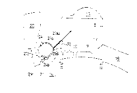
Fig. 8 A view illustrating the background of the embodiment
shown in Fig. 5.
DETAILED DESCRIPTION OF THE PREFERRED EMBODIMENTS
Hereinafter, a first embodiment (Embodiment 1) of an
invention described in claim 1 will be first described with reference to Figs.
30 lto3.
Fig. 1 is a vertical sectional side view of a spark ignition type
two-cycle internal combustion engi ne in this embodiment; Fig. 2 is a
schematic enlarged view of an essential portion shown in Fig. 1; and Fig. 3
35 is a diagram illustrating an operational cycle of the internal combustion
engine shown in Fig. 1. In these figures, a spark ignition type two-cycle
internal combustion engine 1 is mowlted on a motorcycle (not shown). In
this engine 1, a cylinder block 3 and a cylinder head 4 are sequentially
superimposed on the crank case 2 and integrated to each other.
CA 02232881 1998-03-20
A piston 6 is vertically slidably inserted in a cylinder bore 5
formed in the cylinder block 3. The piston 6 is connected to a crank shaft 8
by means of a connecting rod 7, so that the crank shaft 8 is rotated by
5 vertical movement of the piston 6.
An intake passage 10 extending forward from a rear side of a
vehicular body is connected to an intake passage 10 in the crank case 2. A
throttle valve (not shown) and a reed valve 12 are interposed in series in
lO the intake passage 10. The throttle valve is connected to a throttle grip
(not shown) through a connecting nneans (not shown) in such a manner
that an opening degree of the throttle valve is increased when the throttle
grip is twisted in one direction.
In the crank case 2 ancl the cylinder block 3 are formed air
supply scavenging passages 14 of five pieces in total: four pieces (two pieces
disposed on each of right and left sicles) of air supply scavenging passages
for communicating an upper portion of the cylinder bore 5 to the crank
case 9; and a rear side air supply scavenging passage (which will be
20 described later) opened under both an air-fuel mixture supply opening
(fuel supply opening) 22 and a high:ly compressed gas intake opening 27.
Ends of these scavenging passages on the cylinder bore 5 side form
openings 15 opened to the cylinder bore 5. The latter air supply scavenging
passage 14 is directly connected to the intake passage 10 in the crank case 2
25 on the downstream side of the reed valve 12.
An exhaust opening 17 of an exhaust passage 16 on the
cylinder bore 5 side extends higher th.an the openings 15 of these air supply
scavenging passages 14, and is disposed at a position opposed to the rich
30 air-fuel mixture supply opening (fuel supply opening) 22 (which will be
described later). Reference numeral 18 indicates an exhaust control valve,
provided near the exhaust opening 17 of the exhaust passage 16, for
changing a height of an upper edge of the exhaust opening 17 so as to vary
an exhaust timing and also changing a cross-section of the exhaust passage
35 16.
A combustion chamber 13 formed in an approximately semi-
spherical shape, which is disposed over the cylinder bore 5, is offset toward
CA 02232881 1998-03-20
the exhaust opening 17. An ignition plug 19 is disposed to the combustion
chamber 13.
A chamber portion 20 is juxtaposed to the cylinder block 3
S disposed sideward of the combustion chamber 13 in such a manner as to be
offset toward the rear side of the body. A valve containing hole 23 is
disposed halfway of a communicaling passage for communicating the
chamber portion 20 to the combustion chamber 13, and a rich air-fuel
mixture injection control valve 24 composed of a rotary valve is rotatably
l O inserted in the valve containing hole 23. The rich air-fuel mixture
injection control valve 24 is rotated at the same rotational speed as that of
the crank shaft 8 in the direction reversed to the rotational direction of the
crank shaft 8 (clockwise in Fig. 1) by a transmission mechanism 25.
An injection port of a fuel injection device 26 is disposed in
such a manner as to face to a portion 21b, of the communicating passage
21, located on the upstream side of t:he position at which the rotary valve
24 is disposed.
A highly compressed gas for forming a rich air-fuel mixture is
supplied into the chamber portion 20 from the highly compressed gas
intake opening 27 formed in a cylinder side wall at a position facing to the
combustion chamber 13.
The highly compressed gas is supplied into the chamber
portion 20 through the communicating passage 28 for communicating the
chamber portion 20 to the highly cornpressed gas intake opening 27 while
being controlled by a rotary valve axially integrated with the rich air-fuel
mixture injection control valve 24.
The highly compressed gas supplied into the chamber portion
20 flows in the communicating passage portion 21b, and is mixed with fuel
injected from the fuel injection device 26 in a mixing chamber 21c formed
in the course of the communicating passage portion 21b, to form a rich air-
fuel mixture. When the rich air-fue]L mixture injection control valve 24 is
opened, the rich air-fuel mixture t hus formed is press-fed by a high
pressure in the chamber portion 20, and is injected from the rich air-fuel
supply opening 22 into the combustion chamber 13 through a
CA 02232881 1998-03-20
communicating passage portion 21a on the downstream side from the rich
air-fuel mixture injection control valve 24.
Here, the positional relationship of the communicating
5 passage portion 21a on the downstream side from the rich air-fuel mixture
control valve 24 to the rich air-fuel rnixture injecting control valve 24 and
the rich air-fuel supply opening 22 is set such that an upper wall surface
21au of the communicating passage portion 21a serves as a guide for
allowing sprayed fuel injected frorn the rich air-fuel mixture injection
10 control valve 24 to be directed toward the combustion chamber 13. To be
more specific, the upper wall surface 21au of the communicating passage
portion 21a, which serves as the guide, is formed in such a shape as to be
directed on the combustion chamber 13 side as seen in the direction from
the rich air-fuel mixture injection control valve 24 to the rich air-fuel
15 mixture supply opening 22.
A rich air-fuel mixture flows as follows. When a leading end
of a peripheral cutout 24a of the rich air-fuel mixture injection control
valve 24 rotating counterclockwise passes over a lower wall surface 21al of
20 the communicating passage portion 21a, the rich air-fuel mixture in the
mixing chamber 21c is injected in the communicating passage portion 21a.
Since the direction along which the rich air-fuel mixture is injected
substantially corresponds to the rotational direction of the rich air-fuel
mixture injection control valve 24, the rich air-fuel collides with the
25 deepest portion of the upper wall surface 21au on the opposed side to the
rotational direction of the rich air-fuel mixture injection control valve 24
to be changed in its course, and advances toward the rich air-fuel mixture
supply opening 22 while being guided by the upper wall surface 21au.
Finally, the rich air-fuel mixture outgoing from the opening 22 is diffused
30 and sprayed toward the combustion chamber 13 while being kept in its
guided course.
The spark ignition type two-cycle internal combustion engine
1, shown in the figures, having the above configuration is operated as
35 follows: When the crank shaft 8 is rc)tated counterclockwise in Fig. 1 by a
starter motor (not shown), the exhau,t opening 17 is blocked by the piston
6 at a point of 90AKbefore a top deacl center (TDC) (compression stroke) as
shown in Fig. 3. At this time, the rich air-fuel mixture injection control
valve 24 as the rotary valve is opened, and a highly compressed gas in the
CA 02232881 1998-03-20
combustion chamber 13 flows in the chamber portion 20 through the rich
air-fuel mixture forming highly compressed gas intake opening 27 and the
communication passage 28.
S Then, at a point of about 75AKbefore the top dead center(TDC), the rich air-fuel mixture supply opening 22 at the end portion of
the communication passage 21 on the combustion chamber 13 side is
blocked by the piston 6 and then the rich air-fuel mixture forming highly
compressed gas intake opening 27 is blocked by the piston 6, so that the
supply of the rich air-fuel mixture into the combustion chamber 13 and
the charging of the highly compressed gas into the chamber portion 20 are
sequentially completed.
The interior of the c ombustion chamber 13 is further
compressed, and at a point before the top dead center, the ignition plug 19
is ignited. Beside, the crank chamber 9 is continuously expanded by
upward movement of the piston 6, to thus continue the intake operation.
After the piston 6 reaches the top dead center (TDC), the air-
fuel mixture in the combustion charnber 13 is burned and the interior of
the combustion chamber 13 is expa:nded. Then, the crank chamber 9 is
compressed by downward movement of the piston 6 to compress air in the
crank chamber 9.
At a point of 90AKafter the top dead center (TDC) (which
varies depending on the vertical position of the exhaust control valve 18),
the exhaust opening 17 is opened to exhaust a combustion gas from the
exhaust passage 16.
Further, at a point of about 122AKafter the top dead center
(TDC), the scavenging openings 15 are opened by downward movement of
the piston 6. As a result, the air (not containing fuel) compressed in the
crank chamber 9 flows from the scavenging openings 15 into the
combustion chamber 13 through the air supply scavenging passages 14 to
push the burnt gas in the combustion chamber 13 toward the exhaust
opening 17. Thus, scavenging only by the air is performed. At the same
time, fuel is injected from the fuel injection device 26 into the mixing
chamber 21c to create a rich air-fuel nnixture.
CA 02232881 1998-03-20
Next, at a point of about 58AKafter a bottom dead center
(BDC), the scavenging openings 15 are blocked by upward movement of
the piston 6, and the scavenging due to flow-in of the air from the
scavenging openings 15 is stopped. And, substantially from this point, the
5 rich air-fuel mixture injection control valve 24 opens the communicating
passage 21, and the air-fuel mixture in the mixing chamber 21c passes
through the communication passage portion 21b, rich air-fuel mixture
injection control valve 24 and comm.unication passage portion 21a and is
injected from the rich air-fuel supply opening 22 into the combustion
lO chamber 13. At the same time, air is sucked in the crank chamber 9 from
the intake passage 10 through the reed valve 12 by expansion of the
interior of the crank chamber 9 by upward movement of the piston 6. In
addition, upon injection of the above rich air-fuel mixture, there little
occurs blowby of the air-fuel mixture
In this way, in the spark ignition type two-cycle internal
combustion engine 1, since scavenging only by air is performed at the
beginning of the scavenging step, it is possible to prevent a blowby
phenomenon in which an air-fuel mixture passes through the interior of
20 the combustion chamber 13 and is exhausted in the exhaust passage 16,
and hence to improve a fuel consurnption and prevent air pollution due
to an unburnt gas.
Since an air-fuel mixture produced by mixing air charged in
25 the chamber portion 20 with fuel injected from the fuel injection device 26
in the mixing chamber 21c is rich and the rich air-fuel mixture flows in the
combustion chamber 13 which has been sufficiently scavenged by air (not
containing fuel) having passed through the air supply scavenging passages
14, the rich air-fuel mixture becomes an air-fuel mixture at a suitable
30 concentration in the combustion chamber 13. The air-fuel mixture thus
adjusted in the combustion chamber 13 allows desired combustion, thus
attaining a high level fuel consumption and a high exhaust gas purifying
performance.
The positional relationship of the communicating passage
portion 21a on the downstream side from the rich air-fuel mixture
injection control valve 24 to the rich air-fuel mixture injection control
valve 24 and the rich air-fuel mixture supply opening 22 is set such that
the upper wall surface 21au serves as the guide for allowing sprayed fuel
CA 02232881 1998-03-20
11
injected from the rich air-fuel mixture injection control valve 24 to be
directed toward the combustion chan:lber 13. The upper wall surface 21au
of the communicating passage portion 21a, which serves as the guide, is
formed in such a shape as to be directed toward the combustion chamber
5 13 side as seen in the direction from the rich air-fuel mixture injection
control valve 24 to the rich air-fuel mixture supply opening 22. As a
result, during injection of a rich air-fuel mixture, the directivity of sprayed
fuel is usually controlled at optimum by the guide, so that it is possible to
prevent occurrence of short-cut (blowby) of sprayed fuel from the exhaust
10 opening 17, and interference with t]le cylinder wall surface, combustion
chamber wall, piston 6 and the like, and hence to achieve a high level fuel
consumption and a high exhaust gas purifying performance.
Next, a second embodiment (Embodiment 2) of the invention
15 described in claim 1 will be described with reference to Fig. 4.
In this embodiment, the rich air-fuel mixture injection
control valve 24 is configured to be rotated at the same rotational speed as
that of the crank shaft 8 in the direction (clockwise in Fig. 1) opposed to the
20 rotational direction of the crank shaft 8. Accordingly, the portion serving
as the guide for allowing sprayed fuel injected from the rich air-fuel
mixture injection control valve 24 to be directed toward the combustion
chamber 13 is the lower wall surfacle 21al of the communicating passage
portion 21a. This point is different from that in Embodiment 1 and other
25 configuration is the same as that i]l Embodiment 1, and therefore, the
detailed description thereof is omitted.
In this embodiment, the same function and effect as those in
Embodiment 1 can be obtained.
Next, one embodiment (Embodiment 3) of an invention
described in claims 2 and 3 will be described with reference to Figs. 5 to 7.
First, the background of this embodiment will be described.
35 With respect to the guide wall of the communicating passage portion 21a
for allowing sprayed fuel injected from the rich air-fuel mixture injection
control valve 24 to be directed toward the combustion chamber 13, the
longer the guide wall, the higher the control effect thereof. On the
contrary, the longer guide wall obstructs the compactness of the internal
CA 02232881 1998-03-20
12
combustion engine, and increases a time required for carrying an air-fuel
mixture to cause a difference in time between the valve opening timing of
the rich air-fuel mixture injection control valve 24 and the injecting
timing of fuel into the cylinder, thereby making it difficult to make
S suitable the valve opening timing in a wide rotational range. Further, the
amount of air for carrying an air-fuel mixture is excessively increased in
proportional to an increment of the length of the communicating passage
portion 21a.
Accordingly, the communicating passage portion 21a is
desired to be as short as possible. However, when the communicating
passage portion 21a is excessively short, the directivity of sprayed fuel
toward the combustion chamber 13 is degraded, leading to interference
with a wall surface of the cylinder 5. The reason for this will be described
lS with reference to Fig. 8.
The air-fuel mixture in;jected from the rich air-fuel mixture
supply opening 22 advances forward while entrapping air in the
surroundings, and is diffused and sprayed. Accordingly, a pressure of a
20 portion around sprayed fuel becomes negative, and a counterclockwise
swirl and a clockwise swirl occur on t:he upper and lower sides of the spray
fuel in Fig. 8, respectively. The stream of sprayed fuel at the time directly
after injection, which is thin and injected at a high speed, strongly entraps
air around the sprayed fuel and thereby the negative pressure around the
25 sprayed fuel becomes higher. In the case of where the sprayed fuel is
injected obliquely upward, the upper space from the injected fuel port is
smaller than the lower space, and thereby the negative pressure in the
upper space becomes particularly hig]ller. As a result, an upward deflecting
force is exerted on the sprayed fuel.
In this embodiment, particularly, in the case where the
communicating passage portion 21a is short, in order to solve a higher
negative pressure in the upper space from the injected fuel port, a recessed
portion 29 is formed in a portion o~F the cylinder side wall at a position
35 higher than the air-fuel mixture supply opening 22 in such a manner that
a recessed surface 29a of the recessed portion 29 is continuous to an edge,
on the rich air-fuel mixture supply opening 22 side, of the upper wall
surface 21au of the communicating passage portion 21a as the guide for
controlling the directivity of sprayed fuel.
CA 02232881 1998-03-20
The recessed portion 2'3 and the upper wall surface 21au of
the communicating passage portion 21a are formed into such shapes in
cross-section taken along a plane p,assing through the center line of the
S cylinder bore 5 that the upper wal]l surface 21au of the communicating
passage portion 21a forms a ski jump as seen in the injecting direction of
the air-fuel mixture (see Fig. 5).
Accordingly, the recessed surface 29a of the recessed portion
lO 29 has two surface portions which are substantially perpendicular to each
other such that one surface portion is substantially perpendicular to the
upper wall surface 21au and the other surface portion is substantially
parallel to the upper wall surface 21au. In addition, a corner portion of the
two perpendicular surface portions is relatively largely rounded.
The corner portion at which the edge of the upper wall
surface 21au on the rich air-fuel mixture supply opening 22 side is
connected to the recessed surface 29a of the recessed portion 29 is liable to
be cutoff and worn by reciprocatingly sliding motion of the piston. In
20 order to avoid the wear, the corner portion is formed in such a manner as
to be set below from the wall surface of the cylinder bore 5 and to be
rounded. With this configuration, it is possible to prevent the wall surface
of the cylinder bore 5 from being damaged by abrasives of the corner
portion.
Figs. 6 and 7 show a transverse sectional view taken in the
peripheral direction and a front view, showing the recessed portion 29 and
the rich air-fuel mixture supply opening 22 portion, respectively. In the
development, the rich air-fuel mixhlre supply opening 22 is formed into
30 an approximately rectangular shape elongated in the peripheral direction,
and the recessed portion 29 is also formed, in a front view, into an
approximately rectangular shape elo]lgated in the peripheral direction and
having the same peripheral length as that of the rich air-fuel mixture
supply opening 22.
The other configurati on is not different from that of
Embodiment 1, and therefore, the detailed explanation is omitted.
CA 02232881 1998-03-20
~4
With this embodiment having the above configuration, the
upper space from the injected fuel port is extended and thereby the
negative pressure in the upper space caused by the fuel injection is
reduced. As a result, even in the calse where the communicating passage
5 portion 21a is relatively short, the negative pressure in the upper space
from the injected fuel port can be ,close to the negative pressure in the
lower space from the injected fuel port, so that it is possible to easily keep
the vector of the guiding direction for the air-fuel mixture injected and
sprayed, and hence to desirably prevent interference of the sprayed fuel
lO with the cylinder wall, combustion chamber wall, piston 6 and the like.
Further, since the recessed portion 29 and the upper wall
surface 21au of the communicating passage portion 21a are formed into
such shapes in cross-section that the upper wall surface 21au forms a ski
15 jump, a sufficient space can be ensured in the upper space from the
injected fuel port. As a result, the negative pressure in the upper space
caused by fuel injection can be sufficiently reduced, and even in the case
where the communicating passage portion 21a is relatively short, the
negative pressure in the upper space from the injected fuel port can be
20 close to the negative pressure in thLe lower space from the injected fuel
port. Thus, it is possible to easily keep the vector of the guiding direction
for the air-fuel mixture injected and sprayed, and hence to desirably
prevent interference of the spra yed fuel with the cylinder wall,
combustion chamber wall, piston and the like.
In each of Embodiments 1 to 3, air for forming an air-fuel
mixture is taken from the rich air-fuel mixture forming highly-
compressed gas intake port 27 formed facing to the combustion chamber
13; however, it may be taken from the crank chamber 9. Even in this case,
30 the same effect as that in each of Embodiments can be obtained by applying
the present invention to the rich air-fuel mixture supply opening (fuel
supply opening) 22.
CA 02232881 1998-03-20
~5
EXPLANATION OF CHARACTERS
1: spark ignition type two-cycle internal combustion engine, 2:
5 crank case, 3: cylinder block, 4: cylinder head, 5: cylinder bore, 6: piston,
7: connecting rod, 8: crank shaft, 9: crank chamber, 10: intake passage, 12:
reed valve, 13: combustion chamber, 14: air supply scavenging passage, 15:
scavenging opening, 16: exhaust passage, 17: exhaust opening, 18: exhaust
control valve, 19: ignition plug, 20: chamber portion, 21: con municating
l0 passage, 21a: downstream side communicating passage portion, 21au:
upper wall surface, 21al: lower wall surface, 21b: upstream side
communicating passage portion, 21c: mixing chamber, 22: rich air-fuel
mixture supply opening (fuel supply opening), 23: valve containing hole,
24: rich air-fuel mixture injection control valve (rotary valve), 24a:
15 peripheral cutout, 25: transmitting ]mechanism, 26: fuel injection device,
27: rich air-fuel mixture forming highly-compressed gas intake opening;
28: communicating passage, 29: recessed portion, 29a: recessed surface