Sélection de la langue

Search

Sommaire du brevet 2233050 

Énoncé de désistement de responsabilité concernant l'information provenant de tiers

Une partie des informations de ce site Web a été fournie par des sources externes. Le gouvernement du Canada n'assume aucune responsabilité concernant la précision, l'actualité ou la fiabilité des informations fournies par les sources externes. Les utilisateurs qui désirent employer cette information devraient consulter directement la source des informations. Le contenu fourni par les sources externes n'est pas assujetti aux exigences sur les langues officielles, la protection des renseignements personnels et l'accessibilité.

Disponibilité de l'Abrégé et des Revendications

L'apparition de différences dans le texte et l'image des Revendications et de l'Abrégé dépend du moment auquel le document est publié. Les textes des Revendications et de l'Abrégé sont affichés :

  • lorsque la demande peut être examinée par le public;
  • lorsque le brevet est émis (délivrance).
(12) Demande de brevet: (11) CA 2233050
(54) Titre français: TUBE DE RACCORD DE SOUDAGE POUR CONNECTEUR A VALVE OU MULTITUBE
(54) Titre anglais: WELDING CONNECTION TUBE FOR A VALVE OR MULTI-TUBE CONNECTOR
Statut: Réputée abandonnée et au-delà du délai pour le rétablissement - en attente de la réponse à l’avis de communication rejetée
Données bibliographiques
Abrégés

Abrégé anglais


An improved welding connection tube for use in a valve or in a metallic
multiple-tube connector is provided with at least two consecutive helical
rings of a
receiving groove extending inwardly from the frontmost edge of each welding
connection tube. A leading cut is defined at the starting point of the helical
or spiral
receiving groove A soft solder strip of a proper length shorter than the
length of the
helically extended receiving groove is made also in a helical shape so that
the solder
strip can be easily moved into the welding connection tube of a valve or a
multiple
tube connector along the helical receiving groove with the end of the solder
strip lying
flush with the opened end of the welding connection tube. In assembly, a tube
or pipe
is spirally inserted into the welding connection tube and then heat is applied
to the
outer face of the welding connection tube so as to get the helical solder
strip melted
for effecting sealed connection.

Revendications

Note : Les revendications sont présentées dans la langue officielle dans laquelle elles ont été soumises.


I claim:
1. A welding connection tube for use in a valve, in combination with a
flexible soft
solder strip and a metallic tube to be connected to said valve wherein said
connection
tube has a continuous spiral groove defined on an inner wall of said
connection tube
and starting from an edge of said connection tube; a leading cut is disposed
at the
edge of said connection tube and a starting point of said spiral groove; said
soft solder
strip has a length shorter than that of said continuous spiral groove; said
soft solder
strip is spirally guided into said continuous spiral groove from said leading
cut and
said metallic tube to be inserted is then spirally inserted into said
connection tube so
as to make said soft solder strip sandwiched between said inserted metallic
tube and
said inner wall of said connection tube whereby when heat is applied to said
connection tube externally, said soft solder strip will get melted and
distributed
axially along said continuous spiral groove, producing a continuous welding
area to
increase the welding strength and leak-proof capacity thereof.
2. The welding connection tube as claimed in claim 1 wherein said connection
tube is
applied to a mufti-tube connector and said continuous spiral groove has at
least two
consecutive ringed areas.
6

Description

Note : Les descriptions sont présentées dans la langue officielle dans laquelle elles ont été soumises.

CA 02233050 1998-03-25
BACKGROUND OF THE INVENTION
The present invention relates to an improved welding connection tube for
use in a valve or in a metallic multiple-tube connector. Such a welding
connection
tube is provided with at least two consecutive helical rings of a receiving
groove
extending inwardly from the frontmost edge of each welding connection tube. A
leading cut is defined at the starting point of the helical or spiral
receiving groove A
soft solder strip of a proper length shorter than the length of the helically
extended
receiving groove is made also in a helical shape so that the solder strip can
be easily
moved into the welding connection tube of a valve or a multiple tube connector
along
the helical receiving groove with the end of the solder strip lying flush with
the
opened end of the welding connection tube. In assembly, a tube or pipe is
spirally
inserted into the welding connection tube and then heat is applied to the
outer face of
the welding connection tube so as to get the helical solder strip melted for
effecting
sealed connection.
Referring to Fig. 1, the most common connection of metallic tubes is as
illustrated sectionally. Generally a number of metallic tubes 1 are connected
to one
another by way of a multiple-tube connector 2 having a number of connector
branches
2a into which tubes are inserted. Then, solder 3 is applied to the peripheral
edge and
outer surface of a tube I so as to effect sealed connection of tubes 1 to the
multiple-
tube connector.
Such prior art connection has a number of disadvantages given as follows:
1. The connection spots are orthogonally distributed with respect to the
connector

CA 02233050 1998-03-25
branches 2a and the tubes 1, so, the welding connections are not strong enough
to
prevent the tubes 1 from disengagement from the multiple-tube connector 2.
2. The orthogonal welding connection makes the tubes subject to easy leakage
in
practical operation.
3. The welding process takes relatively too much time, resulting in high cost
of
production.
Referring to Figs. 2, 3, two kinds of prior art welding connection of a pipe
to a mufti-tube connector are illustrated. In Figs. 2A, 2B, a common solder
material 3
is first located in a groove or cavity 2b on the inner wall of a connection
end 2a of a
mufti-tube connector 2 and then the solder material 3 is melted in the groove
or cavity
2b. After the melted solder material 3 is solidified, it is ground flat in
flush with the
inner wall of the connection end 2a by way of sand papers so as to permit a
tube 1 to
be inserted therein. Another soft solder material 3' is alternatively located
in the
groove 2b of the connection end 2a and is flatly pressed into engagement with
the
groove 2b in flush with the inner wall of the connection end 2a so as to
permit of the
insertion of the tube 1. Afterwards, the connection end 2a of the connector 2
is heated
by a torch so as to make the soldering material 3 or 3' melted to retain the
inserted
tube 1 in place in assembly.
Such a prior art has the following disadvantages in practical use:
1. There are too many extra steps required in an assembly process, making the
cost
and. labor wasted.
2. The soldering material 3 or 3 ' in the groove 2b of the connection end 2a
will be
thinly distributed, making the welding assembly of the connection end 2a and
the tube
1 not strong enough and leak-free..
2

CA 02233050 1998-03-25
Therefore, the primary object of the present invention is to provide an
improved welding connection tube for a valve or mufti-tube connector which
does not
take many procedures or multiple complex processing so as to make an assembly
of
valves simple and speedy and reduce the cost of labor in assembly.
Another obj ect of the present invention is to provide an improved welding
connection to a valve or mufti-tube connector which can produce multiple
overlapping protections at the welding spots so as to make the welding
strength built
up and the leakage proof ability increased for a valve or mufti-tube
connector.
Fig. 1 is a sectional diagram showing a general prior art assembly of pipes to
a valve;
Figs. 2A, 2B are sectional diagrams showing another prior art assembly of
pipes to a
valve wherein solder material is melted in an inner groove and then is ground
in flush
with the surface of the connection end of a mufti-tube connector so as to
permit a tube
to be inserted and then heat is applied to the tube to get the soldering
material to melt
again so as to retain the inserted tube in place ;
Figs. 2C, 2D are diagrams showing the location of a soft soldering material in
the
groove of the connector by a specific tool and the connector is heated to get
the soft
solder material melted to retain an inserted tube in place;
Fig. 3A, 3B are diagrams showing the use of a common solder material in the
second
prior art;
Figs.3C, 3D are sectional diagrams showing the use of a soft solder material
in the
3

CA 02233050 1998-03-25
second prior art;
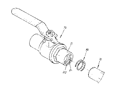
Fig. 4 is a diagram showing the exploded components of the first embodiment of
the
present invention;
Fig. 4A is a diagram partially showing a second embodiment of the present
invention;
Fig. 5 is a diagram showing the assembly and location of the soldering
material in the
spiral groove in a connection pipe of a valve;
Fig. 6 is a diagram showing the melting of solder material in the spiral
groove of the
present invention;
Fig. 6A is an enlarged diagram showing the melting of solder material in the
spiral
groove so as to firmly retain a pipe in place in a valve.
Refernng to Figs. 4, the improved welding connection tube 21 for use in a
common valve or multi-tube connector is used in combination with a metallic
tube 10,
a valve head or a multiple-tube connector 20 and a soft solder strip 30. The
welding
connection tube 21 of a valve or a metallic mufti-tube connector 20 is
provided with a
continuous spiral groove 211 having at least two consecutive ringed areas. At
the edge
of the connection tube 21 is disposed a leading cut 212.
Referring further to Fig. 4A, the connection tube 21 have a continuous
spiral or helical groove 211 which extends in such a manner that the outer
surface of
the connection tube 21 forms a continuous spiral protrusion thereon.
The soft solder strip 30 is flexible to be bent and its length is shorter than
the length of the spiral groove 211 of the connection tube 21 of the valve or
multi-
tube connector 20.
4

CA 02233050 1998-03-25
Referring to Fig. 5, the assembly of the present invention is shown in
detail. At the beginning of the assembly, the soft solder strip 30 is first
spirally moved
forwardly, along the spiral groove 211, into the connection tube 21 of the
valve or
mufti-tube connector 20 from the leading cut 212 at the starting point of the
edge of
the connection tube 21 until the end of the soft solder strip 30 reaches the
rear end
of the spiral groove 211 of the connection tube 21.
Referring further to Figs. 6, 6A, the sectional diagram of the connection
tube 21 of the present invention shows that the soft solder strip 30 is melted
by heat to
axially distribute in-between the ringed area of the spiral groove 211 of the
connection tube 21 of a valve or mufti-tube connector 20 so as to firmly
retain the
inserted metallic tube in place in one aspect and to effectively prevent
liquid from
leaking via the welding spots in another aspect.
It can be apparently seen that the present invention has the following
advantages in practical use:
l.The assembly and welding operations of the present invention are simple and
quick,
effectively decreasing the cost and labor in practical use.
2.The inserted tube 10 and the connection tube 21 of a valve or mufti-tube
connector
20 are welded together by way of a multiple-spot connection, making the
strength and
leak-proof capacity of the welding connection increased
s

Dessin représentatif
Une figure unique qui représente un dessin illustrant l'invention.
États administratifs

2024-08-01 : Dans le cadre de la transition vers les Brevets de nouvelle génération (BNG), la base de données sur les brevets canadiens (BDBC) contient désormais un Historique d'événement plus détaillé, qui reproduit le Journal des événements de notre nouvelle solution interne.

Veuillez noter que les événements débutant par « Inactive : » se réfèrent à des événements qui ne sont plus utilisés dans notre nouvelle solution interne.

Pour une meilleure compréhension de l'état de la demande ou brevet qui figure sur cette page, la rubrique Mise en garde , et les descriptions de Brevet , Historique d'événement , Taxes périodiques et Historique des paiements devraient être consultées.

Historique d'événement

Description Date
Le délai pour l'annulation est expiré 2001-03-26
Demande non rétablie avant l'échéance 2001-03-26
Réputée abandonnée - omission de répondre à un avis sur les taxes pour le maintien en état 2000-03-27
Demande publiée (accessible au public) 1999-09-25
Inactive : Page couverture publiée 1999-09-24
Symbole de classement modifié 1998-08-01
Inactive : CIB attribuée 1998-08-01
Inactive : CIB en 1re position 1998-08-01
Inactive : Certificat de dépôt - RE (Anglais) 1998-06-05
Demande reçue - nationale ordinaire 1998-06-04
Toutes les exigences pour l'examen - jugée conforme 1998-03-25
Exigences pour une requête d'examen - jugée conforme 1998-03-25

Historique d'abandonnement

Date d'abandonnement Raison Date de rétablissement
2000-03-27

Historique des taxes

Type de taxes Anniversaire Échéance Date payée
Taxe pour le dépôt - petite 1998-03-25
Enregistrement d'un document 1998-03-25
Requête d'examen - petite 1998-03-25
Titulaires au dossier

Les titulaires actuels et antérieures au dossier sont affichés en ordre alphabétique.

Titulaires actuels au dossier
CHUNG CHENG FAUCET CO., LTD.
Titulaires antérieures au dossier
HSI-CHIA KO
Les propriétaires antérieurs qui ne figurent pas dans la liste des « Propriétaires au dossier » apparaîtront dans d'autres documents au dossier.
Documents

Pour visionner les fichiers sélectionnés, entrer le code reCAPTCHA :


Pour visualiser une image, cliquer sur un lien dans la colonne description du document. Pour télécharger l'image (les images), cliquer l'une ou plusieurs cases à cocher dans la première colonne et ensuite cliquer sur le bouton "Télécharger sélection en format PDF (archive Zip)" ou le bouton "Télécharger sélection (en un fichier PDF fusionné)".

Liste des documents de brevet publiés et non publiés sur la BDBC .

Si vous avez des difficultés à accéder au contenu, veuillez communiquer avec le Centre de services à la clientèle au 1-866-997-1936, ou envoyer un courriel au Centre de service à la clientèle de l'OPIC.


Description du
Document 
Date
(aaaa-mm-jj) 
Nombre de pages   Taille de l'image (Ko) 
Abrégé 1998-03-24 1 24
Description 1998-03-24 5 181
Revendications 1998-03-24 1 32
Dessins 1998-03-24 3 59
Dessin représentatif 1999-09-13 1 9
Courtoisie - Certificat d'enregistrement (document(s) connexe(s)) 1998-06-04 1 116
Certificat de dépôt (anglais) 1998-06-04 1 163
Rappel de taxe de maintien due 1999-11-28 1 111
Courtoisie - Lettre d'abandon (taxe de maintien en état) 2000-04-24 1 183