Note : Les descriptions sont présentées dans la langue officielle dans laquelle elles ont été soumises.
CA 02233723 1998-04-01
WO 97/13378 PCT/IL96/00120
APPARATUS AND ~IETHOD FOR DETERMINING AND USING CHANNEL
STATE I~FORMATION
B~ck~,~ronnd Of The lnvention
.,
The present invention relates to wireless communications. More particularly, it
relates to appa~ s and methods for determining the state of a frequency channel in a
~,vireless communication channel and for using the channel state illrC~I~llaLiOll.
As is well known, a frequency channel in a wireless communication channel is
subject to many sources of degradation. Thus, communication signals will not always be
communicated properly on a frequency channel. When operating a wi,~less
communication system, it is desirable to be able to determine the "state" of a frequency
channel in order to determine the li~;elihood of acceptable comm--nic~tic-n on the
frequency channel. While channel estimators are known in the art, none ~deq~telyperforms the tasks of determining the state of a frequency channel. Another shortcoming
of existing communication systems is found in the usage of channel state inro, Illalion~
Thus, apparatus and method for determining the state of a frequency channel are
needed. Further, apparatus and method for using the channel state illrollllalion to
control the operation of the communication system to achieve improved comml-ni~tion
are also needed.
Snn-m~rv Of The ln~ention
The present invention provides apparatus and method for determining and using
channel state information. In accordance with one aspect of a ,vlerell~d embodiment of
the present invention, channel state information is derived from a set of communication
symbols received during an individual time slot, although any set of commllnic~tion
signals or even a single communication signal can be used. For each of the received
comm--nication symbols, QPSK modulated symbols are hard detected to determine the
actual transmitted signal. Then, the in phase and quadrature components of the received
communication symbols in the plane of the modulation points are determined. Next, the
sum of the in phase components is determined and the sum of the absolute value of the
quadrature components is determined. The channel state is then determined from the
SUBSTITUTE SH EET (RULE 26)
CA 02233723 1998-04-01
WO 97/13378 PCT/IL96/00120
ratio of the sum of the in phase components to the sum of the absolute value of the
quadrature components. The present invention also contemplates determining the
channel state from the phase error of the received signals from the modulation points.
The present invention further contemplates determining the channel state from the
distance error of received signals from the modulation points.
In accordance with another aspect of the present invention, method and apparatusfor erasing communication signals in accordance with the channel state are provided. In
accordance with the method, the channel state is determined when the comm~nic~tion
signal is received and then signals are erased if the channel state is not better than a
predetermined level.
In accordance with a further aspect of the present invention, method and apparatus
for selecting one of two communication signals for processing when diversity signals are
received. In accordance with the method, a first channel state is determined when the
first of two diversity communication signals is received and a second channel state is
determined when the second of the two diversity communication signals is received.
Then, based on the values of the first and the second channel states, one of the two
diversity communication signals is selected for further processing.
The invention will now be described in connection with certain illustrated
embo~limçnts; however, it should be clear to those skilled in the art that various
modifications, additions and subtractions can be made without departing from the spirit
and scope of the claims.
Description Of The Dr~win~s
FIG. 1 illustrates a wireless communication system in which the apparatus and
method ofthe present invention is used;
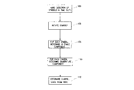
FIG. 2 shows the steps used to determine channel state by using the in phase andquadrature components of a received communication signal;
FIG. 3 illustrate a modulation plane and the determination of channel state by using
the in phase and quadrature components of received signals as in FIG. l;
FIGS. 4 and 5 illustrate an alternate process of determining channel state by using
phase error of received signals;
SUBSTITUTE SHEET (RULE 26)
,
-
CA 02233723 1998-04-01
WO 97/13378 PCT/IL96/00120
FIGS. 6 and 7 illustrate a process for determining channel state by using the
Euclidean distance error of received signals and the respective modulation points;
FIG. 8 illustrates the processing apparatus in the subscriber units used to determine
charmel state in accordance with any of the above processes;
FIG. 9 illustrates the process in accordance with another aspect of the present
invention wherein communication signals from one of two diversity ch~nnf~lc are selected
for proceccinp
FIG. 10 illustrates the process in accordance with one aspect of the present
invention wherein communication signals are erased; and
FIG. 11 illustrates a metric decision zone.
Description Of Tlle Pref~rred Embod iment
FIG. 1 illustrates a wireless communication system I in which the apparatus and
method of the present invention can be used. A base station 2 establishes
communications with and between a plurality of mobile or portable subscriber units 4 and
a plurality of dispatch stations 6. The subscriber units 4 have the ability to comm--nic~te
with each other and with the dispatch station 6. The communication functions provided
preferably include telephony, dispatch, one to one communications, data communications
and other communication functions. The communication links are provided between the
above described components and over the PSTN.
The system of FIG. 1 preferably establishes communications over a plurality of
frequency ~.h~nnçlc and in a plurality of time slots. The communications over the
frequency channels are preferably broken into packets which are "hopped" across the
frequency channels -- thus, a communication is transmitted over more than one
frequency channel in accordance with a predetermined sequence, as described in United
States Patent No. 5,408,496, which is hereby incorporated by reference. Such a system
is commonly referred to as a frequency hopping system.
The comml-nications can also be "hopped" across the plurality of time slots. In
this case, different parts of a communication are transmitted in different time slots, again
in accordance with a predetermined sequence. Further, the communication system 1 is
shown as a sectorized system having three sectors 8 to 10. The hopping sequences used
SUBSTITUTE SHEET (RULE 26)
CA 02233723 1998-04-01
WO 97/13378 PCT/IL96/001~0
in the sectors 8 to 10 are preferably orthogonal, as explained in United States Patent No.
5,408,496. The present invention, however, is not limited to sectorized comm-lnic~tion
systems or to frequency and/or time hopped communication systems.
When a subscriber unit 4, a dispatch station 6 or a base station 2 receives a signal,
it is desirable to determine the state of the communication channel that the signal was
received on. In FIG. 2, the preferred steps used to determine channel state, in
accordance with a one embodiment of the present invention, are illustrated. In the first
step 100, after the received signals are demodulated, communication signals from one of
the plurality of time slots in the time slotted communication system of FIG. 1 are
detected.
For illustrative purposes only, assume that communication signals received in the
time slot consists of thirty-eight QPSK modulated symbols, each symbol falling into one
of four quadrants in a modulation plane, the quadrant being specified by two bits. For
example, in FIG. 3, a QPSK modulation plane having four modulation points 102 to 105
in quadrants 0 to 3, respectively, is shown. For each received symbol, the two bits in the
symbol deterrnine which quadrant the symbol belongs in.
After demodulation, as part of step 100, hard detection -- a well known process --
assigns each symbol to one of the four quadrants. This process simply deterrnines the
value of the received symbol and makes the quadrant assignment. Thus, in FIG. 3,symbol S1, whose bits are 00, is assigned to quadrant 0. Symbol S2, whose bits are 01,
is ~igned to quadrant 2. Symbol S3, whose bits are 11, is assigned to quadrant 3.
Symbol S4, whose bits are 10, is assigned to quadrant 1. This process is performed
thirty-nine times, one time for each symbol in the time slot.
Next, in step 106, each symbol is rotated to a selected one of the four quadrants,
preferably quadrant 0. This process allows uniform and simpler processing of thereceived communication signals in accordance with the present invention. If quadrant 0
is sPlected as the quadrant to which all symbols are rotated to, then the symbols are
rotated according to the following:
(1) If the symbol is in quadrant 0, the symbol is not rotated;
(2) If the symbol is in quadrant 2, 90~ is added to the symbol phase to rotate the symbol
to quadrant 0;
SUBSTITUTE SHEET(RULE ~6)
CA 0 2 2 3 3 7 2 3 1 9 9 8 - 0 4 - o l
WO 97/13378 PCT/IL96/00120
(3) If the symbol is in quadrant 3, 180~ is added to the symbol phase to rotate the symbol
to quadrant 0; and
(4) If the symbol is in quadrant 1, 270~ is added to the symbol phase to rotate the syrnbol
to quadrant 0.
Referring to FIG. 3, this process is illustrated with respect to symbols Sl to S4.
Since symbol S1 is in quadrant 0, nothing is done and symbol Sl remains in quadrant 0.
Since symbol S2 is in quadrant 2, 90~ is added to rotate symbol S2 to quadrant 0. Since
symbol S3 is in quadrant 3, 1~0~ is added to rotate symbol S3 to quadrant 0. Since
symbol S4 is in quadrant 1, 270~ is added to rotate symbol S4 to quadrant 0. Again, this
process is performed thirty-nine times, one time for each symbol in the time slot.
Once all the symbols from a time slot have been rotated to the same quadrant, instep 108, the in-phase component of each symbol in the x-y plane, which has axesintersecting the modulation points in the modulation plane as shown in FIG. 3, is
determined. Since the symbol is a complex number, this is preferably performed by
taking the real component of each symbol, Re(Si), where Si are the symbols in a time
slot. Then, in step 110, the quadrature component of each symbol in the x-y plane is
determined. Again, since the symbols are complex numbers, this is preferably done by
taking the im~in~ry component of each symbol in the time slot: Imag(Si). In FIG. 3, the
calculation of the in-phase component, Real(S 1), and the quadrature component,
Imag(Sl), for one symbol, S1, is illustrated. It is understood however that this process is
preferably performed on each rotated symbol in a time slot.
In step 1 12, the channel state of the frequency channel during the time slot that the
symbols were received on is determined from the ratio of the sum of the in-phasecomponents to the sum of the absolute value of the quadrature components. Thus, the
in-phase component from each symbol in the time slot is summed. Then, the absolute
value of the quadrature component from each symbol is summed. Then the channel state
is the ratio of the sum of the in-phase components to the sum of the absolute value of the
quadrature components. Thus, channel state, CS, is preferably determined as follows:
~ Real (Si)
Cs = Slor
l Im ag(Si)l
slOI
SUBSTITUTE SHEET (RULE 26)
,
CA 02233723 1998-04-01
WO 97/13378 PCT/IL96/00120
where Si are the symbols in the time slot. In the equation above, the absolute value is
used to m~int~in channel state as a positive number. Other m~th~m~tic~l functions can
be used to perforrn the same task. ~~
In the above equation, it is apparent that the higher the value of CS, the higher the
quality of the channel state. Conversely, the lower the value of CS, the lower the quality
of the channel state.
In accordance with the present invention, two points -- the norninal modulation
point and the received signal point -- are compared to deterrnine channel state. In
accordance u~ith this embodiment of the present invention, the calculation of the in-phase
and quadrature components, therefore, provides a measure of the variance or error
between the received symbol and the actual transmitted symbol as determined by hard
detection. If the symbols in a time slot show a small deviation, the channel state is
"good" since there was not much distortion. If, on the other hand, there is a lot of
deviation in the received symbols, the channel state is "poor".
It will be appreciated that while the above describes a plefel~ed embodiment of
determining channel state by processing the symbols in a time slot, the invention has
broader applications. The above described processing can be perforrned on a single
commllniç~tion signal to determine the state of the communication channel on which the
signal was received, although the averaging of the received symbols yields a better
indication of the channel state. Thus, it is apparent that the processing need not be
restricted to the symbols in a time slot -- more or less symbols can be used as desired.
Also, the use of the previously described processing steps is not limited to frequency
hopping and time hopping communication systems -- they may be used on any type of
commllnic~tion system. In addition, if a plurality of symbols are used, they need not be
rotated to one quadrant in the modulation plane as described above; instead the
processing can be done within the quadrant that the symbol belongs to and the results
averaged accordingly. Further, the processing of the present invention can be used with
any modulation scheme.
FIGS. 4 and 5 illustrate the determination of the channel state via an alternateembodiment. Referring to FIG. 4, the first two steps 120 and 122 are the same as steps
100 and 106 previously described with respect to FIG. 2. Thus, in step 120, hard
SUBSTITUTE SH EET (RULE 26)
CA 02233723 1998-04-01
WO 97/13378 PCT/IL96/00120
detection ofthe demodulated received symbols is perforrned to deterrnine the modulation
point of the demodulated received signal and, in step 1 72, all of the received signals from
a time slot are rotated to one quadrant in the modulation plane. The rotation of four
'~ syrnbols S1 to S4 are illustrated in FIG. 5.
In step 124, the phase error of each rotated symbol is determined. Referring to
FIG. 5, it is seen that the phase error, ~(lerr), for one demodulated received symbol, Sl,
is the phase between modulation point 176, ~(mod), and the symbol Sl, ~(S1):
~(1 err) = ~(S I ) - O(mod)
A~er the phase error for each demodulated received symbol is determined, in step128, the average phase error of the symbols within a slot is determined using the absolute
value of the phase error:
~ (avg) = ~l~(ier~ (Si) - t~(mod)
slO~ slO~
where i is the symbol number in a time slot and ~ (Si) is the phase of each rotated symbol
Si within the time slot.
Alternatively, the average phase error of the symbols within a slot can be
determined using the square of the phase error from each symbol:
~ ~avg)= ~ (~(ie77))~ (Si)-~(mod))2
slO~ .~lor
where i is the symbol number in a time slot and ~ (Si) is the phase of each rotated symbol
Si within the time slot.
Next, in step 130, the channel state, CS, is determined in accordance with ~(avg).
The exact relationship between the channel state and the average phase error (i.e. what is
"good" and what is "poor") is preferably determined empirically for each communication
system, but in general, the greater the average phase error, the worse the channel state
and the lower the average phase error, the better the channel state.
FIGS. 6 and 7 illustrate the determination of the channel state via another alternate
embodiment. Referring to FIG. 6, once again, the first two steps 140 and 142 are the
same as steps 100 and 106 previously described with respect to FIG. 2. Thus, in step
SUBSTITUTE SHEET (RULE Z6)
-
CA 02233723 1998-04-01
WO 97/13378 PCT/IL96/00120
140, hard detection of the received symbols is performed to determine the modulation
point of the received signal and, in step 142, all of the received symbols from a time slot
are rotated to one quadrant in the modulation plane. The rotations of four symbols S 1 to
S4 are illustrated in FIG. 7.
In step 144, the Euclidean distance error of each rotated signal is deterrnined.Referring to FIG. 7, it is seen that the Euclidean distance error, El, for one received
signal, S1, is the distance between the modulation point of the quadrant that the
received signal is in -- in this case modulation point 146 -- and the signal S1. Then, in
step 148, the absolute value of the Euclidean distance error for each received signal is
determined. In step 150, the channel state, CS, is determined from the average distance
error Ei of symbols within a time slot:
CS = ~ IEi
s~O,
In step 152, it is further preferred to normalize CS to the average absolute value of
the symbols in a time slot:
-
~ lSil
s10,
As before, the exact relationship between the channel state and the averageEuclidean distance error is preferably determined empirically for each communication
system, but in general, the greater the average distance error, the worse the channel state
and the lower the average distance error, the better the channel state.
Referring to FIG. 8, the receiving, processing and display equipment of the
subscriber unit 4 is illustrated. The receive equipment of the base station 2 and the
(lisp~t~l station 6 is substantially similar. The transmit circuitry, which is not important
to the present invention, includes a transmitter 200 and a gain control circuit 202 which
are controlled, in part, by a frequency s~ nthesizer 204. Signals are transmitted through a
duplexer 206 and an antenna 208.
On the receive side, communication signals are received on the antenna 208 and on
a second ~qntPnna 210. Two receivers 212 and 214 receive the signals from the antennas
SUBSTITUTE SH EET (RULE 26)
-
CA 02233723 1998-04-01
WO 97/13378 PCT/IL96/00120
208 and 210, respectively. The frequency channel of reception is progldl,ln,ed into the
,ecei~ 212 and 214 by the syntheci~er 204. The receivers 212 and 214 are gain and
frequency controlled by a circuit 216.
The received signals from both ~ntenn~c 208 and 210 are preferably sent to the
modem 218. The modem 218 converts the received signals to digital signals. The
modem 218 ~leÇel~bly includes a digital signal processor (DSP), preferably Analog
Devices 2111, 2171 or 2181, and a ASIC device 230. These devices process the signals
received from both receivers 212 and 214 in accordance with the previously described
steps.
The processing is controlled by a controller 220. The processed signals are further
processed to extract voice and other info..l.&lion by a voice processing package (VPP)
222 and the processed communication signals are provided to a user interface 224through the interface 226. The user interface 224 incl~ s the usual devices found in
subscriber units, inf.llltling a display, speakers and microphones.
The circuitry of FIG. 8, can be used to calculate the variation or error associated
with received commnnic~tion signals in accordance with any of the previously described
processes. Thus, the circuitry of FIG. 8 can calculate in-phase and quadrature
components, phase error and/or distance errors associated with the received signals.
The channel state CS that is computed from received signals by the processing
circuitry of FIG. 8 can be utilized to select between the two signals simult~neously
received on the ~ntenn~c 208 and 210 and by the receivers 212 and 214, respectively.
This reception of dual signals is commonly referred to as "diversity" reception.Referring to FIG. 9, the steps for making the selection between the two diversity
signals, which are received at the same time, are illustrated. In step 300, the charmel
state for the first receive channel, CSI, which is generated by any of the previously
described processes or by any other process, from the signals (or signal) received on
~ntenn~ 208, is determined. In step 302, the channel state for the second receive
~~.h~nnlol, CS2, which is generated as previously described or by any other process, from
the signals (or signal) ,~ceived on antenna 210, is determined. Then in step 304, the
channel states from each receive channel are compared. If we assume that the process of
SUBSTITUTE SHEET (RULE 26)
,
CA 02233723 1998-04-01
WO 97/13378 PCT/IL96/00120
FIGS. 2 and 3 are used to calculate the channel state for each receive çh~nnel~ then the
following comparison is made:
CS1 > CS2?
If CS1 is greater than CS2, then in step 306, channel 1 is selected. Thus, the
signals from antenna 208 are selected for processing. On the other hand, if CSl is not
greater than CS2, channel 2 is selected so that the signals from the ~ntçnn~ 210 are
selected for processing (step 308). As before, the processing is perforrned by the
circuitry of FIG. 8, in particular, in the digital signal processor in the modem 218.
The selection of signals from one of two channels for processing is preferably done
every time channel states are recalculated. Thus, where the channel states for the
diversity channels are calculated for each time slot, it is the signals from the time slot of
one of the channels that are selected for processing. A new selection is then made for
every time slot. If channel state is determined from another period of signals, by way of
example only, from a single signal, then the signals from the period that is used to
calculate channel state are the ones selected for processing.
The channel state CS that is computed from received signals by the processing
circuitry of FIG. 8 can also be utilized to erase signals which are not received with some
minimurll confidence level. The confidence level is preferably determined in accordance
with the channel state.
Referring to FIG. 10, the preferred steps for perforrning erasures of signals that are
not received with some minimum confidence level are shown. In step 350, the channel
state of a receive signal or of a group of receive signals -- for example, the signals in a
selected time slot -- is determined. This can either be the channel state of the selected
one of the two receive channels or it can be the channel state of a single receive çh~nnf~.l
Then, in step 352, the channel state is compared to a threshold, th. If the comparison
fails, that is, if the channel state is not better than some value represented by the
threshold, it is preferred to erase the signal in step 354. If the comparison passes, that is
if the channel state is better than some value represented by the threshold, in step 356,
SUBSTITUTE SHEET (RULE 26)
_
CA 02233723 1998-04-01
WO 97/13378 PCT/IL96/00120
the signal is passed on for further processing. Whether "better" means greater or less
than the threshold depends on the process used to determine channel state.
The number of signals erased plt:felably coincides with the number of signals used
to c~lc~ te the channel state. Thus, where the channel state is calculated from signals in
a time slot, it is the signals from the time slot of one of the rh~nn~lc that are erased in
step 354. If channel state is determined from another period of signals, then the signals
from the period that is used to ç~lc~ te channel state are the signals that are erased in
step 354. So for example only, if channel state were c~lc~ te based on a single received
signal, then it is pl~r~-led to erase only the single signal in step 354.
The preferred value of the threshold, th, depends on the method of calc~ ting
channel state. If channel state is calculated via the in-phase and quadrature components
of the received signals in a time slot, then the threshold is preferably 3.5 and the erasure
is made in step 354 if the channel state of received signals in a time slot falls below that
number. If the channel state is calculated via the phase error of the received signals in a
time slot, then the threshold th is preferably 0.085 and the erasure is made in step 354 if
the channel state of the received signals in the time slot exceeds that number.
In step 354, the erasure is preferably made by setting a metric, which is a number
associated with each received signal that ,e,ult:senLs the confidence level that the received
signal was properly received, to a predetermined value, typically the lowest value. When
the circuitry of FIG. 8 processes the received signals, it preferably erases the signals with
the lowest metric by setting those signals to zero.
In accordance with another embodiment of the present invention, a commllnic~tiondevice receiving a communication signal performs two measures of channel state and
uses one of the channel states to perform diversity selection and the other channel state
to perform erasures. In a preferred embodiment, the channel state determined by phase
error measurements (FIGS. 4 and 5) is used to perform erasures of poorly received
signals while the channel state determined by di~t~nce error measurements (FIGS. 6 and
7) is used to select one ofthe two diversity ch~nnPI~
SUBSTITUTE SHEET(RULE 26)
CA 02233723 1998-04-01
WO 97/13378 PCT/IL96/00120
Pseudocode
The previously described steps of determining channel state from the in-phase and
quadrature components of received signals from two ch~nn~?ls~ the steps of st?lectinE
between diversity signals and the steps of erasing signals which are not received with
some .~ .- confi~ nr.e level, are further described by the following pseudocode:
Calculate Channel State
CS X = 0.0 Tniti~1i7e channel state variables
CS_Y = 0.0
for I: = l to 38 do For each symbol in a time slot
Begin
U:=R(I)R*(I-1) Perform for di~relenlial detection
(di~ert;nl detection equations are used
for di~el e"~ detection scht~ F,5)
MSD, MHD:=according to routine Generate metrics, MSD and MHD, for
so~ and hard decisions, lespc~Li~ely; see
the metrics generation routine
MET0[i] = TABLEl(MSD); Apply MSD to Table l (see below)
which is an example of the metrics
p,e~l,ed for a specific communication
system. The table generates a 3 bit
metric, MET0[i], where i is the symbol
number within the time slot being
processed. One bit of the metric
MET0[i] is I and two bits are the
confidence level.
METl [i] = TABLE2(MSD); Apply MSD to Table 2 (see below). The
table generates a 3 bit metric, METl[i],
where i is the symbol number within the
SUBSTITUTE SHEET (RULE 26)
,
CA 02233723 1998-04-01
WO 97/13378 PCT/IL96/00120
time slot being processed. One bit of the
metric MET I [i] is Q and two bits are the
confidence level.
If MHD = 0, then W:=U ~ (I j); Rotate to quadrant 0 based on hard
decision
If MHD = 1, then W:=U ~ (- l j);
If MHD = 3, then W:=U- (-l+j);
If MHD = 2, then W:=U- (l+j);
CS_X:=CS_X +Re(W) Sum in-phase components of rotated
signal
CS_Y:=CS_Y + IImag(W)I Sum absolute value of quadrature
components of rotated signal
end;
Perform Erasure
If CS_X < CS_Y ~ CSmin, then CSmin is the threshold to which
CS_X/CS_Y is compared to
Begin
For I:=l to 38 do For each symbol in a time slot, erase by
setting confidence level bits to 00
Begin
if MET0[i] < 4 then MET0[i] :=0 For I = O (represented by 0XX, i.e. < 4,
where 0 is the bit and XX is the
confidence level associated with the bit)
erase by setting confidçnçe level to the
minimllm value, 00, which causes the
digital signal processor to erase the bit.
~ The result is MET 0[i] = 0.
if MET0[i] > 3 then MET0[i]:=4 For I = 1 (represented by lXX, i.e. > 3,
SUBSTITUTE SHEET (RULE 26)
CA 02233723 1998-04-01
WO 97/13378 PCT/IL96/00120
where 1 is the bit and XX is the
confidçnce level associated with the bit)
erase by setting confidence 1evel to the
minimllm value, 00, which causes the
digital signal processor to erase the bit.
The result is METO[i] = 4.
if MET1[i] < 4 then MET1[i]:=0 For Q = O (represented by OXX, i.e. < 4,
where O is the bit and XX is the
confidence level associated with the bit)
erase by setting confid~nçe level to the
miniml-m value, 00, which causes the
digital signal processor to erase the bit.
The result is MET lti] = O.
if MET1 [i] > 3 then MET1 [i]:=4 For I = 1 (represented by 1XX, i.e. > 3,
where 1 is the bit and ~ is the
confidence level associated with the bit)
erase by setting confidence level to the
minimnm value, 00, which causes the
digital signal processor to erase the bit.
The result is M~TOti] = 4.
end;
end;
Perforrn diversity selection
AO := CS_XO- CS_Y1 0 and 1 indicate the diversity ch~nnel~
A1 := CS_X1- CS_YO
For i=1 to 38
Set M~i] = MET1[i]:METO[i] M[i] becomes a six bit metric
repr.osçn~ing I and Q and the confiAPnce
levels. For each i, select the values from
SUBSTITUTE SHEET (RULE 26)
-
CA 02233723 1998-04-01
WO 97/13378 PCT/IL96/00120
channel 0 if A0 > Al and select the
values from channel 1 if Al 2 A0.
Metrics Generation Routine
Can be c~lall~ted via table but the
following generator saves DSP memory
Calculate III = IRe(lJ)
C~lMll~te IQI = IIm~l
Determine a section S in the first quadrant Referring to FIG. 11, there are 3
sectors in each quadrant. The sector
that a symbol falls in is determined
here. The 3 sectors are identified by
S=0, 4, and 44.
- If IQI < lIl tan 30~, then S=44
If lIl ~ tan 30~< IQI ~ tan 60~ then S=0
If lIl ~ tan 60~ < IQI, then S=4
Calculate y = (Q2 + I2)'n
Calculate rings:
R=3 0 < ~ < 1.225.10-3 The boundaries should be less than l;
see FIG. 11 for the generated metric
decision zones, incllltiing the five
possible rings.
R=2 1.225.10-3 <y < 4.9.10-3
R=1 4.9.10-3< y < 0.0196
R=0 0.0196 <~ < 0.49
- SUBSTITUTE SH EET (RULE 26)
CA 02233723 1998-04-01
WO 97/13378 PCT/IL96/00120
R=3 ~ > 0.49
C~lc~ te metrics:
MSD = S+R and MHD = 0: Q 2 O, I 2 0 The metrics (ME~) for hard
detection and MSD for soft
detectinn) are determined here
based on the values of S and R.
MHD places the signal on one of
four quadrants. MSD places the
signal on the metric decision zone
in FIG. 1. For example, if MHD
=1 (i.e. quadrant 1) and S = 44 and
R =1, then MSD =17. See zone 17
in quadrant 1 of FIG. 11.
MSD = [(12-S) mod 48] + R and MHD = 1, mod indicates modular arithmetic
for Q 2 O, I~O
MSD = [(24+S) mod 48] + R and ME~D =3,
for Q~O, I<O
MSD = [(36-S) mod 48] + R and MHD =2,
for Q<O, I > O
16
SUBSTITUTE SHEET (RULE 26)
CA 02233723 1998-04-01
WO 97/13378 PCT/IL96/00120
TABLEl-LSB Metrics
IN OUT IN OUT
0 3 24 7
2 25 6
2 1 26 5
3 0 27 4
4 2 28 6
1 29 5
6 0 30 4
7 0 31 4
8 6 32 2
9 5 33
4 34 0
11 4 35 0
12 7 36 3
13 6 37 2
14 5 38
4 39 0
16 7 40 3
17 6 41 2
18 5 42
19 4 43 0
7 44 3
SUBSTITUTE SHEET (RULE 26)
CA 02233723 1998-04-01
WO 97/13378 PCT/IL96/00120
21 6 45 2
22 5 46
23 4 47 0
TABLE 2 - MSB Metr~cs
rN ou r rN ou r
0 3 24 7
2 25 6
2 1 26 5
3 0 27 4
4 3 28 7
2 29 6
6 1 30 5
7 0 31 4
8 3 32 7
9 2 33 6
1 34 5
11 0 35 4
12 3 36 7
13 2 37 6
14 1 38 5
0 39 4
16 2 40 6
SUBSTITUTE SHEET (RULE 26)
CA 02233723 1998-04-01
WO 97/13378 PCT/IL96/00120
17 1 41 5
18 0 42 4
19 0 43 4
6 44 2
21 5 45
22 4 46 0
23 4 47 0
An example will now be given that illustrates the processing of one symbol and the
effect of an erasure on that symbol. Suppose that the first symbol in a time slot, Sl, is
received and that, when applied to the metric generation routine, yields S = 44, R = 1
and MHD = 1. Applying these facts to the MSD equation:
MSD = [(12 - S) mod48] + R= [(12 - 44) mod 48] + 1 = 17
Thus, the symbol S 1 falls in zone 17 in quadrant 1 in FIG. 11.
Next MET0[1] and MET1[1] are generated by applying MSD to TABLE 1 and
TABLE 2, respectively:
MET0[1] = 6 = 110
MET1[1] = 1 = 001
The first bit of MET0[1] specifies I = 1 and the next two bits, 10, specify a confidence
level (00 is the lowest level, 11 is the highest). The first bit of MET1[1] specifies Q = 0
and the next two bits specify a confidence level.
Erasures are made, if at all, once all of the symbols in the time slot have beenprocessed. If the channel state falls below a threshold, CS min, then the confiden~e bits
for all symbols in a time slot, Si, are set to "null values", which are of low level of
confidPnce, like 00. The processing then changes the values of the I and the Q bits to
null metrics which do not contribute to an erroneous decision at the error correcting
SUBSTITUTE SH EET (RULE 26)
CA 02233723 1998-04-01
WO 97/13378 PCT/IL96/00120
process. F~enti~lly~ the erasure means that the I and Q information content from the
time slot is not used. Thus, if an erasure needs to be made, the following occurs:
MET0[1] = 4 = 100
METl[l] = O = 000
This is repeated for all symbols in the time slot.
It is understood that changes may be made in the above description without
departing from the scope of the invention. It is accordingly int~n~ed that all matter
contained in the above description and in the drawings be interpreted as illustrative rather
than limiting
SUBSTITUTE SHFET (RULE 26)