Sélection de la langue

Search

Sommaire du brevet 2234378 

Énoncé de désistement de responsabilité concernant l'information provenant de tiers

Une partie des informations de ce site Web a été fournie par des sources externes. Le gouvernement du Canada n'assume aucune responsabilité concernant la précision, l'actualité ou la fiabilité des informations fournies par les sources externes. Les utilisateurs qui désirent employer cette information devraient consulter directement la source des informations. Le contenu fourni par les sources externes n'est pas assujetti aux exigences sur les langues officielles, la protection des renseignements personnels et l'accessibilité.

Disponibilité de l'Abrégé et des Revendications

L'apparition de différences dans le texte et l'image des Revendications et de l'Abrégé dépend du moment auquel le document est publié. Les textes des Revendications et de l'Abrégé sont affichés :

  • lorsque la demande peut être examinée par le public;
  • lorsque le brevet est émis (délivrance).
(12) Demande de brevet: (11) CA 2234378
(54) Titre français: RECIPIENT
(54) Titre anglais: CONTAINER
Statut: Réputée abandonnée et au-delà du délai pour le rétablissement - en attente de la réponse à l’avis de communication rejetée
Données bibliographiques
(51) Classification internationale des brevets (CIB):
  • B65D 8/14 (2006.01)
  • B65D 45/16 (2006.01)
  • E03B 3/03 (2006.01)
(72) Inventeurs :
  • GRAF, OTTO PETER (Allemagne)
(73) Titulaires :
  • OTTO PETER GRAF
(71) Demandeurs :
  • OTTO PETER GRAF (Allemagne)
(74) Agent: SMART & BIGGAR LP
(74) Co-agent:
(45) Délivré:
(22) Date de dépôt: 1998-04-06
(41) Mise à la disponibilité du public: 1998-10-11
Licence disponible: S.O.
Cédé au domaine public: S.O.
(25) Langue des documents déposés: Anglais

Traité de coopération en matière de brevets (PCT): Non

(30) Données de priorité de la demande:
Numéro de la demande Pays / territoire Date
97 105 987.8 (Office Européen des Brevets (OEB)) 1997-04-11

Abrégés

Abrégé français

Le récipient se compose de deux coquilles qui se font face et qui sont assemblées par leur bord ouvert au moyen de structures de fixation coniques. A cette fin, chaque coquille comprend une pluralité de demi-cônes distribués le long de la circonférence. Deux demi-cônes opposés des deux coquilles se complètent pour former un cône entier. Une bride conique fournie séparément se glisse par-dessus chaque cône entier, laquelle enserre le cône entier et presse l'un contre l'autre les deux demi-cônes de chaque cône entier et conséquemment les deux bords ouverts. Enter the French Abstract here.


Abrégé anglais


The container consists of two shells which face
each other and are mounted to each other at their port edges
by means of wedge type fastener structures. To this end each
shell includes a plurality of semi-wedges arranged distributed
along the circumference. Two opposite semi-wedges of the
two shells complete themselves to a complete wedge. A
separately provided wedge clams is slid over every complete
wedge, which wedge clamp grips around the complete wedge and
presses the two semi-wedges of each complete wedge and
accordingly the two port edges together.

Revendications

Note : Les revendications sont présentées dans la langue officielle dans laquelle elles ont été soumises.


CLAIMS
1. A container, having a lower shell with an
upper port edge, and having an upper shell with a lower port
edge, and having coupling structures by means of which the
two shells are coupled along their port edges, which
container features a longitudinal axis which is common to both
shells, which longitudinal axis extends vertically when the
container is in its operational position, wherein both port
edges comprise a plurality of semi-wedges located distributed
along their circumferences, further wherein the semi-wedges
of both shells complete each other to form complete wedges,
which container includes, furthermore, separate wedge clamps
of which each is adapted to be slid over one complete wedge
in order to press the two semi-wedges and accordingly the two
shells together, and wherein the semi-wedges located distributed
along the circumferences of the port edges alternate
with regard to their direction of incline, whereby the direction
of the fastening movement of said separate wedge clamps
is alternatingly in the one circumferential direction and in
the opposite circumferential direction of the port edges.
2. The container of claim 1, wherein the lower
shell and the upper shell are of an identical design.
3. The container of claim 2, wherein the two
identical shells contact each other along their identical
port edges and are arranged rotationally staggered around the
longitudinal axis common to both shells relative to each
other by one graduation of their semi-wedges located distributed
along their circumferences, so that any two respective
oppositely located semi-wedges complete each other to form a
complete wedge.
- 7 -

4. The container of claim 1, wherein each port
edge extends circularly along the circumference of the shell
whereby the center of the circle is located on the longitudinal
axis.
5. The container of claim 1, wherein the upper
shell and the lower shell consist of a plastic material and
are injection molded products.
6. The container of claim 1, wherein the semi-wedges
of each shell are present at a flange and are located
due to the flange outside of the rest of the shell wall.
7. The container of claim 1, wherein the lower
and the upper shell as well, includes each a connecting stub
for a conduit.
8. The container of claim 1, wherein the complete
wedges and the wedge clamps which sit on the complete wedges
and grip around complete wedges are located on a circular
line having its center on the longitudinal axis.
9. The container of claim 1, wherein the clamps
consist of a plastic material.
- 8 -

Description

Note : Les descriptions sont présentées dans la langue officielle dans laquelle elles ont été soumises.

~ CA 02234378 1998-04-06
46 481 ~ CONTAINER
BACKGROUND OF THE INVENTION
FIELD OF THE INVENTION
The invention relates to a container having a
lower shell with an upper port edge, and having an upper
shell with a lower port edge, and having coupling structures
by means of which the two shells are coupled along their port
edges, which container features a longitudinal axis which is
common to both shells, which longitudinal axis extends verti-
cally when the container is in its operational position.
DESCRIPTION OF THE PRIOR ART
Such a container is disclosed in the German Util-
ity Model Specification No 94 16 968. The coupling structures
which are disclosed in mentioned specification are threaded
bolt structures or such disconnectable couplings which need a
plurality of holes (bore holes) which are arranged distrib-
uted a]ong the circumference of the shell edges, such as c:an
be seen in figure 2 of mentioned Utility Model Specification.
This p]urality of holes distributed along the circumferenc:e
is a dr-awback. At the one hand these holes must be drillecl
and, at: the other hand, coupling members (threaded bolts)
must thereafter be inserted into all of these holes. Because
commonly a metal is used for such coupling members, there ex-
ists the danger of corrosion. A bolting together of the twoshells for forming the complete container has, therefore, a
number of drawbacks which shall be eliminated by the present
invention.

CA 02234378 1998-04-06
Coupling members which make use of wedges and
wedge clamps are known to be used at pipe sockets ~CH-PS 677
395 ar-d EU-publication 0 011 252). This prior art discloses a
coupling of two channel shaped sections of a pipe which are
coupled to form a complete pipe (socket). The two socket half
shells differ, from each other, however, so that when assem-
bled t:o a complete socket a complete wedge is formed at ei-
ther side of the socket.
The US-5,222,619 discloses a container with a
cover lid in which wedge clamps are arranged between the con-
tainer and the lid in order to fasten the lid onto the con-
tainer. The container and lid are two separate structures.
SUMMARY OF THE INVENTION
A general object of the invention is to provide a
contai.ner of which the upper shell and the lower shell are
identi.cal. A further object of the invention is to provide a
contai.ner having a lower shell with a upper port edge ancL a
upper shell with a lower port edge, and having coupling
struct:ures by means of which the two shells are coupled along
their port edges, which container features a longitudinal.
axis which is common to both shells, which longitudinal axis
extencls vertically when the container is in its operational
positi.on, wherein both port edges comprise a plurality of
semi-wedges located distributed along their circumferences,
further wherein the semi-wedges of both shells complete each
other to form complete wedges, which container includes, fur-
thermore, separate wedge clamps of which each is adapted tobe sli.d over one complete wedge in order to press the two
semi-wedges and accordingly the two shells together, and
wherei.n the semi-wedges located distributed along the circum-

CA 02234378 1998-04-06
ferences of the port edges alternate with regard to their di-
recticn of incline, whereby the direction of the fastenin.g
movement of said separate wedge clamps is directed altern.at-
ingly in the one circumferential direction and in the oppo-
5 site circumferential direction of the port edges.
Accordingly, the container structured in accor-
dance with the invention features the considerable advantage
that the upper shell and lower shell can be of an identic:al
design..
11~
BRIEF DESCRIPTION OF THE DRAWINGS
The invention will be better understood and ob-
jects other than those set forth above will become apparent
when consideration is given to the following detailed de-
scription thereof. Such description makes reference to the
annexed drawings, wherein:
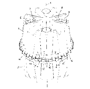
Figure 1 illustrates a perspective view of a con-
tainer;
Figure 2 is a view of a detail of the containershown in Figure 1 in a part.ly coupled state, and illustrated
on an enlarged scale;
Figure 3 is a schematic illustration of a cut-out
of both shells, in a position in which they can not be cou-
pled together;
Figure 4 is a illustration similar to Figure 3,
but in a position of the two shells in which they can be cou-
pled together;
3() Figure 5 is a section along line V-V of Figure 1,
without any wedge clamp; and
Figure 6 is a schematic view of a wedge clamp.

CA 02234378 1998-04-06
DETAILED DESCRIPTION OF A PREFERRED EMBODIMENT
The container is illustrated in Figure 1 in its
.5 operat:ional position according to which the longitudinal axis
1 extends vertically. The container has a lower shell 2 and
an upper shell 3. The lower shell 2 has an upper port edge 4
and the upper shell 3 has a lower port edge 5. The two shells
2 and 3 face each other at their port edges 4 and 5 and abut
each other by these port edges 4 and 5 via not illustrated
sealing means (Figures 1, 5).
The two shells 2 and 3 consist of a plastic m.ate-
rial and are produced by injection molding. As a plastic ma-
terial. High Density Polyethylene (HDPE) and also Polypropyl-
1.5 ene-Cc,polymeres (PPC) have been proven to be useful. At t.he
exampl.e illustrated in Figure 1 the upper shell 3 is equi.pped
with connecting stubs 6-9 for conduits. The lower shell 3 may
be equipped with the same connection stubs which, however,
are nc,t illustrated. Because the container commonly serves
for a receiving of rain water as water tank the two shells 2
and 3 must be able to be coupled together in a water tight
manner. As is common, the not illustrated sealing means are
placecL into a space 10 between the two port edges 4 and 5.
The shell port edge 5 of the upper shell 3 in-
cludes a plurality of semi-wedges 11,12 arranged distributed
along its circumference. The shell port edge 4 of the lower
shell 2 includes identical semi-wedges 11' and 12'. The semi-
wedges 11' and 12' which are arranged distributed along the
shell port edge 4 alternate with regard to their direction of
inclin.e, so that the direction of tightening of the wedges
extend.s once in one circumferential direction and then in the
opposite circumferential direction. This can be seen in E'ig-
ures 1-4. The same is true for the semi-wedges 11 and 12 ar-

CA 02234378 1998-04-06
rangecl distributed along the circumference of the shell E)ort
edge 5 alternate with regard to the direction of their incli-
nation. By this important measure it has become possible that
the lower shell 2 and the upper shell 3 are of an identic:al
design such as will be explained further below. As can be
seen in Figures 1 and 2, each port edges 4 and 5 extends cir-
cularly along the circumference of the shell, with the center
coinciding with the longitudinal axis 1. As illustrated i.n
Figures 1, 2 and 5, the semi-wedges 11,12 of the shell 3 are
arranqed on a flange 13 and are, therefore, located due t:o
this flange in a radial direction outside of the rest of the
wall 14 of the shell. In the same manner the semi-wedges 11'
and 12' of the shell 2 are arranged on a flange 13' and are,
theref.-ore, located due to this flange in a radial directi.on
outsicle of the rest of the wall 14' ofd the shell (Figure 5).
At the area of the flanges 13, 13' the shells 2 and 3 are
provicled with stiffening ribs 15, 15'.
The procedure of assembling the two shells 2 and
3 to a complete container proceeds as follows. When both
2~ shells 2 and 3 are of a identical design they thus can be
produc:ed on one and the same injection molding tool; are,
theref.ore, two bodies ejected in succession out of the injec-
tion molding machine. If now these two identical shells 2, 3
are brought together such that they contact each other at.
2.5 their port edges 4,5, the semi-wedges 11,11' and 12,12' which
are iclentical can be positioned opposite of each other as
shown in Figure 3. In this position the two identical shells
2 and 3 can not be coupled together; a rotating in the direc-
tion of the double arrow A in Figure 3 by one division of the
semi-wedges arranged distributed along the circumference is
necessary in order to reach the position according to Figure
4. In Figure 4, now, the semi-wedges 11', 12 and 11, 12', re-
specti.vely are located opposite of each other and form a com-

CA 02234378 1998-04-06
plete wedge 11', 12 or 11, 12', respectively In this position
accorcling to Figure 4 the two shells 2 and 3 can now be cou-
pled together. This is performed by separate wedge clamps ]6
which also consist advantageously of a plastic material. Now,
5 such a wedge clamp 16 can be slid over each complete wedge
11', 12 or 11, 12', wherewith the two semi-wedges 11', 12 or
11, 12', respectively are pressed together, so that accord-
ingly the two shells 2 and 3 are pressed together at their
port edges 4 and 5. Thus, every wedge clamp 16 is seated with
a wedge effect on a complete wedge 11', 12 or 11, 12' and
grips around the semi-wedges 11' and 12 or 12' and 11, re-
spectively. In order to be able to grip around the wedge
clamp 16 is provided with webs 17 and 18 (Figure 6). In E'ig-
ure 2 two wedge clamps 16 are illustrated before they are
driver-, in the direction of the arrows B and C onto the com-
plete wedges 11', 12 and 11, 12', respectively. One wedge
clamp 16 is already in its final mounted state. As can be
seen in the Figures 1 and 2, the mounted wedge clamps 16 are
located on a annular path having its center coinciding with
the lc,ngitudinal axis 1.
Because the direction of the incline of the semi-
wedges arranged distributed along the circumference of the
shell port edge in a staggered manner alternate, a large ad-
vantage is reached in that the two shells of the container
can be of an identical design, thus that they are accordingly
two same injection molding products. This means that only one
single injection molding tool is needed.
While these is shown and described a present pre-
ferrecL embodiment of the invention it is to be distinctly un-
derstood that the invention is not limited thereto, but maybe otherwise variously embodied and practiced within the
scope of the following claims.

Dessin représentatif
Une figure unique qui représente un dessin illustrant l'invention.
États administratifs

2024-08-01 : Dans le cadre de la transition vers les Brevets de nouvelle génération (BNG), la base de données sur les brevets canadiens (BDBC) contient désormais un Historique d'événement plus détaillé, qui reproduit le Journal des événements de notre nouvelle solution interne.

Veuillez noter que les événements débutant par « Inactive : » se réfèrent à des événements qui ne sont plus utilisés dans notre nouvelle solution interne.

Pour une meilleure compréhension de l'état de la demande ou brevet qui figure sur cette page, la rubrique Mise en garde , et les descriptions de Brevet , Historique d'événement , Taxes périodiques et Historique des paiements devraient être consultées.

Historique d'événement

Description Date
Inactive : CIB de MCD 2006-03-12
Demande non rétablie avant l'échéance 2004-04-06
Le délai pour l'annulation est expiré 2004-04-06
Réputée abandonnée - omission de répondre à un avis sur les taxes pour le maintien en état 2003-04-07
Inactive : Abandon.-RE+surtaxe impayées-Corr envoyée 2003-04-07
Réputée abandonnée - omission de répondre à un avis exigeant une traduction 1999-11-17
Inactive : Supprimer l'abandon 1999-05-04
Inactive : Correspondance - Formalités 1998-11-30
Inactive : Incomplète 1998-11-17
Demande publiée (accessible au public) 1998-10-11
Inactive : CIB attribuée 1998-07-30
Inactive : CIB enlevée 1998-07-30
Inactive : CIB en 1re position 1998-07-30
Symbole de classement modifié 1998-07-30
Inactive : CIB en 1re position 1998-07-30
Inactive : CIB attribuée 1998-07-30
Modification reçue - modification volontaire 1998-07-06
Inactive : Certificat de dépôt - Sans RE (Anglais) 1998-06-17
Exigences de dépôt - jugé conforme 1998-06-17
Demande reçue - nationale ordinaire 1998-06-16

Historique d'abandonnement

Date d'abandonnement Raison Date de rétablissement
2003-04-07
1999-11-17

Taxes périodiques

Le dernier paiement a été reçu le 2002-02-18

Avis : Si le paiement en totalité n'a pas été reçu au plus tard à la date indiquée, une taxe supplémentaire peut être imposée, soit une des taxes suivantes :

  • taxe de rétablissement ;
  • taxe pour paiement en souffrance ; ou
  • taxe additionnelle pour le renversement d'une péremption réputée.

Veuillez vous référer à la page web des taxes sur les brevets de l'OPIC pour voir tous les montants actuels des taxes.

Historique des taxes

Type de taxes Anniversaire Échéance Date payée
Taxe pour le dépôt - générale 1998-04-06
TM (demande, 2e anniv.) - générale 02 2000-04-06 2000-03-16
TM (demande, 3e anniv.) - générale 03 2001-04-06 2001-03-02
TM (demande, 4e anniv.) - générale 04 2002-04-08 2002-02-18
Titulaires au dossier

Les titulaires actuels et antérieures au dossier sont affichés en ordre alphabétique.

Titulaires actuels au dossier
OTTO PETER GRAF
Titulaires antérieures au dossier
S.O.
Les propriétaires antérieurs qui ne figurent pas dans la liste des « Propriétaires au dossier » apparaîtront dans d'autres documents au dossier.
Documents

Pour visionner les fichiers sélectionnés, entrer le code reCAPTCHA :


Pour visualiser une image, cliquer sur un lien dans la colonne description du document. Pour télécharger l'image (les images), cliquer l'une ou plusieurs cases à cocher dans la première colonne et ensuite cliquer sur le bouton "Télécharger sélection en format PDF (archive Zip)" ou le bouton "Télécharger sélection (en un fichier PDF fusionné)".

Liste des documents de brevet publiés et non publiés sur la BDBC .

Si vous avez des difficultés à accéder au contenu, veuillez communiquer avec le Centre de services à la clientèle au 1-866-997-1936, ou envoyer un courriel au Centre de service à la clientèle de l'OPIC.


Description du
Document 
Date
(aaaa-mm-jj) 
Nombre de pages   Taille de l'image (Ko) 
Dessin représentatif 1998-10-09 1 20
Page couverture 1998-10-09 1 52
Dessins 1998-07-06 3 86
Description 1998-04-06 6 248
Abrégé 1998-04-06 1 16
Revendications 1998-04-06 2 66
Dessins 1998-04-06 3 98
Certificat de dépôt (anglais) 1998-06-17 1 163
Rappel de taxe de maintien due 1999-12-07 1 111
Rappel - requête d'examen 2002-12-09 1 113
Courtoisie - Lettre d'abandon (taxe de maintien en état) 2003-05-05 1 176
Courtoisie - Lettre d'abandon (requête d'examen) 2003-06-16 1 165
Correspondance 1998-06-17 2 71
Correspondance 1998-11-12 1 10