Sélection de la langue

Search

Sommaire du brevet 2235544 

Énoncé de désistement de responsabilité concernant l'information provenant de tiers

Une partie des informations de ce site Web a été fournie par des sources externes. Le gouvernement du Canada n'assume aucune responsabilité concernant la précision, l'actualité ou la fiabilité des informations fournies par les sources externes. Les utilisateurs qui désirent employer cette information devraient consulter directement la source des informations. Le contenu fourni par les sources externes n'est pas assujetti aux exigences sur les langues officielles, la protection des renseignements personnels et l'accessibilité.

Disponibilité de l'Abrégé et des Revendications

L'apparition de différences dans le texte et l'image des Revendications et de l'Abrégé dépend du moment auquel le document est publié. Les textes des Revendications et de l'Abrégé sont affichés :

  • lorsque la demande peut être examinée par le public;
  • lorsque le brevet est émis (délivrance).
(12) Brevet: (11) CA 2235544
(54) Titre français: PAIRE D'ORGANES RAFFINEURS DESTINES A UNE RAFFINEUSE A DISQUES
(54) Titre anglais: A PAIR OF CO-OPERATING REFINING ELEMENTS INTENDED FOR A DISC REFINER
Statut: Durée expirée - au-delà du délai suivant l'octroi
Données bibliographiques
(51) Classification internationale des brevets (CIB):
  • D21D 01/30 (2006.01)
  • B02C 07/12 (2006.01)
(72) Inventeurs :
  • KJELLQVIST, OLOF (Suède)
  • NASTREN, CHRISTER (Suède)
(73) Titulaires :
  • VALMET FIBERTECH AKTIEBOLAG
(71) Demandeurs :
  • VALMET FIBERTECH AKTIEBOLAG (Suède)
(74) Agent: SMART & BIGGAR LP
(74) Co-agent:
(45) Délivré: 2004-03-30
(86) Date de dépôt PCT: 1996-10-09
(87) Mise à la disponibilité du public: 1997-05-22
Requête d'examen: 2001-08-14
Licence disponible: S.O.
Cédé au domaine public: S.O.
(25) Langue des documents déposés: Anglais

Traité de coopération en matière de brevets (PCT): Oui
(86) Numéro de la demande PCT: PCT/SE1996/001274
(87) Numéro de publication internationale PCT: SE1996001274
(85) Entrée nationale: 1998-04-22

(30) Données de priorité de la demande:
Numéro de la demande Pays / territoire Date
9504023-4 (Suède) 1995-11-13

Abrégés

Abrégé français

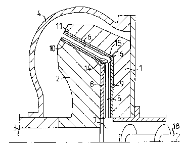
L'invention porte sur une paire d'organes raffineurs (10, 11) fonctionnant de concert destinés à une raffineuse à disques permettant de désagréger finement et de raffiner un matériau lignocellulosique en forme de bloc dans un passage de raffinage (5, 6) entre deux disques raffineurs opposés (1, 2). La partie extérieure (6) du passage de raffinage forme un angle par rapport au plan radial et le disque raffineur (2) situé en dehors de la partie extérieure (6) du passage de raffinage est rotatif. Les organes raffineurs (10, 11) sont conçus pour se placer juste en face l'un de l'autre sur des disques raffineurs opposés, dans cette partie extérieure (6) du passage de raffinage. L'organe raffineur (10) situé à l'intérieur est pourvu d'au moins une aile (14) saillant librement en direction de la partie intérieure (5) du passage de raffinage. L'organe raffineur (11) situé en dehors comporte une section d'entrée (15) se trouvant juste en face de l'aile (14) pourvue d'une face courbe concave (16). Cette aile a pour but de projeter le matériau contre la face recourbée (16) afin de modifier le sens de déplacement du matériau dans la partie angulaire extérieure (6) du passage de raffinage.


Abrégé anglais


A pair of co-operating refining
elements (10, 11) intended for
a disc refiner for finely disintegrating
and refining lump-shaped lignocellulosic
material in a refiner gap
(5, 6) between two opposed refining
discs (1, 2). The outer portion (6) of
the refiner gap is angular in relation
to the radial plane, and the refining
disc (2) located outside the outer
portion (6) of the refiner gap is
rotary. The refining elements (10, 11)
are intented to be placed directly
in front of each other on opposed
refining discs in this outer portion
(6) of the refiner gap. The refining
element (10) located inside is
provided with at least one wing (14)
freely projecting in the direction to
the inner portion (5) of the refiner
gap. The refining element (11) located
outside has an inlet portion
(15) located directly in front of the
wing (14) which is formed with a
concavely curved surface (16). The
wing is provided to throw the material against the curved surface (16) for
changing the direction of movement of the material into the outer
angular portion (6) of the refiner gap.

Revendications

Note : Les revendications sont présentées dans la langue officielle dans laquelle elles ont été soumises.


5
Claims
1. A pair of co-operating refining elements (10,11) intended for
a disc refiner for finely disintegrating and refining lump-shaped
lignocellulosic material in a refiner gap (5,6) between two opposed
refining discs (1,2) where the outer portion (6) of the refiner gap
is angular in relation to the radial plane, and the refiner disc
(1) located outside the outer portion (6) of the refiner gap is stat-
ionary, and the refining disc (2) located inside is rotary, and the
refining elements (10,11) are intended to be placed directly in front
of each other on opposed refining discs in this outer portion (6)
of the refiner gap, characterized in that the re-
fining element (10) located inside is provided with at least one
wing (14) freely projecting in the direction to the inner portion
(5) of the refiner gap, and that the refining element (11) located
outside has an inlet portion (15) located directly in front of the
wing (14), which inlet portion is formed with a concavely curved
surface (16), and the wing (14) is provided to throw the material
against the curved surface (16) for changing the direction of move-
ment of the material into the outer angular portion of the refiner
gap.
2. Refining elements as defined in claim 1, character-
ized in that each wing (14) is curved to the inner portion
(5) of the refiner gap.
3. Refining elements as defined in claim 1 or 2, charact-
erized in that the concavely curved surface (16) parti-
ally encloses the wing (14), the upper edge of which has a curvat-
ure substantially corresponding to the curvature of the curved surf-
ace (16).
4. Refining elements as defined in claim 1 or 2, charact-
erized in that the inlet portion on the refining elements
(11) located outside is provided with a shoulder (17) with inclined
flanks.

Description

Note : Les descriptions sont présentées dans la langue officielle dans laquelle elles ont été soumises.


CA 02235544 1998-04-22
WO 97/18037 PCT/SE96/01274
A PAIR OF CO-OPERATING REFINING ELEMENTS INTENDED FOR A DISC REFINER
This invention relates to refining elements for use in refiners of
disc type for lump-shaped, preferably lignocellulosic material, of
which refiner the refining means rotary relative to each other
are provided with refining elements, which form a refiner gap
between themselves. The outer portion of the refiner gap, spaced
from the rotation centre, is angular in relation to the radial plane,
so that it extends to a substantial degree in axial direction.
A particularly important field of application far the invention are
refiners for making fiber- or papermaking pulp from wood chips or
similar cellulosic material. Refiners of disc type are formed with
a refiner gap extending in radial direction between the refining
elements of the refining means, which gap starts from a central feed
zone for the raw material where the centrifugal force is relatively
low. The centrifugal force affecting the material to be refined in-
creases then very strongly with increasing radius. In order to pro-
long the staytime in the outer portion of the refiner gap, the re-
finer gap in its outer portion can be formed so as to extend angul-
arly in relation to the radial direction, so that only part of the
centrifugal force is allowed to affect the material to be refined
in the flow direction of the refiner gap. While, thus, steps have
been taken in the radially outer portion of the refiner gap in order
to limit the flow rate of the material to be refined in this outer
portion, it applies also to this design that the effect of the cen-
trifugal force in the central feed zone is low, so that the feed
to the outer angular portion of the refiner gap is not as intensive
as would be desired in order to achieve maximum capacity of the re-
finer. Attempts have been made to introduce mechanical devices to
promote the discharge in the central feed zone, which, however, are
not effective, because a.o. they must be exchanged relatively often
due to their rapid wear.

CA 02235544 2003-12-15
28229-92
2
The invention has the object to eliminate these
problems and thereby bring about an effective feed of the
material to be refined from the inner radial portion of the
refining zone to the outer angular portion. This is
achieved in that the refiner elements in the outer angular
portion of the refining zone are designed so as defined in
the attached claims.
According to the present invention, there is
provided a pair of co-operating refining elements (10, 11)
intended for a disc refiner for finely disintegrating and
refining lump-shaped lignocellulosic material in a refiner
gap (5, 6) between two opposed refining discs (1, 2) where
the outer portion (6) of the refiner gap is angular in
relation to the radial plane, and the refiner disc (1)
located outside the outer portion (6) of the refiner gap is
stationary, and the refining disc (2) located inside is
rotary, and the refining elements (10, 11) are intended to
be placed directly in front of each other on opposed
refining discs in this outer portion (6) of the refiner gap,
characterized in that the refining element (10) located
inside is provided with at least one wing (14) freely
projecting in the direction to the inner portion (5) of the
refiner gap, and that the refining element (11) located
outside has an inlet portion (15) located directly in front
of the wing (14), which inlet portion is formed with a
concavely curved surface (16), and the wing (14) is provided
to throw the material against the curved surface (16) for
changing the direction of movement of the material into the
outer angular portion of the refiner gap.

CA 02235544 2003-12-15
28229-92
2a
By forming the co-operating refining elements with wings and, res-
pectively, concavely curved surface, feed from the inner portion
of the refining zone to the angular outer portion is ensured. The
wings on the rotating refining elements, thus, throw the material
to be refined against the concavely curved surface of the stationary
refining elements, so that the material to be refined is caused to
change its direction into the angular portion of the refiner gap.
By this arrangement both the capacity and the load can be increased
substantially, and thereby also the energy consumption at the refin-
ing is reduced by 5-10% to the same pulp quality.
The invention is described in greater detail in the following, with
reference to the accompanying drawings illustrating embodiments of
the invention.
Fig. 1 shows schematically a refiner with an inner radial and an
outer angular refiner gap portion,
Fig. 2 shows on an enlarged scale the two co-operating refining
elements in the outer portion of the refiner gap in Fig. 1,
Figs. 3 and 4 show an alternative embodiment of a refining element
for the rotary refining disc located inside the angular portion of
the refiner gap,
Figs. 5 and 6 show an alternative embodiment of a refining element
for the stationary refining disc located outside the angular portion
of the refiner gap.
The refiner shown in Fig. 1 is formed with a stationary refining
disc 1 and a rotary refining disc 2 mounted on a rotary shaft 3.

CA 02235544 1998-04-22
WO 97/18037 PCT/SE96/01274
3
The refiner gap can be controlled by axial movement of the shaft 3.
The refining discs are enclosed in an airtight refiner housing 4.
Between the refining discs a refiner gap is formed, which consists
of an inner radial portion 5 and an angular outer portion 6. The
inclination angle to the rotary shaft should be less than 45°, pref-
erably between 10 and 30°. The stationary refining disc 1 has a cen-
tral opening 7, through which the material to be refined is fed.
Each of the refining discs is provided with wear portions in the
form of refining elements 8-11 both in the inner radial portion of
the refiner gap 5 and in the outer angular portion 6. The refining
elements are provided with bars 12 and intermediate grooves 13 for
working aE~~l refiningv the material to be refined.
In the outer angular portion 6 of the refiner gap, the stationary
refining disc 1 is located outside the rotary refining disc 2. The
refining elements 10,11 on these refining discs 1,2, thus, are
located outside the outer angular portion of the refiner gap.
The refining element: 10 located inside:is provided with at least
one freely projecting wing 14 extending in the direction to the
inner radial portion 5 if the refiner gap. Each wing 14 preferably
is formed as an extension of one of the bars 12 °n the refining
element 10. The bars 12 can also be angular in relation to the
radius, in order to increase the pumping effect. The wing, like
the bars, is widest at the base and tapers upward. It can also be
curved to the inner portion 5 of the refiner gap. According to the
embodiment shown, the refining element 10 is provided with two
wings 14. The refining element 11 located outside is provided
with an inlet portion 15 located directly in front of the wings 14
and provided with a concavely curved surface 16. The inlet portion
15 can. be curved to the inner portion 5 of the refiner gap, so
that it partially encloses the wings 14. The upper edge of the
wings 14 can have a curvature, which substantially corresponds to
the curvature of the inlet portion 15, as shown in Fig. 2.

CA 02235544 1998-04-22
WO 97f18037 PCT/SE96/01274
4
Owing to its design and the rotation of the refining disc 2, the
wings 14 on the refining element 10 located inside throw the material
to be refined obliquely outward to the inlet portion 15 on the re-
fining element 11 located outside. When the material to be refined
meets the concavely curved surface 16, the direction of movement
of the material to be refined is changed into the outer angular port-
ion 6 of the refiner gap.
According to the embodiments of the two co-operating refining ele-
ments shown in Figs. 3-6, the refining element 10 located inside is
formed with projecting wings 14, as at the embodiment according to
Figs. 1 and 2. The refining element 11 located outside, however, has
been completed with a shoulder 17 in the concavely curved surface 16
in the inlet portion 15. The shoulder 17 preferably has a substant-
ially triangular cross-section. The inclined flanks on the shoulder
17 are intended to additionally improve the feed of the material to
be refined into the outer angular portion 6 of the refiner gap,
The material to be refined is fed into the central feed zone between
the refining discs through the opening 7 in the stationary refining
disc 1 by means of a feed screw 18 coaxial with the shaft 3. The
material to be refined is thereby caused to move outward through the
inner radial portion 5 of the refiner gap while simultaneously being
worked by the radial refining elements 8-9. The feed from the inner
radial portion 5 of the refiner gap to the outer angular portion 6
is promoted by the wings l4and opposite inlet portion 15. It was,
thus, found that both the capacity and load could be increased con-
siderably, by about 20%, by using this type of refining elements,
compared with conventional ones. It also was found that it is~_poss-
ible to reduce the specific energy consumption by 5-10%. It should
be noted, too, that these improvements were achieved with maintained
pulp quality.
The invention, of course, is not restricted to the embodiments shown,
but can be varied within the scope of the invention idea.

Dessin représentatif
Une figure unique qui représente un dessin illustrant l'invention.
États administratifs

2024-08-01 : Dans le cadre de la transition vers les Brevets de nouvelle génération (BNG), la base de données sur les brevets canadiens (BDBC) contient désormais un Historique d'événement plus détaillé, qui reproduit le Journal des événements de notre nouvelle solution interne.

Veuillez noter que les événements débutant par « Inactive : » se réfèrent à des événements qui ne sont plus utilisés dans notre nouvelle solution interne.

Pour une meilleure compréhension de l'état de la demande ou brevet qui figure sur cette page, la rubrique Mise en garde , et les descriptions de Brevet , Historique d'événement , Taxes périodiques et Historique des paiements devraient être consultées.

Historique d'événement

Description Date
Inactive : Périmé (brevet - nouvelle loi) 2016-10-09
Inactive : Lettre officielle 2010-02-26
Inactive : Lettre officielle 2010-02-24
Inactive : Paiement - Taxe insuffisante 2009-12-04
Inactive : Renversement de l'état sera réputé périmé 2009-12-04
Lettre envoyée 2009-10-09
Inactive : CIB de MCD 2006-03-12
Accordé par délivrance 2004-03-30
Inactive : Page couverture publiée 2004-03-29
Inactive : Taxe finale reçue 2003-12-30
Préoctroi 2003-12-30
Exigences de modification après acceptation - jugée conforme 2003-12-23
Lettre envoyée 2003-12-23
Inactive : Taxe de modif. après accept. traitée 2003-12-15
Modification après acceptation reçue 2003-12-15
Lettre envoyée 2003-12-02
Un avis d'acceptation est envoyé 2003-12-02
Inactive : Approuvée aux fins d'acceptation (AFA) 2003-10-27
Lettre envoyée 2001-09-14
Exigences pour une requête d'examen - jugée conforme 2001-08-14
Toutes les exigences pour l'examen - jugée conforme 2001-08-14
Requête d'examen reçue 2001-08-14
Inactive : Lettre officielle 2000-09-19
Inactive : Transferts multiples 2000-08-21
Symbole de classement modifié 1998-08-21
Inactive : CIB en 1re position 1998-08-21
Inactive : CIB attribuée 1998-08-21
Inactive : Notice - Entrée phase nat. - Pas de RE 1998-07-03
Demande reçue - PCT 1998-07-02
Demande publiée (accessible au public) 1997-05-22

Historique d'abandonnement

Il n'y a pas d'historique d'abandonnement

Taxes périodiques

Le dernier paiement a été reçu le 2003-09-18

Avis : Si le paiement en totalité n'a pas été reçu au plus tard à la date indiquée, une taxe supplémentaire peut être imposée, soit une des taxes suivantes :

  • taxe de rétablissement ;
  • taxe pour paiement en souffrance ; ou
  • taxe additionnelle pour le renversement d'une péremption réputée.

Les taxes sur les brevets sont ajustées au 1er janvier de chaque année. Les montants ci-dessus sont les montants actuels s'ils sont reçus au plus tard le 31 décembre de l'année en cours.
Veuillez vous référer à la page web des taxes sur les brevets de l'OPIC pour voir tous les montants actuels des taxes.

Titulaires au dossier

Les titulaires actuels et antérieures au dossier sont affichés en ordre alphabétique.

Titulaires actuels au dossier
VALMET FIBERTECH AKTIEBOLAG
Titulaires antérieures au dossier
CHRISTER NASTREN
OLOF KJELLQVIST
Les propriétaires antérieurs qui ne figurent pas dans la liste des « Propriétaires au dossier » apparaîtront dans d'autres documents au dossier.
Documents

Pour visionner les fichiers sélectionnés, entrer le code reCAPTCHA :


Pour visualiser une image, cliquer sur un lien dans la colonne description du document. Pour télécharger l'image (les images), cliquer l'une ou plusieurs cases à cocher dans la première colonne et ensuite cliquer sur le bouton "Télécharger sélection en format PDF (archive Zip)" ou le bouton "Télécharger sélection (en un fichier PDF fusionné)".

Liste des documents de brevet publiés et non publiés sur la BDBC .

Si vous avez des difficultés à accéder au contenu, veuillez communiquer avec le Centre de services à la clientèle au 1-866-997-1936, ou envoyer un courriel au Centre de service à la clientèle de l'OPIC.


Description du
Document 
Date
(aaaa-mm-jj) 
Nombre de pages   Taille de l'image (Ko) 
Dessin représentatif 1998-08-25 1 12
Dessin représentatif 2003-10-28 1 13
Description 2003-12-14 5 214
Abrégé 1998-04-21 1 59
Description 1998-04-21 4 178
Revendications 1998-04-21 1 40
Dessins 1998-04-21 2 68
Avis d'entree dans la phase nationale 1998-07-02 1 209
Courtoisie - Certificat d'enregistrement (document(s) connexe(s)) 1998-07-02 1 140
Rappel - requête d'examen 2001-06-11 1 118
Accusé de réception de la requête d'examen 2001-09-13 1 194
Avis du commissaire - Demande jugée acceptable 2003-12-01 1 160
Avis de paiement insuffisant pour taxe (anglais) 2009-12-03 1 91
PCT 1998-04-21 7 254
Correspondance 2000-09-18 1 19
Taxes 2003-09-17 1 35
Correspondance 2003-12-29 1 33
Taxes 2000-09-12 1 40
Taxes 2009-09-23 1 42
Correspondance 2009-12-03 1 23
Taxes 2009-12-15 4 148
Correspondance 2010-02-23 2 33
Correspondance 2010-02-25 1 14