Sélection de la langue

Search

Sommaire du brevet 2236051 

Énoncé de désistement de responsabilité concernant l'information provenant de tiers

Une partie des informations de ce site Web a été fournie par des sources externes. Le gouvernement du Canada n'assume aucune responsabilité concernant la précision, l'actualité ou la fiabilité des informations fournies par les sources externes. Les utilisateurs qui désirent employer cette information devraient consulter directement la source des informations. Le contenu fourni par les sources externes n'est pas assujetti aux exigences sur les langues officielles, la protection des renseignements personnels et l'accessibilité.

Disponibilité de l'Abrégé et des Revendications

L'apparition de différences dans le texte et l'image des Revendications et de l'Abrégé dépend du moment auquel le document est publié. Les textes des Revendications et de l'Abrégé sont affichés :

  • lorsque la demande peut être examinée par le public;
  • lorsque le brevet est émis (délivrance).
(12) Demande de brevet: (11) CA 2236051
(54) Titre français: RECIPIENT
(54) Titre anglais: CONTAINER
Statut: Réputée abandonnée et au-delà du délai pour le rétablissement - en attente de la réponse à l’avis de communication rejetée
Données bibliographiques
(51) Classification internationale des brevets (CIB):
  • B65D 43/14 (2006.01)
  • B65D 21/06 (2006.01)
  • B65D 25/30 (2006.01)
  • B65D 43/02 (2006.01)
(72) Inventeurs :
  • COPE, ANDREW CHRISTOPHER (Royaume-Uni)
(73) Titulaires :
  • MCKECHNIE UK LIMITED
(71) Demandeurs :
  • MCKECHNIE UK LIMITED (Royaume-Uni)
(74) Agent: RICHES, MCKENZIE & HERBERT LLP
(74) Co-agent:
(45) Délivré:
(22) Date de dépôt: 1998-04-27
(41) Mise à la disponibilité du public: 1998-10-29
Licence disponible: S.O.
Cédé au domaine public: S.O.
(25) Langue des documents déposés: Anglais

Traité de coopération en matière de brevets (PCT): Non

(30) Données de priorité de la demande:
Numéro de la demande Pays / territoire Date
9708741.5 (Royaume-Uni) 1997-04-29

Abrégés

Abrégé français

Un couvercle de récipient 12 a une partie de sécurité 36 rattachée à une ligne d'articulation 38 de sorte que, lorsque le couvercle est mis en place, la partie 36 peut descendre à l'intérieur du récipient pour obstruer une ouverture dans la paroi du récipient de manière à améliorer la sécurité. Des rebords 44 appuient sur le dessous du couvercle 12B pour empêcher la partie de sécurité 36 d'être écartée de l'ouverture obstruée. Le couvercle est décrit comme faisant partie d'un récipient dont le corps peut s'emboîter dans celui d'un récipient semblable dont le couvercle est enlevé et logé à l'intérieur du récipient quand celui-ci n'est pas utilisé.


Abrégé anglais


A container lid 12 has a security portion 36 attached at a hinge line 38 so
that as the lid is closed, the portion 36 can hang down inside the container to
obstruct an aperture in a wall of the container, thereby improving security.
Flanges 44 abut the underside of the lid 12B to prevent the security portion 36
being pushed away from the aperture being obstructed. The lid is described as
part of a container whose body can nest with a body of a like container, with the
lid removed and housed within the container, when not in use.

Revendications

Note : Les revendications sont présentées dans la langue officielle dans laquelle elles ont été soumises.


CLAIMS
1. A container lid comprising a main lid portion and a security portion
which, in use, obstructs an aperture in a wall of a container to which the lid is
fitted.
2. A lid according to claim 1, wherein the security portion substantially
blocks the aperture.
3. A lid according to claim 1 or 2, wherein the security portion hangs from
the main lid portion.
4. A lid according to claim 3, wherein the security portion hangs inside the
container.
5. A lid according to any preceding claim, wherein the security portion is
hingedly attached to the main lid portion for movement between an in use
position and a stowed position substantially in the plane of the main lid
portion.
6. A lid according to any preceding claim, wherein abutment means are
provided to prevent the security portion being pushed away from the aperture
when in use.
7. A lid according to any preceding claim, and comprising two main lid
portions hingedly attached.
8. A lid according to claim 7, wherein both main lid portions carry a
security portion as aforesaid.
9. A container having a container lid according to any preceding claim.
10. A container according to claim 9, wherein the container body is nestable

and stackable with a like container body.
11. A container according to claim 10, wherein the lid is formed to be
received within the container while another like container is nested therein.
12. A container according to any of claims 9 to 11, wherein the wall aperture
is a handle.
13. A container according to any of claims 9 to 12, wherein the security
portion is formed to provide a finger grip through the aperture.
14. A container according to any of claims 9 to 13 and further comprising
lock means operable to lock the lid to the container while the security portion is
obstructing the aperture.

Description

Note : Les descriptions sont présentées dans la langue officielle dans laquelle elles ont été soumises.

CA 022360~1 1998-04-27
Container
The present invention relates to containers and particularly, but not
exclusively, to stackable/nestable containers for delivery of goods to retail
premises.
Containers for use in delivering goods to retail premises are required in
some instances to be reasonably secure against pilfering, particularly if used for
relatively small, high value goods, such as perfllme.
The present invention provides a container lid comprising a main lid
portion and security portion which, in use, obstructs an aperture in a wall of acontainer to which the lid is fitted.
Preferably the security portion substantially blocks the aperture. The
security portion preferably hangs from the main lid portion, and preferably
hangs inside the container. The security portion may be hingedly attached to
the main lid portion for movement between an in use position and a stowed
position substantially in the plane of the main lid portion.
Preferably abutment means are provided to prevent the security portion
being pushed away from the aperture when in use.
The lid may comprise two main lid portions hingedly attached, both of
which may carry a security portion as aforesaid.
The invention also provides a container having a container lid as
aforesaid.
Preferably the container body is nestable and stackable with a like
container body and preferably the lid is formed to be received within the
container while another like container is nested therein.

CA 022360~1 1998-04-27
The wall aperture may be a handle. The security portion may be formed
to provide a finger grip through the aperture.
One embodiment of the present invention will now be described in more
detail, by way of example only, and with reference to the accompanying
drawings, in which:
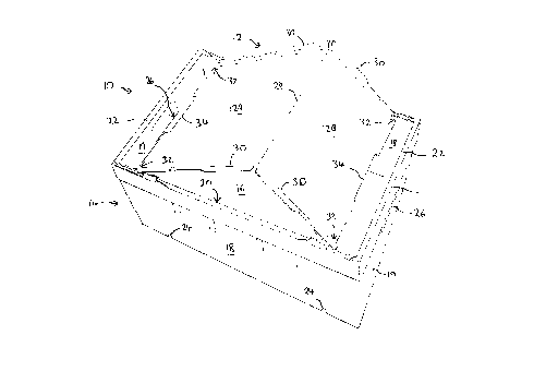
Fig. 1 is a schematic perspective view of a container to which a lid
according to the present invention is being fitted;
Fig. 2 shows the container and lid of Fig. 1, with the lid ~lmost fully
closed;
Fig. 3 shows the container of Figs. 1 and 2 with the lid fully closed and
the container in condition for stacking;
Figs. 4A and 4B are enlarged perspective views of one edge of the lid,
showing the security portion of the lid; and
Fig. 5 is a highly schematic vertical section, on a much reduced scale,
through two containers stacked for return.
Fig. 1 shows a container 10 having a lid 12 and main body 14. The
container 10 has a base 16, side walls 18 and end walls 19, the walls being
upstanding from the base 16 to define an upper container mouth 20. The walls
18,19 are inclined slightly in known manner to allow the main body 14 to nest
within a like body located beneath, or to allow another like body to nest withinfrom above. In addition, the body 14 is fitted with stacking bars 22 which can
swing from the stowed position (Fig. 1) clear of the mouth 20, to a stacking
position (Fig. 3) overlying the mouth, to provide support for the base of a
container above. Channels are formed in the base of the body 14 (only the ends
24 of the channels being visible in Fig. 1). These channels sit on the bars 22
when containers are stacked. Apertures 26 are formed in walls 18 to provide

CA 022360~1 1998-04-27
handles for lifting the container 10.
The lid 12 has two main lid portions 12A,12B which are generally planar
and hinged to each other at 28. Conveniently, the hinge 28 may be a live hinge
if the lid 12 is formed from a synthetic plastics material, such as by injectionmoulding. The lid 12 also has rims 30 formed along its edges, to support the
lid 12 on the upper edges of the walls 18,19.
The lid 12 can be fitted to the container 10 in the manner illustrated in
the sequence of drawings Figs. 1, 2 and 3. Initially, with the lid portions
12A,12B hinged out of the plane of each other (Fig. 1) the lid 12 is offered to the
container and rests on the walls 18 at the four corners 32 of the lid 12.
As the hinge 28 is lowered, the corners 32 slide along the walls 18 toward
the corners of the mouth 20 and as they do so, the edges 34 of the lid 12 (the
edges parallel to the hinge 28) move toward the end walls 19. Fig. 2 shows the
lid almost fully closed. The mouth 20 is almost fully obstructed, the hinge 28
has been lowered almost to the level of the top of the walls 18 and the edges 34are almost at the end walls 19.
Fig. 3 shows the fully closed position. The rims 30 are resting along the
walls 18 along the whole length of the lid 12. The edges 34 have reached the
end walls 19. The stacking bars 22 have moved to their stacking position
overlying the mouth 20 of the container, and also overlying the lid 12, so that
the weight of a container stacked above will be borne on the bars 22, not on thelid 12.
Security aspects of the lid arrangement just described can now be
explained with reference to Figs.4A and 4B.
Fig. 4A shows the edge 34 of one of the lid portions 12B. A security
portion 36 is attached at a hinge line 38, allowing the portion 36 to swing
between the position shown in Fig. 4A, in which the portion 36 is generally in or

CA 022360~1 1998-04-27
aligned with the plane of the lid portion 12B, and a second position (Fig. 4B) in
which the portion 36 is generally perpendicular to the lid portion 12B. The
hinge 38 may be a further live hinge.
The portion 36 is generally rectangular and may conveniently be deep
enough to allow a depression 40 to be formed in the front face 42 of the portion36. Flanges 44 are formed on the rear of the portion 36. The ends of the
flanges 44 come into contact with the bottom face of the lid portion 12B when
the portion 36 is hanging down from the lid portion, and prevent the portion 36
moving past the position shown in Fig. 4B.
It will be apparent that by virtue of the hinge 38, the portion 36 would
not normally stay in the position of Fig. 4A unless supported; it would tend to
hang down to a position intermediate that position and the position of Fig. 4B,
according to the angle of the lid 12B to the horizontal.
Accordingly it can be understood from the above description that as the
lid is placed onto the container and closed as described above, the portion 36
will initially hang down inside the container and move toward the end walls 19
as the lid is closed. The portion 36 is shaped to ensure that when the lid 12
reaches its fully closed position (Fig. 3) the portion 36 has moved behind the
handle apertures 26, to obstruct those apertures. Preferably, the portions 36
are sufficiently large to fully close the apertures. It is for this reason that the
depressions 40 are formed. This allows the container to be lifted by placing
fingers into the depressions 40 through the apertures 26, to provide a handle
function. However, access to the interior of the container, and its contents, isno longer possible through the apertures 26 because they are blocked by the
portions 36. Consequently, although the apertures 26 remain available for use
as handles, pilfering through them is substantially prevented. The portions 36
cannot be pushed into the container, clear of the apertures 26, because of the
engagement of the flanges 44 with the lower face of the lid.
In a preferred arrangement, appropriate apertures are formed at a

CA 022360~1 1998-04-27
convenient position in the lid and main body to allow security tags to be
inserted to seal the lid to the body and thus show if a container has been
tampered with. Other lock arrangements could be provided.
In some container designs, it may not be necessary for the security
portions 36 to be hinged to the lid - they could be fixed in the position of Fig.
4B. However, the provision of hinges 38 allows the lid 12 to be folded more
compactly when removed from the container, such as when the container is
being returned after use. In this stage of use, it is common to nest containers
within each other, for compactness. If the lid 12 is folded in half at the hinge28, it is convenient for the portions 36 to hinge to the position of Fig. 4A, to lie
generally within the plane of the corresponding lid portion 12A,12B so that the
depth of the folded lid portion is not increased.
Two containers nested for return are illustrated in Fig. 5. An upper
container 10A is nested in a lower container 10B to leave a space 46 between thebases 16A,16B. The lid 12 of the lower container is folded in half and stowed inthe space 46. It is expected that with a wide variety of stackable/nestable
containers, there will be sufficient clearance to accommodate a folded lid in this
manner, provided the security portions 36 will hinge as has been described.
However, it may be that in some designs, the security portions will not be
required to hinge. These variations within the scope of the invention can be
made in accordance with the particular design of the container, affected by
factors such as the size of the apertures 26, their depth from the mouth of the
container, the thickness of the security portion 36, the depth of the space 46
and the like.
Many variations and modifications can be made to the apparatus
described above, without departing from the scope of the present invention. In
particular, the shape and form of the container and lid can be varied according
to the requirements for the container. Many different materials can be used for
the components, but it is envisaged that a container of the type described can
readily be manufactured from synthetics plastics material, preferably by

CA 022360~1 1998-04-27
injection moulding. In one example, the container may be 400mm x 600mm in
plan, or 400mm x 300mm in plan, with a height of about 200mm.
Whilst endeavouring in the foregoing specification to draw attention to
those features of the invention believed to be of particular importance it should
be understood that the Applicant claims protection in respect of any patentable
feature or combination of features hereinbefore referred to and/or shown in the
drawings whether or not particular emphasis has been placed thereon.

Dessin représentatif
Une figure unique qui représente un dessin illustrant l'invention.
États administratifs

2024-08-01 : Dans le cadre de la transition vers les Brevets de nouvelle génération (BNG), la base de données sur les brevets canadiens (BDBC) contient désormais un Historique d'événement plus détaillé, qui reproduit le Journal des événements de notre nouvelle solution interne.

Veuillez noter que les événements débutant par « Inactive : » se réfèrent à des événements qui ne sont plus utilisés dans notre nouvelle solution interne.

Pour une meilleure compréhension de l'état de la demande ou brevet qui figure sur cette page, la rubrique Mise en garde , et les descriptions de Brevet , Historique d'événement , Taxes périodiques et Historique des paiements devraient être consultées.

Historique d'événement

Description Date
Inactive : CIB de MCD 2006-03-12
Demande non rétablie avant l'échéance 2002-04-29
Le délai pour l'annulation est expiré 2002-04-29
Réputée abandonnée - omission de répondre à un avis sur les taxes pour le maintien en état 2001-04-27
Demande publiée (accessible au public) 1998-10-29
Modification reçue - modification volontaire 1998-09-04
Inactive : Transfert individuel 1998-09-04
Symbole de classement modifié 1998-08-11
Inactive : CIB en 1re position 1998-08-11
Inactive : CIB attribuée 1998-08-11
Inactive : Lettre de courtoisie - Preuve 1998-07-14
Exigences de dépôt - jugé conforme 1998-07-09
Inactive : Certificat de dépôt - Sans RE (Anglais) 1998-07-09
Demande reçue - nationale ordinaire 1998-07-08

Historique d'abandonnement

Date d'abandonnement Raison Date de rétablissement
2001-04-27

Taxes périodiques

Le dernier paiement a été reçu le 2000-03-28

Avis : Si le paiement en totalité n'a pas été reçu au plus tard à la date indiquée, une taxe supplémentaire peut être imposée, soit une des taxes suivantes :

  • taxe de rétablissement ;
  • taxe pour paiement en souffrance ; ou
  • taxe additionnelle pour le renversement d'une péremption réputée.

Veuillez vous référer à la page web des taxes sur les brevets de l'OPIC pour voir tous les montants actuels des taxes.

Historique des taxes

Type de taxes Anniversaire Échéance Date payée
Enregistrement d'un document 1998-04-27
Taxe pour le dépôt - générale 1998-04-27
TM (demande, 2e anniv.) - générale 02 2000-04-27 2000-03-28
Titulaires au dossier

Les titulaires actuels et antérieures au dossier sont affichés en ordre alphabétique.

Titulaires actuels au dossier
MCKECHNIE UK LIMITED
Titulaires antérieures au dossier
ANDREW CHRISTOPHER COPE
Les propriétaires antérieurs qui ne figurent pas dans la liste des « Propriétaires au dossier » apparaîtront dans d'autres documents au dossier.
Documents

Pour visionner les fichiers sélectionnés, entrer le code reCAPTCHA :


Pour visualiser une image, cliquer sur un lien dans la colonne description du document. Pour télécharger l'image (les images), cliquer l'une ou plusieurs cases à cocher dans la première colonne et ensuite cliquer sur le bouton "Télécharger sélection en format PDF (archive Zip)" ou le bouton "Télécharger sélection (en un fichier PDF fusionné)".

Liste des documents de brevet publiés et non publiés sur la BDBC .

Si vous avez des difficultés à accéder au contenu, veuillez communiquer avec le Centre de services à la clientèle au 1-866-997-1936, ou envoyer un courriel au Centre de service à la clientèle de l'OPIC.


Description du
Document 
Date
(aaaa-mm-jj) 
Nombre de pages   Taille de l'image (Ko) 
Page couverture 1998-11-09 1 43
Description 1998-04-27 6 234
Abrégé 1998-04-27 1 15
Revendications 1998-04-27 2 43
Dessins 1998-04-27 4 78
Dessins 1998-09-04 4 112
Dessin représentatif 1998-11-09 1 11
Certificat de dépôt (anglais) 1998-07-09 1 174
Courtoisie - Certificat d'enregistrement (document(s) connexe(s)) 1998-11-03 1 114
Rappel de taxe de maintien due 1999-12-30 1 113
Courtoisie - Lettre d'abandon (taxe de maintien en état) 2001-05-28 1 182
Correspondance 1998-07-14 1 29
Taxes 2000-03-28 1 38