Note : Les descriptions sont présentées dans la langue officielle dans laquelle elles ont été soumises.
CA 02236947 1998-OS-06
PATENT
FASTENER
Background of the Invention
The present invention relates to a new and improved
fastener for use in retaining vertebrae in a desired
spatial relationship.
Rnown fasteners have been used to retain vertebrae in
a desired spatial relationship. At least one of these
known fasteners has a mounting section with an external
thread convolution which engages bone in a vertebra. This
known fastener has a retaining section which extends
axially outward from the mounting section. An external
thread convolution is provided on the retaining section for
engagement with an internally threaded retaining element,
that is, a nut.
A hexagonal intermediate or head section is provided
between the mounting and retaining sections of the known
fastener. The intermediate section of the known fastener
is engageable by a tool to rotate the fastener relative to
a vertebra. A fastener having this construction is
disclosed in U.S. Patent No. 4,854,311. Other known
fasteners which are used to retain vertebrae in a desired
CA 02236947 2001-07-20
30102-3
spatial relationship are disclosed in U.S. Patents Nos.
5,085,660; 5,257,994; and 5,620,443.
Summary of the Invention
The present invention provides a new and improved
fastener to retain vertebrae in a desired spatial relationship.
The fastener includes a mounting section having an external
thread which engages a vertebra. The fastener has a retaining
section. The retaining section may have a pair of parallel
flats disposed on opposite sides of the retaining section. In
addition, the retaining section may have a drive recess
disposed between the flats at one end of the retaining section.
The drive recess has a plurality of arcuate corner portions
which are offset from a plane containing a longitudinal central
axis of the retaining section and extending perpendicular to
the flats.
An external thread may be provided around the
retaining section to engage an internal thread on a retaining
element. The flats on the retaining section may be spaced
apart by a distance which is at least as great as a root
diameter (minor diameter) of the external thread on the
retaining section.
According to a first broad aspect, the invention
provides a fastener for use in retaining vertebrae in a desired
spatial relationship, said fastener comprising a first section
having first external thread means for engaging a vertebra, a
second section connected with said first section and having a
pair of parallel flats disposed on opposite sides of said
second section, said second section having second external
thread means to engage an internal thread on a retaining
element, said flats being spaced apart by a distance which is
at least as great as a root diameter of said second external
CA 02236947 2001-07-20
30102-3
-2a-
thread means, said second external thread means having a root
diameter which is less than the distance between said flats so
that a root portion of said second external thread means
extends across said flats.
According to another broad aspect, the invention
provides a fastener for use in retaining vertebrae in a desired
spatial relationship, said fastener comprising a first section
having first external thread means for threaded engagement with
a vertebra, a second section connected with said first section
and having a pair of parallel flats disposed on opposite sides
of said second section and a driving recess disposed in one end
of said second section between said flats, said driving recess
having a plurality of arcuate corner portions to receive force
to effect rotation of said fastener relative to a vertebra
engaged by said first section, said arcuate corner portions of
said driving recess being offset from a plane containing a
longitudinal central axis of said second section and extending
perpendicular to said flats, and second external thread means
on said second section to engage an internal thread on a
retaining element, said second external thread means having a
root diameter which is no greater than a minimum distance
between said flats.
Brief Description of the Drawings
The foregoing and other features of the present
invention will become more apparent upon a consideration of the . s
following description taken in connection with the accompanying
drawings; wherein:
CA 02236947 1998-OS-06
-3-
Fig. 1 is a simplified schematic illustration
depicting the manner in which a pair of fasteners
constructed in accordance with the present invention are
connected with a vertebra in a spinal column;
Fig. 2 is an enlarged pictorial illustration of one of
the fasteners of Fig. 1;
Fig. 3 is an enlarged fragmentary view of the fastener
of Fig. 2;
Fig. 4 is an end view, taken generally along the line
4-4 of Fig. 3, illustrating the construction of a retaining
section and an intermediate section of the fastener of
Fig. 2;
Fig. 5 is a fragmentary side elevational view, taken
generally along the line 5-5 of Fig. 4, depicting the
configuration of a flat formed on one side of the fastener
of Fig. 2;
Fig. 6 is a fragmentary pictorial sectional view,
taken generally along the line 6-6 of Fig. 4, illustrating
the construction of a drive recess in the retaining section
of the fastener; and
Fig. 7 is a fragmentary illustration, generally
similar to Fig. 5, depicting the configuration of a second
embodiment of a flat formed on one side~of a retaining
section of a fastener.
CA 02236947 1998-OS-06
-4-
Description of Specific
Preferred Embodiment of the Invention
General Description
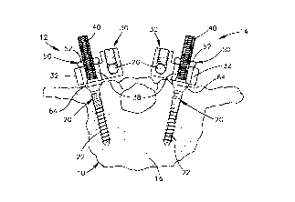
A human spinal column 10 to which a pair of retainer
assemblies 12 and 14 are connected is illustrated in Fig.
1. The retainer assemblies 12 and 14 retain portions of
the spinal column, that is vertebrae 16 in a desired
spatial relationship relative to each other.
The retainer assemblies 12 and 14 have the same
construction and include 'fasteners 20 constructed in
accordance with the present invention. In the illustrated
embodiment of the invention, the fasteners 20 are formed of
one piece of biocompatible material, specifically, anodized
titanium. However, the fasteners 20 could be formed of a
different material if desired. For example, the fasteners
could be formed of stainless steel.
The fasteners 20 have inner end or mounting sections
22 which engage bone in a vertebra 16 to fixedly mount the
fasteners in the vertebra. Although only a pair of
20 fasteners 20 have been shown in Fig. 1, it should be
understood that there are additional fasteners 20 connected
with adjacent vertebrae 16 of the spinal column 10.
Each of the retainer assemblies l2~and 14 (Fig. 1)
includes a longitudinal member, such as a cylindrical rod
26 which extends along the spinal column 10. The rods 26
are made of a biocompatible material, such as stainless
steel or titanium. Each of the rods 26 has a length which
is sufficient to enable the rod to span at least two of the
CA 02236947 1998-OS-06
-5-
vertebrae 16 in the spinal column 10. Of course, the
length of the rods 26 in any particular installation will
depend upon the condition to be corrected and the number of
vertebrae 16 to be held in a desired spatial relationship
relative to each other by the retainer assemblies 12 and
14. The rods 26 may be bent to conform to a desired
curvature of the spinal column 10 in all or any of the
three possible anatomic planes.
Connector assemblies 30 interconnect the rods 26 and
the fasteners 20. Each of the connector assemblies 30
includes a retainer member 32. Each of the retainer
members 32 is provided with an opening through which one of
the rods 26 extends. Each of the retainer members 32 has a
second opening or slot 38 through which a retaining section
40 of a fastener 20 extends.
Retaining clamps 50 hold the retainer members 32
against movement relative to the fasteners 20. The
retaining clamps 50 include internally threaded retainer
nuts 52 which engage threads on the retaining sections 40
of the fasteners 20. Locknuts may be provided to clamp the
retainer nuts 52 in place on the fasteners 20.
The distance between the rods 26 and the fasteners 20
can be varied while the rods 26 and fasteners are connected
with the retainer members 32 and while the fasteners 20
remain stationary relative to the vertebrae 16. To enable
temporary relative movement to occur between the rods 26
and fasteners 20, the slots 38 in the connector members 32
CA 02236947 1998-OS-06
-6-
have an oblong configuration. Therefore, a vertebra 16
engaged by a fastener 20 can be moved either toward or away
from a rod 26 which is being held substantially stationary.
The general construction of the retainer assemblies 12
is similar to the construction of retainer assemblies
disclosed in U.S. Patent No. 5,129,900. However, it should
be understood that the retainer assemblies 12 and 14 could
have any desired construction. For example, the retainer
assemblies 12 and 14 could be constructed in the manner
disclosed in U.S. Patent No. 4,854,311 or U.S. Patent No.
5,024,213 if desired.
The fastener 20, which is constructed in accordance
with the present invention, has a mounting section 22 with
a helical external thread convolution 60 (Figs. 2 and 3)
which engages one of the vertebrae 16 (Fig. 1). The thread
convolution 60 engages the bone in vertebra 16. The
retaining section 40 (Figs. 2 and 3) has a helical external
thread convolution 62 which engages one of the retainer
nuts 52.
A circular intermediate or head section 64 is disposed
between the mounting section 22 and retaining section 40.
The intermediate section 64 projects radially outward of
the mounting section 22 and retaining section 40. The
external thread convolutions 60 and 62, mounting section
22, retaining section 40, and intermediate section 64 all
have central axes which are coincident with a central axis
of the fastener 20.
CA 02236947 1998-OS-06
_7_
Fastener - Mounting and
Intermediate Sections
The mounting section 22 of the fastener 20 has the
external thread convolution 60 to connect the fastener with
a vertebra 16. The external thread convolution 60 is a
coarse helical thread convolution. A six (6) degree taper
or runout is provided at an upper (as viewed in Fig. 3) end
portion 68 of the external thread convolution 60. The
external thread convolution 60 may have a configuration
similar to the configuration disclosed in U.S. Patent No.
4,854,311. However, it should be understood that the
external thread convolution 60 could have any desired
configuration. It is believed that a relatively coarse
thread convolution will probably be preferred in order to
provide secure engagement with bone in a vertebra 16.
The intermediate section 64 (Fig. 3) is disposed in a
coaxial relationship with the mounting section 22 and
retaining section 40. The intermediate section 64 has a
generally circular cross sectional configuration. The
intermediate section 64 includes a lower side surface 72
which forms a portion of a cone.
The conical side surface 72 has a central axis which
is coincident with the central axis of the fastener 20.
The side surface 72 flares radially outward and axially
upward (as viewed in Fig. 3) from the outer end portion 68
of the mounting section 22 toward the retaining section 40.
It is contemplated that the side surface 72 may be pressed
CA 02236947 1998-OS-06
_8_
against a vertebra 16 when the fastener 20 is used to
retain the vertebrae in a desired spatial relationship.
The intermediate section 64 also includes a
cylindrical side surface 74 which is disposed in a coaxial
relationship with the conical side surface 72 and the
mounting section 22. A pair of identical recesses 78 and
80 (Fig. 2) are formed in diametrically opposite portions
of the intermediate section 64. The recesses 78 and 80
have generally rectangular (Fig. 4) open end portions which
face upwardly (as viewed in Fig. 2) toward the retaining
section 40. The recess 78 (Fig. 3) has an arcuate bottom
surface 82 with a center of curvature disposed on a radius
of the cylindrical side surface 74. The recesses 78 and 80
are engageable by a suitable tool to rotate the mounting
section 22 relative to a vertebra 16.
Fastener -
Retaining~ Section Flats
The retaining section 40 (Figs. 2 and 3) of the
fastener 20 is formed as one piece with and is disposed in
a coaxial relationship with the mounting section 22 and
intermediate section 64. The external thread convolution
62 on the retaining section 40 is disposed in a coaxial
relationship with the external thread convolution 60.on the
mounting section 22. A retainer nut 52 (Fig. 1) engages
the external thread convolution 62 on the retaining section
40 to hold the retainer member 32 against movement relative
to the fastener 20.
CA 02236947 1998-OS-06
_g_
In accordance with a feature of the present invention,
parallel flats 88 and 90 (Fig. 4) are formed on opposite
sides of the retaining section 40. The parallel flats 88
and 90 extend between axially opposite ends of the
retaining section 40 (Fig. 2). The identical flats 88 and
90 engage parallel sides of the slot 38 (Fig. 1) in the
retainer member 32 to block relative rotation between the
fastener 20 and the retainer member 32.
The slot 38 in the retainer member 32 is sized so as
to accommodate sliding adjustment between the retainer
member 32 and fastener 20. Of course, when the retainer
nut 52 is tightened, the retainer member 32 is securely
clamped between the intermediate section 64 and the
retainer nut to hold the retainer member against movement
relative to the fastener 20.
The flats 88 and 90 (Fig. 4) are separated by a
distance which is substantially equal to or greater than a
root diameter of the external thread convolution 62. The
external thread convolution 62 has helical flank surfaces
94 and 96 (Fig. 6) which intersect at a helical crest 98
and a helical root 100 of the external thread convolution
62. The external thread convolution 62 is formed in a
cylindrical shank portion 104 of the retaining section 40.
In the illustrated embodiment of the retaining section
40, the distance between the flats 88 and 90 (Fig. 4) is
equal to the root diameter of the external thread
convolution 62. This results in the parallel flats 88 and
CA 02236947 1998-OS-06
-10-
90 extending tangentially to the root 100 of the external
thread convolution 62. Therefore, the minimum distance
between the flats 88 and 90, that is, the distance as
measured along a diametral axis perpendicular to the flats,
is equal to the diameter of the root 100 of the external
thread convolution 62.
By having the distance between the flats 88 and 90
(Fig. 4) equal to the root diameter of the external thread
convolution 62, the shank portion 104 of the retaining
section 90 is not weakened by removal of material to form
the flats 88 and 90. In order to form the flats 88 and 90,
only the material of the external thread convolution 62 is
removed from the retaining section 40. This results in the
strength of the shank portion 104 being substantially the
same before and after the flats 88 and 90 are formed on the
retaining section 40.
When the fastener 20 is being formed, the external
thread convolution 62 is formed into the shank portion 104
of the retaining section 40. Thereafter, the flats 88 and
90 are formed. During formation of one embodiment of the
fastener 20, the flats 88 and 90 were formed by machining
the retaining section 40 to remove material from the
external thread convolution 62. To form the flats 88 and
90, metal in the external thread convolution 62 was removed
by a milling operation. However, the flats 88 and 90 could
be formed by grinding if desired.
CA 02236947 1998-OS-06
-11-
The parallel flats 88 and 90 extend from the
intermediate section 64 to the upper (as viewed in Fig. 3)
end of the retaining section 40. The parallel flats 88 and
90 have the same configuration. The configuration of the
flat 90 is illustrated in Fig. 5. The flat 90 includes a
plurality of generally diamond-shaped sections 110. The
sections 110 all have the same configuration.
Each of the sections 110 of the flat 90 is formed by
cutting away the material on one turn of the helical
external thread convolution 62. The crest 98 of a turn of
the external thread convolution 62 is interrupted at an
edge of the flat 90. Therefore, each of the sections 110
of the flat 90 has pointed ends 114 and 116 (Fig. 5) where
a flat surface 118 of the section 110 intersects the crest
98 of one of the turns of the helical external thread
convolution 62.
Each of the sections 110 of the flat 90 has a
relatively wide central portion 120. The flat surface 118
of the flat 90 is tangential to the root 100 (Fig. 5) of
the external thread convolution 62 at the wide central
portion 120 of each of the sections 110. At a line of
tangency of the plane in which the flat 90 is disposed with
the root diameter 100 of the thread convolution 62, there
is a linear area where the sections 110 of the flat 90
intersect.
The crest 98 of each turn in the external thread
convolution 62 is interrupted for the entire width of the
CA 02236947 1998-OS-06
-12-
flat 90, that is, for the distance between the pointed ends
114 and 116 of the section 110. However, the root 100 of
the external thread convolution 62 is interrupted only at
the line of tangency of the plane in which the flat 90 is
disposed with the root 100 of the external thread
convolution.
Each of the sections 110 of the flat 90 is formed by a
flat surface. The flat surfaces 118 of the sections 110
extend between their pointed ends 114 and 116 and are
disposed in a plane which extends parallel to a
longitudinal central axis of the fastener 20 and parallel
to a plane containing the flat 88 (Fig. 4). The pointed
ends 114 and 116 are disposed at opposite edge portions of
the flat 90. The opposite edge portions of the flat 90
extend parallel to the central axis of the retaining
section 40.
If the spacing between the flats 88 and 90 is somewhat
less than the diameter of the root 100 of the external
thread convolution 62, the circumferential extent or width
of the sections 110 of the flat 90 (Fig. 5) is increased.
When this happens, the width of the area where the central
portions 120 of the sections 110 intersect is increased.
However, if the distance between the flats 88 and 90 is
less than the diameter of the root 100 of the external
thread convolution 62, material is removed from the shank
portion 104 of the retaining section 40.
CA 02236947 1998-OS-06
-13-
In order to maximize the strength of the retaining
section 40, it is believed that it will probably be desired
to have the minimum distance between the flats 88 and 90 at
least as great as the diameter of the root 100 of the
external thread convolution 62. However, there may be
circumstances when the increased flat width obtained by
having the distance between the flats 88 and 90 less than
the diameter of the root 100 of the external thread
convolution 62 justifies decreasing the strength of the
shank portion 104 of the retaining section 40.
Fastener -
RetaininQ Section Drive
A drive recess 130 (Figs. 2, 3 and 6) is formed in the
outer or upper end portion of the retaining section 40.
The drive recess 130 receives a drive tool (not shown).
Force is applied to the drive tool to rotate the fastener
relative to the vertebra 16.
The drive recess 130 includes a cylindrical main
portion 134 and a plurality of arcuate corner portions 138
20 (Figs. 4 and 6). The arcuate corner portions 138 receive
projecting portions of the drive tool. Force is
transmitted from the drive tool to the arcuate corner
portions 138 of the recess 130 to rotate the fastener 20
relative to a vertebra 16.
In accordance with a feature of the present invention,
the arcuate corner portions 138 are offset from a plane
which contains the center line of the fastener 20 and
CA 02236947 1998-OS-06
-14-
extends perpendicular to the flats 88 and 90. The plane
which contains the center line of the fastener 20 and
extends perpendicular to the flats 88 and 90 is a diametral
plane of the fastener and has been indicated at 144 in Fig.
4.
By having the arcuate corner portions 138 offset from
the diametral plane 144, the corner portions are disposed
in a portion of the shank where the external thread
convolution 62 has not been interrupted to form the flats
88 and 90. This tends to maximize the strength of the
shank portion 104 at the locations where the arcuate corner
portions 138 are formed. The strength of the shank portion
104 is also promoted by the stress minimizing arcuate
configuration of the corner portions 138. Therefore, the
corner portions 138 are capable of transmitting relatively
large driving forces (torque) without fracturing of the
material of the shank portion 104 adjacent to the corner
portions 138.
A generally cylindrical main portion 134 (Fig. 6) of
the drive recess 130 includes a cylindrical side wall 148
and a conical bottom wall 150. The cylindrical side wall
148 is connected with a flat annular end surface 154 on the
shank portion 104 by a sloping countersink surface 156
which is formed as a portion of a cone. The cylindrical
side wall 148, bottom wall 150 and countersink surface 156
of the drive recess 130 are disposed in a coaxial
CA 02236947 1998-OS-06
-15-
relationship with a longitudinal central axis of the
retaining section 40 and fastener 20.
The arcuate corner portions 138 (Fig. 4) of the drive
recess 130 extend radially outward from the cylindrical
side wall 148. The arcuate corner portions 138 are
disposed in a circular array about an axis which is
coincident with the longitudinal central axis of the
retaining section 40 and fastener 20. The arcuate corner
portions 138 are spaced equal arcuate distances apart about
the central axis of the fastener 20.
In the illustrated embodiment of the invention, there
are six arcuate corner portions 138 (Fig. 4) which are
spaced 60 degrees apart. It should be noted that the two
corner portions 138 which are closest to the flat 88 are
both offset by 30 degrees from the diametral plane 144
through the center of the flat 88. Similarly, the corner
portions 138 which are closest to the flat 90 are both
offset by 30 degrees from the portion of the plane 144
which extends through the center of the flat 90. Of
course, if a different number of corner portions 138 were
provided in the drive recess 130, the arcuate distance
between the corner portions would be different and the
arcuate distance by which the corner portions are offset
from the plane 144 would be different.
The corner portions 138 all have the same
configuration. Each of the corner portions 138 includes an
arcuate, radially outwardly projecting, side surface 162
CA 02236947 1998-OS-06
-16-
(Fig. 6). Each of the arcuate side surfaces 162 has a
longitudinal central axis which extends parallel to the
coincident central axes of the drive recess 130 and the
retaining section 40. The arcuate side surfaces 162 have a
continuously curving configuration and are free of stress
inducing discontinuities which would result from sharply
defined corner portions.
As is perhaps best seen in Fig. 6, each of the corner
portions 138 has a pair of flat side surfaces 164 and 166
which flare outwardly from the arcuate side surface 162.
The flat side surfaces 164 and 166 extend between an
arcuate side surface 162 and the cylindrical side wall 148
of the main portion 134 of the drive recess 130. Each of
the corner portions 138 has a flat inner end surface 170
(Fig. 6) which extends radially outward from the
cylindrical side wall 148 of the drive recess 130.
Diametrically opposite corner portions 138 are spaced apart
by a distance which is less than the distance between the
flats 88 and 90.
A drive tool (not shown) has an end portion which fits
into the drive recess 130. The drive tool has a plurality
of radially outwardly extending projections which are
configured for mating engagement with the corner portions
138. When the drive tool is inserted into the recess 130,
the drive tool mates with all six of the corner portions
138. Upon application of torque to the drive tool, force
CA 02236947 1998-OS-06
-17-
is transmitted to all six of the corner portions 138. This
force rotates the fastener 20 relative to the vertebra 16.
Although one specific configuration for the drive
recess 130 has been illustrated in Figs. 4 and 6, it is
contemplated that the drive recess could have a different
configuration if desired. For example, the drive recess
130 could have radially inwardly curving side walls
disposed between the corner potions 138. The radially
inwardly curving side walls between the corner portions 138
would form lobes which would increase the extent of
engagement of the fastener 20 with the drive tool.
Fastener - Second Embodiment
In the embodiment of the fastener 20 illustrated in
Figs. 1-6, the flats 88 and 90 extend tangentially to the
root 100 of the external thread convolution 62. Thus, in
the embodiment of the fastener 20 illustrated in Figs. 1-6,
the distance between the flats 88 and 90 is equal to the
root diameter of the external thread convolution 62. In
the embodiment of the invention illustrated in Fig. 7, the
distance between the flats on the retaining section of the
fastener is greater than the root diameter of the thread
convolution. Since the embodiment of the invention
illustrated in Fig. 7 is generally similar to the
embodiment of the invention illustrated in Figs. 1-6,
similar numerals will be utilized to designate similar
components, the suffix letter °a" being associated with the
numerals of Fig. 7 in order to avoid confusion.
CA 02236947 1998-OS-06
-18-
A fastener 20a has the same general construction as
the fastener 20 of Figs. 2 and 3. The fastener 20a
includes a retaining section 40a having a helical external
thread convolution 62a. The fastener 20a also has a
mounting section and intermediate section (not shown)
corresponding to the mounting and intermediate sections 22
and 64 on the fastener 20 (Fig. 2).
In accordance with a feature of this embodiment of the
invention, a flat 90a (Fig. 7) on the retaining section 40a
is spaced from the central axis of the fastener 20a by a
radial distance which is greater than the radius of a root
100a of the external thread convolution 62a. Thus, the
distance between the parallel flats on the retaining
section 40a is greater than the root diameter of the
external thread convolution 62a. This results in the
external thread convolution 62a having an uninterrupted
helical root 100a. Although the flat 90a does not
interrupt the root 100a of the external thread 62a, the
flat 90a interrupts the crest 98a of the external thread
62a.
Since the flats on the retaining section 40a are
spaced apart by a distance which is greater than the root
diameter of the helical external thread~convolution 62a, a
portion of the thread convolution extends across each of
the flats. Thus, the sections 110a of the flat 90a are
separated by grooves. These grooves include the root 100a
of the external thread convolution 62a. The root 100a of
CA 02236947 1998-OS-06
-19-
the external thread convolution extends across the flat
90a.
The flat 90a was formed by cutting away material from
the flanks 94a and 96a of the external thread convolution
62a. This results in the formation of a plurality of
spaced apart sections 110a. The sections 110a extend
between pointed ends 114a and 116a. The distance between
the pointed ends 114a and 116a is less than the distance
between the pointed ends 114 and 116 of the sections 110 of
the flat 90 of Fig. 5. Therefore, the sections 110a of the
flat 90a of Fig. 7 have a smaller width than the sections
110 of the flat 90 (Fig. 5).
Although only the flat 90a is illustrated in Fig. 7,
it should be understood that the fastener 20a has a second
flat, corresponding to the flat 88 of Fig. 4, which extends
parallel to the flat 90a. The second flat, which extends
parallel to the flat 90a, has the same configuration as the
flat 90a. The root 100a of the thread convolution 62a
extends across the second flat which extends parallel to
the flat 90a.
Conclusion
The present invention provides a new and improved
fastener 20 to retain vertebrae 16 in a.desired spatial
relationship. The fastener 20 includes a mounting section
22 having an external thread 60 which engages a vertebra.
The fastener has a retaining section 40. The retaining
section 40 may have a pair of parallel flats 88 and 90
CA 02236947 1998-OS-06
-20-
disposed on opposite sides of the retaining section. In
addition, the retaining section 40 may have a drive recess
130 disposed between the flats 88 and 90 at end of the
retaining section. The drive recess 130 has a plurality of
arcuate corner portions 138 which are offset from a plane
144 containing a longitudinal central axis of the retaining
section 40 and extending perpendicular to the flats 88 and
90.
An external thread 62 may be provided around the
retaining section 40 to engage an internal thread on a
retaining element 52. The flats 88 and 90 on the retaining
section 40 may be spaced apart by a distance which is at
least as great as a root diameter 100 of the external
thread 62 on the retaining section.