Sélection de la langue

Search

Sommaire du brevet 2238022 

Énoncé de désistement de responsabilité concernant l'information provenant de tiers

Une partie des informations de ce site Web a été fournie par des sources externes. Le gouvernement du Canada n'assume aucune responsabilité concernant la précision, l'actualité ou la fiabilité des informations fournies par les sources externes. Les utilisateurs qui désirent employer cette information devraient consulter directement la source des informations. Le contenu fourni par les sources externes n'est pas assujetti aux exigences sur les langues officielles, la protection des renseignements personnels et l'accessibilité.

Disponibilité de l'Abrégé et des Revendications

L'apparition de différences dans le texte et l'image des Revendications et de l'Abrégé dépend du moment auquel le document est publié. Les textes des Revendications et de l'Abrégé sont affichés :

  • lorsque la demande peut être examinée par le public;
  • lorsque le brevet est émis (délivrance).
(12) Demande de brevet: (11) CA 2238022
(54) Titre français: PROCEDE DE FABRICATION D'UN TUBE D'ASPIRATION POUR L'EVACUATION DE LA SALIVE, ET TUBE D'ASPIRATION POUR L'EVACUATION DE LA SALIVE
(54) Titre anglais: A METHOD FOR THE PRODUCTION OF A SUCTION HOSE FOR SALIVA EJECTION AND A SUCTION HOSE FOR SALIVA EJECTION
Statut: Réputée abandonnée et au-delà du délai pour le rétablissement - en attente de la réponse à l’avis de communication rejetée
Données bibliographiques
Abrégés

Abrégé français

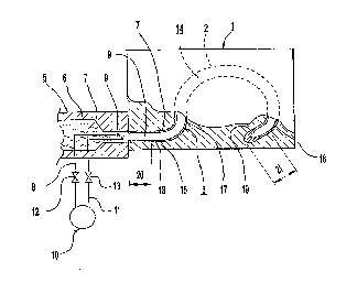
L'invention concerne un procédé de production ou de fabrication d'un tube d'aspiration (3), ainsi qu'un tube d'aspiration (3) destiné à l'évacuation de la salive. Le tube d'aspiration (3) est préformé en un élément tubulaire arqué (14) comportant deux branches (15, 16) et ayant des propriétés élastiques intrinsèques qui lui permettent de générer des forces de rappel ou de remise en place (K).


Abrégé anglais


The present invention relates to a method for the production or manufacture of
a suction hose (3) as well as a suction hose (3) for saliva ejection, which
suction hose (3) is preformed to an arcuate hose member (14) with two shanks
(15, 16) and built-in elastic properties for generating return or resetting
forces (K).

Revendications

Note : Les revendications sont présentées dans la langue officielle dans laquelle elles ont été soumises.


7.
Claims:
1. Method for the production of a suction hose for
saliva ejection, which suction hose (3) is adapted to be
located in a suction position (S) in the mouth (22) of
a patient (23) and to be retained in this position by
bringing it to engage the chin (25) of the patient (23),
characterized in that the suction hose
(3) is manufactured through a gas-assisted injection
molding method known per se, whereby said suction hose (3)
is formed with an arcuate hose member (14) with two
shanks (15, 16) and that the arcuate hose member (14)
during said manufacture is given such elastic properties
that it springs back when it is expanded by increasing
the distance (A) between said shanks (15, 16).
2. Method according to claim 1, characterized
in that the arcuate hose member (14) during said
manufacture is given such elastic properties that the
magnitude of its return or resetting force (K) is limited in
order not to subject the patient (23) to unpleasant pressure
in the mouth (22) and/or on the chin (25).
3. Method according to claim 1 or 2, characterized
in that the arcuate hose member (14)
during said manufacture is formed so that it is bent in
more than 180° and preferably in 220-260°.
4. Method according to any preceding claim,
characterized in that the suction hose (3)
during said manufacture is formed with a distance (A) of
15-35 mm between said shanks (15, 16).
5. Method according to any preceding claim,
characterized in that the suction hose (3)
during said manufacture is provided with at least one hook
portion (30) for attaching a suction body (24) to said
suction hose (3).
6. Method according to any preceding claim,
characterized in that the suction hose (3)
during said manufacture is provided with a conically

8.
tape-ring end portion (26) for connection of said suction
hose (3) to suction means (28) with unequally sized coupling
portions (27), namely suction means (28) which are
adapted for sucking out saliva from the suction hose (3).
7. Method according to any preceding claim,
characterized in that the suction hose (3) during
said manufacture is provided with two outer reject
or disposable portions (20, 21) in connection with its
shanks (15, 16), namely reject portions (20, 21) wherein
irregularities in the material and/or defects conditioned
by the manufacture appear and that said reject portions
(20, 21) are removed after the manufacture.
8. Method according to any preceding claim,
characterized in that the suction hose (3)
during said manufacture is formed of polymer material (7)
without bendable forming wire or wires which is/are
adapted to maintain the suction hose (3) in bent shape.
9. Method according to any preceding claim,
characterized in that the suction hose (3)
during said manufacture is formed of polymer material (7)
in the form of polyethylene material.
10. Method according to any preceding claim,
characterized in that the suction hose (3) is
manufactured with a suction body (24) attached thereto.
11. Method according to claim 10, characterized
in that the suction hose (3) is manufactured
with the suction body (24) attached thereto through
at least one retaining means (38) which permits relocation
or displacement of the suction body (24) from
un-assembled positions (A; fig. 6) for assembly in a suction
position (B; fig. 6) on a connecting member (39) of the
suction hose (3).
12. Method according to claim 10 or 11, characterized
in that the suction hose (3) is manufactured
with the suction body (24) attached to the outer
end of a retaining means (38) the inner end of which is
attached to the suction hose (3) adjacent a connecting

9.
member (39) of said suction hose (3) through which the
suction body (24) can be mounted in a suction position
(B; fig. 6).
13. Method for the production of a suction hose for
saliva ejection and a suction body to be mounted on said
suction hose, characterized in that the
suction hose (3) and the suction body (24) are manufactured
attached to each other.
14. Method according to claim 13, characterized
in that the suction hose (3) is manufactured
with the suction body (24) unassembled therewith but
attached thereto through at least one retaining means
(38) which permits mounting of the suction body (24) in
a suction position (B; fig. 6) on a connecting member
(39) of the suction hose (3).
15. Method according to claim 13 or 14, characterized
in that the suction hose (3) is manufactured
with the suction body (24) attached to the outer
end of a retaining means (38) the inner end of which is
attached to the suction hose (3) adjacent a connecting
member (39) of said suction hose (3) through which the
suction body (24) can be mounted.
16. Suction hose for saliva ejection and adapted to
be located in a suction position (S) in the mouth (22)
of a patient (23) and to be retained in this position by
bringing it to engage the chin (25) of the patient (23),
characterized in that the suction hose
(3) is manufactured through a gas-assisted injection
molding method known per se and comprises an arcuate hose
member (14) with two shanks (15, 16) and that the arcuate
hose member (14) during said manufacture has been given
such elastic properties that it springs back when it is
expanded by increasing the distance (A) between said
shanks (15, 16).
17. Suction hose according to claim 16, characterized
in that the arcuate hose member (14)
has such elastic properties that the magnitude of its

10.
return or resetting force (K) is limited so that the suction
hose (3) does not subject the patient (23) to unpleasant
pressure in the mouth (22) and/or against the chin
(25).
18. Suction hose according to claim 16 or 17,
characterized in that the arcuate hose member
(14) is bent in more than 180°, preferably in 220-260°.
19. Suction hose according to any of claims 16-18,
characterized in that said suction hose
(3) during said manufacture is provided with a distance
(A) of 15-35 mm between the shanks (15, 16).
20. Suction hose according to any of claims 16-19,
characterized in that the arcuate hose
member (14) is bent in more than 180°, preferably in
220-260°, and that the distance (A) between the shanks
(15, 16) is 15-35 mm.
21. Suction hose according to any of claims 16-20,
characterized in that said suction hose
(3) comprises at least one hook portion (30) for attaching
a suction body (24) to said suction hose (3).
22. Suction hose according to claim 21, characterized
in that its hook portion (30) can be
snapped into a recess (31) in the suction body (24) and
that said hook portion (30) is received in said recess
(31) with such clearance that said suction hose (3) is
somewhat pivotally engaged in said suction body (24).
23. Suction hose according to any of claims 16-22,
characterized in that said suction hose
(3) has a conically tapering end portion (26) for connection
thereof to suction means (28) with unequally large
coupling portions (27), namely suction means (28) which are
adapted for sucking out saliva from the suction hose (3).
24. Suction hose according to any of claims 16-23,
characterized in that said suction hose
(3) consists of polymer material (7) without bendable
forming wire or forming wires which is/are adapted to
maintain the suction hose (3) in bent shape.

11
25. Suction hose according to any of claims 16-24,
characterized in that said suction hose
(3) consists of polymer material (7) in the shape of
polyethylene material.
26. Suction hose according to any of claims 16-25,
characterized in that the suction hose
(3) has a suction body (24) attached thereto.
27. Suction hose according to claim 26,
characterized in that the suction body (24) is connected
with the suction hose (3) through at least one retaining
means (38) which permits relocation or displacement
of the suction body (24) from unassembled positions
(A; fig. 6) for assembly in a suction position (B; fig. 6)
on a connecting member (39) of the suction hose (3).
28. Suction hose according to claim 27,
characterized in that the suction body (24) is attached
to the outer end of a retaining means (38) the
inner end of which is attached to the suction hose (3)
adjacent a connecting member (39) of said suction hose
(3) through which the suction body (24) can be mounted
in a suction position (B; fig. 6).
29. Suction hose for saliva ejection and a suction
body to be mounted on said suction hose,
characterized in that the suction hose (3) and the
suction body (24) are attached to each other.
30. Suction hose according to claim 29,
characterized in that the suction body (24) is
connected with the suction hose (3) through at least one
retaining means (38) which from unassembled positions (A;
fig. 6) permits mounting of the suction body (24) in a
suction position (B; fig. 6) on a connecting member (39)
of the suction hose (3).
31. Suction hose according to claim 29 or 30,
characterized in that the suction body (24) is
attached to the outer end of a retaining means (38) the
inner end of which is attached to the suction hose (3)
adjacent a connecting member (39) of said suction hose

12
(3) through which the suction body (24) can be mounted
in a suction position (B; fig. 6).
32. Suction hose according to any of claims 16-31,
characterized in that the suction body
(24) includes an upwardly directed flange (32) which is
thinner than members or parts of the suction body (24)
located beneath said flange (32).
33. Suction hose according to any of claims 16-32,
characterized in that said suction hose
(3) is used for other purposes within the area of
medical technigue than for saliva ejection.

Description

Note : Les descriptions sont présentées dans la langue officielle dans laquelle elles ont été soumises.


CA 02238022 1998-0~-19
W O 97/18773 PCTISE96/01505
1.
A method for the production of a suction hose for saliva
ejection and a suction hose for saliva ejection.
The present invention relates to a method for the
production of a suction hose for saliva ejection, which
suction hose is adapted to be located in an ejecting or
suction position in the mouth of a patient and to be re-
5 t~; n~ in this position by bringing it to engage the chinof the patient. The invention also relates to a suction
hose for saliva ejection.
Suction hoses ~or saliva ejection are often manu~ac-
tured as a straight hose of polyvinyl chloride material
(PVC-material) with one or more metallic forming wires.
These wires can be bent for bending the straight hose to
any suitable shape for adapting said hose to the patient.
The forming wire/wires enables/enable the suction hose
to maintain its bent shape.
Since said suction hoses consist of PVC- as well as
metallic material, they are difficult to destruct in a
non-polluting manner, particularly since the PVC-material
is regarded as a biological danger.
The object of the present invention is to eliminate
this problem and provide a method for the production of
suction hoses which are entirely recoverable. This is
arrived at according to the invention by providing the
initially defined method with the characterizing features
of subsequent claim 1.
The invention also relates to a suction hose having
substantially the characterizing features of subsequent
claim 16 or 29.
Since the suction hose o~ claim 16 is manufactured
with a pre-bent shape, no forming wires are re~uired and
thus, the suction hose can be made of a single material
which is entirely recoverable. Furthermore, the suction
hose is from the beg; nn; ng given an advantageous shape
and elasticity.

CA 02238022 1998-0~-19
W O 97/18773 PCT/SE96/01505
2.
Since the suction hose of claim 29 and a suction
body mounted on said suction hose cling to each other,
it is ensured that said suction body, after mounting on
the suction hose, can not loosen completely there~rom and
glide down into the throat of the patient.
The invention will be further described below with
reference to the accompanying drawings, wherein
fig. 1 with a side view and partly in section illust-
rates a mold device for carrying through the method of
the invention and produce a suction hose for saliva ejec-
tion;
fig. 2 with a side view illustrates a suction hose
produced in the mold device of fig. 1;
fig. 3 with a side view illustrates a suction hose
according to fig. 2 during use on a patient;
fig. 4 with a side view illustrates a suction hose
with a suction body of different shape than the one illust-
rated in ~ig. 3;
fig. 5 is a section V-V through the suction body of
fig. 4;
fig. 6 with a side view illustrates a suction hose
with an associated suction body of another appearance
than the suction bodies in the preceding figs.; and
fig. 7 illustrates the suction hose and suction body
of fig. 6 with the suction body mounted on the suction
hose.
In fig. 1 there is illustrated a molding tool 1 with
a c~avity 2 for the production of a suction hose 3 for a
saliva eiector 4. A nozzle 5 can be connected to the mol-
ding tool 1 so that said nozzle commlln;cates with thecavity 2. The nozzle 5 has a passage 6 for liquid poly-
mer material 7, preferably polyethylene material, which
is pressurized towards the cavity 2. The nozzle 5 further
comprises a gas conduit 8 for the supply of nitrogen gas
9 or another suitable gas at high pressure from a contai-
ner lQ.
-

CA 02238022 1998-0~-l9
W O 97/18773 PCT/SE96/01505
The method for manufacturing the suction or ejector
hose 3 is initiated by simultaneously feeding or injec-
ting the polymer material 7 and the nitrogen gas 9 into
the cavity 2 so that the nitrogen gas 9 pushes the poly-
mer material 7 against the cavity walls, so that saidmaterial forms a thin-walled suction hose 3. This gas-
-assist injection molding is already known and is there-
fore not described in detail here; it should be mentioned
however, that there is a return conduit 11 for nitrogen
gas from the cavity 2 to the gas cont~;ner 10 and schemati-
cally illustrated stop valves 12, 13 are mounted in said
conduits 8, 11.
The cavity 2 is designed to produce a suction hose 3
having an arcuate hose member 14 and two shan~s 15, 16
protruding from opposite sides thereof. Thus, the cavity
2 is designed for producing a NpreformedN arcuate ho~e
member 14, which is bent in more than 180~, pre~erably
220-260~. Furthermore, the cavity 2 is preferably desig-
ned so that the distance A between the shanks 15, 16 is
15-35 mm and that one shank 15 includes an ~-shaped member
17 through which it is transformed into the arcuate hose
member 14 while the other shank 16 has no such S-shaped
member. The cavity 2 is also designed so that the shank
16 is substantially straight and that the shank 15 forms
a straight member in connection with said S-shaped mem-
ber 17. Also, two extended portions 18, 19 can be located
at the beg; nn; n~ and at the end of the cavity 2 for re-
ceiving such rough and defective reject portions 20 and
21 which are often formed at this type of injection mol-
ding processes and which must be removed after removal ofthe suction hose 3 from the cavity 2.
During the manufacture, the shape, wall thickness and
polymer material are selected so that the arcuate hose
member 14 gets elastic properties which permit said mem-
ber 14 to spring back when it is expanded by increasingthe distance between the shanks 15, 16 (e.g. from the dis-
tance A to the distance B between said shanks 15, 16). The

CA 02238022 1998-0~-19
W ~ 97/18773 PCT/SE96/01505
4.
return or resetting force K thus obtained, is used for
locating the saliva ejector 4 in a suction position S in
the mouth 22 of a patient 23 so that a suction or ejec-
tor body 24 is situated in the mouth or oral cavity 22
at the root of the tongue while the S-shaped member 17
of the shank 15 engages the chin 25 of the patient 23.
Said elastic properties are selected preferably so that
the magnitude of the return force K is limited in order
not to discomfort the patient 23 due to unpleasant pres-
sure in the mouth 22 and/or against the chin 25.
One shank 15 of the suction hose 3 may include a co-
nically tapering end portion 26 for enabling connection
of said suction hose 3 to unequally sized coupling por-
tions 27 on suction means 28, e.g. hoses, for sucking out
saliva from the suction hose 3.
When using a particular suction or ejector body 24
it should be mentioned that said body has a passage 29
into which the shank 16 can be inserted. The shank 16 may
include one or another suitable number of hook portions
30 and the suction body 24 may have a recess 31 for each
hook portion 30, whereby the recess 31 is larger than
the hook portion 30 so that said hook portion 30 is re-
ceived with clearance in said recess 31. Hereby, the suc-
tion body 24 will be somewhat pivotable relative to the
shank 16 when said suction body 24 is mounted thereon.
The suction body 24 illustrated in fig. 4 is at the
top provided with an upwardly directed flange 32. As is
shown in fig. 5, the flange 32 is thinner than the mem-
bers of the suction body 24 located beneath said flange
32. The flange 32 is adapted to define a barrier between
the patient's tongue and the point of treatment and since
it is t~; nner than other parts of the suction body 24,
it does not need much space in the mouth.
The suction body 24 of figs. 4 and 5 has in a manner
known per se a fore suction passage 33 which c~mmlln;cates
with a rear suction passage 34. This is in turn connected

CA 02238022 1998-0~-19
W O 97/18773 PCT~E96/01505
5.
to the suction hose 3 which in fig. 4 is illustrated with
dashed and dotted lines.
Fig. 6 illustrates a hose 3 with a suction body 24
attached thereto. This suction body consists of, in cont-
rast to the suction bodies described above, a tube piecewith lateral apertures 35, a completely or partly closed
front member 36 and an open rear member 37. This suction
body 24 is connected with the suction hose 3 through at
least one ret~;n;ng means 38 which permits relocation or
displacement of the suction body 24 from an unassembled
position A (see fig. 6) for assembly or mounting in a
suction position B (see fig. 7) on a connecting member
39 of the suction hose 3.
The ret~;n;ng means 38 can be a flexible band of
the same or similar material as the suction hose 3 and/or
the suction body 24. Furthermore, the ret~'n;ng means 38
may at an outer end be provided with the suction body 24
and at an inner end be mounted on the suction hose 3 ad-
jacent the connecting member 39, so that the suction
body 24 can be mounted on the suction hose 3 in its suc-
tion position B by threading said body 24 onto said con-
necting member 39 until the hook portion 30 of the suc-
tion hose 3 snaps into the recess 31 in the suction
body 24.
Through this latter embodiment, the suction hose 3
and the suction body 24 can be manufactured unassembled
relative to each other but attached to each other. Here-
by, the suction hose and associated suction body are held
together during packing of the members and storing and
use thereof, while it at the same time is ensured that
the suction body does not loosen completely from the suc-
tion hose so that said body can glide down into the throat
of the patient during dental treatment.
The method or object according to the invention de-
scribed above, may vary within the scope of the followingclaims. It should be mentioned that it is not necessary
to connect a suction body 24 to the suction hose 3, but

CA 02238022 l998-0~-l9
W O 97/18773 PCT/SE96/01505
6. .
the shank 16 of said hose can be designed so that it per-
mits effective suction of saliva. Additionally, it should
be mentioned that the suction hose 3 may be manufactured
of only one material without forming wires which main-
tain its bent shape. Also, the suction hose 3 may con-
sist of another thermoplastic material than polyethylene.
The suction hose 3 can be used for other purposes
within the area of medical techni~ue than for saliva ejec-
tion.

Dessin représentatif
Une figure unique qui représente un dessin illustrant l'invention.
États administratifs

2024-08-01 : Dans le cadre de la transition vers les Brevets de nouvelle génération (BNG), la base de données sur les brevets canadiens (BDBC) contient désormais un Historique d'événement plus détaillé, qui reproduit le Journal des événements de notre nouvelle solution interne.

Veuillez noter que les événements débutant par « Inactive : » se réfèrent à des événements qui ne sont plus utilisés dans notre nouvelle solution interne.

Pour une meilleure compréhension de l'état de la demande ou brevet qui figure sur cette page, la rubrique Mise en garde , et les descriptions de Brevet , Historique d'événement , Taxes périodiques et Historique des paiements devraient être consultées.

Historique d'événement

Description Date
Inactive : Morte - Aucune rép. dem. par.30(2) Règles 2006-08-08
Demande non rétablie avant l'échéance 2006-08-08
Réputée abandonnée - omission de répondre à un avis sur les taxes pour le maintien en état 2005-11-21
Inactive : Abandon. - Aucune rép dem par.30(2) Règles 2005-08-08
Inactive : Dem. de l'examinateur par.30(2) Règles 2005-02-08
Modification reçue - modification volontaire 2002-03-13
Lettre envoyée 2001-11-29
Exigences pour une requête d'examen - jugée conforme 2001-11-05
Requête d'examen reçue 2001-11-05
Toutes les exigences pour l'examen - jugée conforme 2001-11-05
Symbole de classement modifié 1998-08-14
Inactive : CIB en 1re position 1998-08-14
Inactive : CIB attribuée 1998-08-14
Inactive : Notice - Entrée phase nat. - Pas de RE 1998-07-30
Demande reçue - PCT 1998-07-29
Demande publiée (accessible au public) 1997-05-29

Historique d'abandonnement

Date d'abandonnement Raison Date de rétablissement
2005-11-21

Taxes périodiques

Le dernier paiement a été reçu le 2004-11-01

Avis : Si le paiement en totalité n'a pas été reçu au plus tard à la date indiquée, une taxe supplémentaire peut être imposée, soit une des taxes suivantes :

  • taxe de rétablissement ;
  • taxe pour paiement en souffrance ; ou
  • taxe additionnelle pour le renversement d'une péremption réputée.

Les taxes sur les brevets sont ajustées au 1er janvier de chaque année. Les montants ci-dessus sont les montants actuels s'ils sont reçus au plus tard le 31 décembre de l'année en cours.
Veuillez vous référer à la page web des taxes sur les brevets de l'OPIC pour voir tous les montants actuels des taxes.

Historique des taxes

Type de taxes Anniversaire Échéance Date payée
Taxe nationale de base - générale 1998-05-19
Enregistrement d'un document 1998-05-19
TM (demande, 2e anniv.) - générale 02 1998-11-20 1998-05-19
TM (demande, 3e anniv.) - générale 03 1999-11-22 1999-11-18
TM (demande, 4e anniv.) - générale 04 2000-11-20 2000-11-08
Requête d'examen - générale 2001-11-05
TM (demande, 5e anniv.) - générale 05 2001-11-20 2001-11-19
TM (demande, 6e anniv.) - générale 06 2002-11-20 2002-11-08
TM (demande, 7e anniv.) - générale 07 2003-11-20 2003-11-04
TM (demande, 8e anniv.) - générale 08 2004-11-22 2004-11-01
Titulaires au dossier

Les titulaires actuels et antérieures au dossier sont affichés en ordre alphabétique.

Titulaires actuels au dossier
KANOR PLAST AB
Titulaires antérieures au dossier
KAJ A. L. NORDSTROM
Les propriétaires antérieurs qui ne figurent pas dans la liste des « Propriétaires au dossier » apparaîtront dans d'autres documents au dossier.
Documents

Pour visionner les fichiers sélectionnés, entrer le code reCAPTCHA :


Pour visualiser une image, cliquer sur un lien dans la colonne description du document (Temporairement non-disponible). Pour télécharger l'image (les images), cliquer l'une ou plusieurs cases à cocher dans la première colonne et ensuite cliquer sur le bouton "Télécharger sélection en format PDF (archive Zip)" ou le bouton "Télécharger sélection (en un fichier PDF fusionné)".

Liste des documents de brevet publiés et non publiés sur la BDBC .

Si vous avez des difficultés à accéder au contenu, veuillez communiquer avec le Centre de services à la clientèle au 1-866-997-1936, ou envoyer un courriel au Centre de service à la clientèle de l'OPIC.

({010=Tous les documents, 020=Au moment du dépôt, 030=Au moment de la mise à la disponibilité du public, 040=À la délivrance, 050=Examen, 060=Correspondance reçue, 070=Divers, 080=Correspondance envoyée, 090=Paiement})


Description du
Document 
Date
(aaaa-mm-jj) 
Nombre de pages   Taille de l'image (Ko) 
Dessin représentatif 1998-08-20 1 8
Revendications 1998-05-18 6 263
Description 1998-05-18 6 271
Abrégé 1998-05-18 1 49
Dessins 1998-05-18 5 70
Avis d'entree dans la phase nationale 1998-07-29 1 209
Courtoisie - Certificat d'enregistrement (document(s) connexe(s)) 1998-07-30 1 140
Rappel - requête d'examen 2001-07-22 1 118
Accusé de réception de la requête d'examen 2001-11-28 1 179
Courtoisie - Lettre d'abandon (R30(2)) 2005-10-16 1 167
Courtoisie - Lettre d'abandon (taxe de maintien en état) 2006-01-15 1 174
PCT 1998-05-18 8 305
Taxes 2003-11-03 1 37
Taxes 1999-11-17 1 51
Taxes 2001-11-18 1 46
Taxes 2002-11-07 1 35
Taxes 2000-11-07 1 32
Taxes 2004-10-31 1 34