Sélection de la langue

Search

Sommaire du brevet 2238593 

Énoncé de désistement de responsabilité concernant l'information provenant de tiers

Une partie des informations de ce site Web a été fournie par des sources externes. Le gouvernement du Canada n'assume aucune responsabilité concernant la précision, l'actualité ou la fiabilité des informations fournies par les sources externes. Les utilisateurs qui désirent employer cette information devraient consulter directement la source des informations. Le contenu fourni par les sources externes n'est pas assujetti aux exigences sur les langues officielles, la protection des renseignements personnels et l'accessibilité.

Disponibilité de l'Abrégé et des Revendications

L'apparition de différences dans le texte et l'image des Revendications et de l'Abrégé dépend du moment auquel le document est publié. Les textes des Revendications et de l'Abrégé sont affichés :

  • lorsque la demande peut être examinée par le public;
  • lorsque le brevet est émis (délivrance).
(12) Demande de brevet: (11) CA 2238593
(54) Titre français: VALVE DE GONFLAGE
(54) Titre anglais: INFLATING VALVE
Statut: Réputée abandonnée et au-delà du délai pour le rétablissement - en attente de la réponse à l’avis de communication rejetée
Données bibliographiques
(51) Classification internationale des brevets (CIB):
  • F16K 15/20 (2006.01)
  • A63B 41/12 (2006.01)
(72) Inventeurs :
  • WU, HSIN-TSAI (Taïwan, Province de Chine)
  • WU, HSIN-PING (Taïwan, Province de Chine)
(73) Titulaires :
  • BULTON ENTERPRISES CO., LTD.
(71) Demandeurs :
  • BULTON ENTERPRISES CO., LTD. (Taïwan, Province de Chine)
(74) Agent: GOWLING WLG (CANADA) LLP
(74) Co-agent:
(45) Délivré:
(22) Date de dépôt: 1998-05-22
(41) Mise à la disponibilité du public: 1998-11-30
Requête d'examen: 1998-05-22
Licence disponible: S.O.
Cédé au domaine public: S.O.
(25) Langue des documents déposés: Anglais

Traité de coopération en matière de brevets (PCT): Non

(30) Données de priorité de la demande:
Numéro de la demande Pays / territoire Date
4549/97 (Japon) 1997-05-30

Abrégés

Abrégé français

Cette invention concerne une valve de gonflage formée d'une partie intérieure et d'une partie extérieure qui comportent un premier et un second rebords périphériques collés de part et d'autre de la paroi d'un objet à gonfler, et un bouchon et une busette tubulaire centrés adaptés pour être réunis de façon étanche. Une première cloison de forme tronconique formée entre le bouchon et le premier rebord périphérique comporte une série de trous de communication avec la busette tubulaire. Une deuxième cloison de forme tronconique formée entre la busette tubulaire et le second rebord périphérique de manière à pouvoir prendre appui contre le premier rebord peut être pliée à son extrémité de grand diamètre pour séparer la busette tubulaire du bouchon.


Abrégé anglais


An inflating valve includes inner and outer pieces
which have first and second peripheral flanges for
cementing together and a central plug and a central
tubular spout to be sealingly fitted together. A
frusto-conical shaped first web portion is formed
between the plug and the first peripheral flange to
project inward from the first peripheral flange and is
provided with a plurality of passage holes for
communication with the tubular spout. A second web
portion of frusto-conical shape is formed between the
tubular spout and the second peripheral flange to abut
against the first peripheral flange and can be flexed
at its wider end so as to separate the tubular spout
from the plug.

Revendications

Note : Les revendications sont présentées dans la langue officielle dans laquelle elles ont été soumises.


WHAT I CLAIM IS:
1. An inflating valve for an inflatable, comprising:
an inner piece having a plug, a first web portion
which is formed around said plug and which has passage
holes, and a first peripheral flange which is formed
around said first web portion for attachment to the
inflatable; and
an outer piece having a tubular spout pluggable by
said plug, a second web portion formed around said
tubular spout to abut against said first web portion,
and a second peripheral flange formed around said
second web portion for cementation with said first
peripheral flange, said second web portion being
flexible to move away from said first web portion so as
to separate said tubular spout from said plug and so as
to place said tubular spout in fluid communication with
said passage holes.
2. An inflating valve as claimed in Claim 1, wherein
said first web portion is substantially frusto-conical
and projects inwardly from said first peripheral
flange, said first web portion having an outer wider
end connected to said first peripheral flange and an
inner narrower end connected to said plug, thereby
holding said plug inside said first web portion.

3. An inflating valve as claimed in Claim 2, wherein
said second web portion has a frusto-conical shape and
includes a wider end connected to said second
peripheral flange and a narrower end connected to said
tubular spout, said second web portion being capable of
flexing at said wider end thereof.
4. An inflating valve as claimed in Claim 3, wherein
said inner piece is made of a material which is more
rigid than that of said outer piece.
5. An inflating valve as claimed in Claim 3, wherein
said tubular spout has an outer end portion for
extending axially and outwardly of said plug, thereby
completely receiving said plug, said outer end portion
being provided with a radially projecting flange for
handling.

Description

Note : Les descriptions sont présentées dans la langue officielle dans laquelle elles ont été soumises.

CA 02238~93 1998-0~-22
., ,
IN~LATING VALVE
BACKGROUND OF THE INVENTION
1. Field of the Invention
This invention relates to an inflating valve,
particularly to one which has inner and outer pieces
for attachment to an inflatable and which includes a
tubular spout and a plug formed respectively in the
outer and inner pieces to protrude into the inside of
the inflatable.
2. Brief Description of the Prior Art
It is known in the art to provide inflatables,
such as, beach balls, air cushions, swimming rings,
etc., with inflating valves for filling the same with
air or gas and for preventing the escape of gas after
filling. Inflating valves generally comprise a flat
15 attachment flange to be attached to the wall of an
inflatable by a high frequency sealing process, a
tubular spout formed with the attachment flange and a
plug to be sealingly inserted into the tubular spout.
In a typical construction, the attachment flange is
20 formed at an inner wider end of a frusto-conical hollow
member, and the tubular spout disposed inside the
frusto-conical hollow member projects outwardly from
the outer narrower end of the frusto-conical hollow
member. The plug is formed on a flexible strap which
25 is hinged to outer end of the tubular spout, and a
split is formed in the circumferential wall of the

CA 02238~93 1998-0~-22
tubular spout inside the frusto-conical hollow member
to provide fluid communication between the interior
spaces of the tubular spout and the frusto-conical
hollow member, thereby permitting air to enter into the
inflatable through the tubular spout, the split and the
frusto-conical hollow member. However, several
problems are encountered in such a construction.
Firstly, since almost all parts of the inflating
valve protrude outward from the surface of the
inflatable to which it is attached, the plug is-
susceptible of separation from the tubular spout by
accident, and the protruding flexible strap thereof,
when folded to close the spout, can accidentally hurt
the user. Therefore, the location for mounting the
inflating valve must be selected so as not to be easily
touched by the body of the user when the inflatable
- article is in use. Further, the split formed in the
circumferential wall of the tubular spout must be
carefully dimensioned so as to prevent rapid escape of
gas in case of accidental separation of the plug from
the spout. The need to find acceptable dimension for
the split is inconvenient because, if the split is
large, the inflatable can be undesirably deflated at a
fast rate through the split, and if the split is small,
deflation would be so slow that a considerable amount
of time and energy is required to deflate the

CA 02238~93 1998-0~-22
inflatable so as to keep it ready for transportation or
storage.
on the other hand, because the plug is formed on a
breakable hinged strap, the inflating valve is
dangerous for an infant who may bite the strap during
playing with the inflatable. For safety purposes, some
European countries require commodity tests for such
inflating valves in order to investigate the bearing
strength of the strap, and manufacturers have to
conduct stringent quality control in producing such
inflating valves. Difficulties are encountered in
selecting materials for the valves because soft
materials are easily breakable although they would not
injure the user, whereas strong materials increase
chances of hurting the user.
SUMMARY OF THE INVENTION
An object of the invention is to provide an
inflating valve which can overcome the above-described
disadvantages.
Another object of the invention is to provide an
inflating valve which does not protrude from the
surface of an inflatable, thereby alleviating the risk
of accidentally opening the valve and hurting the user.
A further object of the invention is to provide an
inflating valve which dispenses with the use of a strap
which is breakable or susceptible of hurting the user.

CA 02238~93 1998-0~-22
These and other objects can be achieved through the
provision of an inflating valve which comprises:
an inner piece having a plug, a first web portion
which is formed around the plug and which has passage
holes, and a first peripheral flange which is formed
around the first web portion for attachment to an
inflatable; and
an outer piece having a tubular spout pluggable by
the plug, a second web portion formed around the
tubular spout to abut against the first web portion,
and a second peripheral flange formed around the second
web portion for cementation with the first peripheral
flange, the second web portion being flexible to move
away from the first web portion so as to separate the
tubular spout from the plug and so as to place the
tubular spout in a fluid communication relationship
with the passage holes.
Other objects, features and advantages of the
present invention will become more fully apparent from
the following detailed description of the preferred
embodiment with reference to the accompanying drawings.
BRIEF DESCRIPTION OF THE DRAWINGS:
Figure 1 is a sectional view of a preferred
embodiment of an inflating valve according to the
present invention in a closed position;
Figure 2 is an exploded view of the preferred

CA 02238~93 1998-0~-22
,
embodiment shown in Figure 1; and
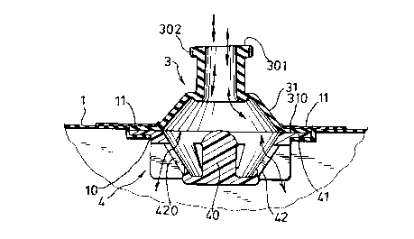
Figure 3 is a sectional view of the preferred
embodiment of Figure 1 in an opened position.
DETAILED DESCRIPTION OF THE PREFERRED EMBODIMENT
s Referring to Figures 1 and 2, a preferred
embodiment of an inflating valve according to the
present invention is shown to comprise an outer piece 3
and an inner piece 4 which are disposed in a mounting
.
hole 10 of a wall of an inflatable 1, for example, a
cushion, a swimming ring, or the like, and which are
attached to the wall of the inflatable 1 and a fixing
layer 11.
The outer piece 3 is made of a flexible plastic
material and comprises a central tubular spout 30, a
flexible web portion 31 formed around the tubular spout
31, and a peripheral flange 310 formed around the web
portion 31 for cementing to the wall of the inflatable
1. The web portion 31 has a frusto-conical shape and
includes a wider end connected to the peripheral flange
310 and a narrower end connected to the tubular spout
30. The web portion 31 is capable of flexing at the
wider end to project into or outward of the inflatable
' -1 .
The inner piece 4 is preferably made of a plastic
material more rigid than that used for the outer piece
3, and comprises a central plug 40 to be press fitted

CA 02238~93 1998-0~-22
in the tubular spout 30, a web portion 42 formed around
the central plug 40, and a peripheral flange 41 formed
around the web portion 42 for cementing to the
peripheral flange 310 and the wall of the inflatable 1.
5 The web portion 42 is generally frusto-conical and
projects inwardly from the peripheral flange 41. The
wider outer end of the web portion 42 is connected to
the peripheral flange 41, and the narrower inner end
- thereof is connected to an inner end of the central
plug 40, thereby holding the central plug 40 within the
interior space of the web portion 42. A plurality of
passage holes 420 are formed in the web portion 42 at
different angular positions, and ribs 421 project
outward from the outer surface of the web portion 42.
The web portion 31 of the outer piece 3 can be
pushed inward and placed in abutment with the web
portion 42 of the inner piece 4 to cover the passage
holes 420 when the tubular spout 30 is press fitted
into the plug 40. The tubular spout 30 has an outer
end portion 301 which extends axially and outwardly of
the outer end of the plug 40 so that the plug 40 is
entirely received in the tubular spout 30. A radially
projecting annular flange 302 is formed at the outer
end portion 301 for handling. Preferably, the annular
flange 302 is knurled to avoid slippage during
handling. By pulling the annular flange 302, the

CA 02238~93 1998-0~-22
tubular spout 30 can be removed from the plug 40.
Preferably, the tubular spout 30 may be configured such
that the passage confined thereby slightly diverges
inward so as to facilitate insertion or separation of
the plug 40.
As shown in Figure 1, after inflating the
inflatable 1, the tubular spout 30 of the outer piece 3
is pushed inward to be sleeved on the plug 40, thereby
blocking the tubular spout 30 and causing the web
portion 31 to abut against the web portion 42 and to
cover the passage holes 420. The inflating valve is in
a closed position under this situation.
Referring to Figure 3, when the inflatable is
inflated or deflated, the tubular spout 30 is pulled
outward and the web portion 31 is separated from the
web portion 42, thereby forming a space between the web
portions 31 and 42 to communicate the tubular spout 30
and the passage holes 420. The inflating valve is
thereby opened and permits air to flow into or out of
the inflatable through the tubular spout 30 and the
passage holes 420.
As shown in Figure 3, when the inflating valve is
in its closed position, except for a small portion of
the tubular spout 30 which protrudes out from the outer
surface of the inflatable 1, all other portions of the
inflating valve project inwardly from the inner surface

CA 02238~93 1998-0~-22
'
of the inflatable 1. As a result, the problems
encountered with the prior art described beforehand are
eliminated in the present invention.
With the invention thus explained, it is apparent
that various modifications and changes can be made
without departing from the scope and spirit of the
invention, especially, as defined in the following
claims.-

Dessin représentatif
Une figure unique qui représente un dessin illustrant l'invention.
États administratifs

2024-08-01 : Dans le cadre de la transition vers les Brevets de nouvelle génération (BNG), la base de données sur les brevets canadiens (BDBC) contient désormais un Historique d'événement plus détaillé, qui reproduit le Journal des événements de notre nouvelle solution interne.

Veuillez noter que les événements débutant par « Inactive : » se réfèrent à des événements qui ne sont plus utilisés dans notre nouvelle solution interne.

Pour une meilleure compréhension de l'état de la demande ou brevet qui figure sur cette page, la rubrique Mise en garde , et les descriptions de Brevet , Historique d'événement , Taxes périodiques et Historique des paiements devraient être consultées.

Historique d'événement

Description Date
Inactive : Morte - Aucune rép. dem. par.30(2) Règles 2001-08-20
Demande non rétablie avant l'échéance 2001-08-20
Réputée abandonnée - omission de répondre à un avis sur les taxes pour le maintien en état 2001-05-22
Inactive : Abandon. - Aucune rép dem par.30(2) Règles 2000-08-18
Inactive : Dem. de l'examinateur par.30(2) Règles 2000-02-18
Demande publiée (accessible au public) 1998-11-30
Symbole de classement modifié 1998-10-02
Inactive : CIB attribuée 1998-10-02
Inactive : CIB en 1re position 1998-10-02
Inactive : CIB attribuée 1998-10-02
Exigences de dépôt - jugé conforme 1998-08-05
Inactive : Certificat de dépôt - RE (Anglais) 1998-08-05
Demande reçue - nationale ordinaire 1998-08-04
Toutes les exigences pour l'examen - jugée conforme 1998-05-22
Exigences pour une requête d'examen - jugée conforme 1998-05-22

Historique d'abandonnement

Date d'abandonnement Raison Date de rétablissement
2001-05-22

Taxes périodiques

Le dernier paiement a été reçu le 2000-04-28

Avis : Si le paiement en totalité n'a pas été reçu au plus tard à la date indiquée, une taxe supplémentaire peut être imposée, soit une des taxes suivantes :

  • taxe de rétablissement ;
  • taxe pour paiement en souffrance ; ou
  • taxe additionnelle pour le renversement d'une péremption réputée.

Veuillez vous référer à la page web des taxes sur les brevets de l'OPIC pour voir tous les montants actuels des taxes.

Historique des taxes

Type de taxes Anniversaire Échéance Date payée
Requête d'examen - petite 1998-05-22
Taxe pour le dépôt - petite 1998-05-22
Enregistrement d'un document 1998-05-22
TM (demande, 2e anniv.) - petite 02 2000-05-22 2000-04-28
Titulaires au dossier

Les titulaires actuels et antérieures au dossier sont affichés en ordre alphabétique.

Titulaires actuels au dossier
BULTON ENTERPRISES CO., LTD.
Titulaires antérieures au dossier
HSIN-PING WU
HSIN-TSAI WU
Les propriétaires antérieurs qui ne figurent pas dans la liste des « Propriétaires au dossier » apparaîtront dans d'autres documents au dossier.
Documents

Pour visionner les fichiers sélectionnés, entrer le code reCAPTCHA :


Pour visualiser une image, cliquer sur un lien dans la colonne description du document. Pour télécharger l'image (les images), cliquer l'une ou plusieurs cases à cocher dans la première colonne et ensuite cliquer sur le bouton "Télécharger sélection en format PDF (archive Zip)" ou le bouton "Télécharger sélection (en un fichier PDF fusionné)".

Liste des documents de brevet publiés et non publiés sur la BDBC .

Si vous avez des difficultés à accéder au contenu, veuillez communiquer avec le Centre de services à la clientèle au 1-866-997-1936, ou envoyer un courriel au Centre de service à la clientèle de l'OPIC.


Description du
Document 
Date
(aaaa-mm-jj) 
Nombre de pages   Taille de l'image (Ko) 
Abrégé 1998-05-22 1 21
Description 1998-05-22 8 252
Revendications 1998-05-22 2 52
Dessins 1998-05-22 2 39
Page couverture 1998-12-07 1 48
Dessin représentatif 1998-12-07 1 10
Courtoisie - Certificat d'enregistrement (document(s) connexe(s)) 1998-08-05 1 140
Certificat de dépôt (anglais) 1998-08-05 1 174
Rappel de taxe de maintien due 2000-01-25 1 113
Courtoisie - Lettre d'abandon (R30(2)) 2000-10-02 1 171
Courtoisie - Lettre d'abandon (taxe de maintien en état) 2001-06-19 1 182
Taxes 2000-04-28 1 39