Note : Les descriptions sont présentées dans la langue officielle dans laquelle elles ont été soumises.
CA 02239178 1998-06-01
W O 97/19864 PCT~US96/U3048
PI~8TIC ~G CLO8 ~ E
- h~ic~ll Fi~l~ of th~ Inv~ntion
The present invention generally relates to new
and improved closures for press-on or non-rotary
application to a glass or plastic container which closures
require twisting or rotational action for removal from
such containers and, more particularly, to a closure of
this type which includes a flexible skirt having a
plurality of inwardly projecting lugs for engagement with
a multi-lead thread configuration on the neck portion of a
container to be sealed therewith.
R~ G~d of the Invention
Commercially available PT closures (i.e. those
enabling press-on or non-rotary application to a container
but requiring rotational or twisting removal) are commonly
lined with a conventional plastisol gasket compound that
is arranged to be in sealing engagement with the top edge
or finish of a container and along the neck portion
thereof. When first formed, these containers have a
cylindrical bore which is adapted to provide an
interference fit with the screw thread on the con~i n~
neck, thereby enabling the closure to be directly applied
to the container without re~uiring rotation thereof.
During thermal processing of the container after the
filling or capping thereof, this lining takes a set by
which it permanently conforms to the container's helical
thread(s) enabling subsequent rotational removal of the
closure from the container by the user.
CA 02239178 1998-06-01
W O 97/19864 PCT~US96/03048 -2-
While the~e commercial closures have ~ound
general acceptance in the trade, efforts have been
undertaken by those involved in this art to eliminate the
need for utilizing a thread-forming lining on the interior
of such closures. One such alternative closure
construction is shown in U.S. Patent 4,717,034 tMumford)
which describes a one-piece cap shell closure formed o~
thermoplafitic material for capping containers having a
plurality of vertically ~p~c~ multi-lead threads on the
neck surface thereof. The skirt portion of the closure
includes a plurality of spaced-apart, flexible and
generally vertical thermoplastic ribs which are integral
with the skirt each of which is sized to engage a
plurality of threads. These ribs are so constructed and
arranged that they impart sufficient resistance to cold
flow so that the rib only slightly flexes and bends around
the threads to form slight indentations on the ribs when
~uch ribs are forced into contact with the threads. These
axial-ribbed closures have not, insofar as applicants are
aware, found commercial acceptance. The failure of such
closures to find such acceptance by the trade i5 believed
to be due to the inability of the vertical ribs to provide
sufficient lifting, particularly under vacuum conditions,
with conventionally employed thread designs used in
currently available glass containers for use with press-
on/rotationally removable closures.
The present invention overcomes the problems and
~;~A~vantages of these prior art closures and provides a
new and improved closure having significant advantages
thereover.
~g~mary of t~e Invention
In accordance with the present invention, a new
and improved closure is provided for press-on application
to, and rotational removal from, a container having a
cylindrical neck that includes a plurality,of vertically
spaced helical threads formed on the outer surface
CA 02239178 1998-06-01
W O 97119864 PCT~US96/03048
-3-
thereof. The closures of this invention include a
flexible cylindrical skirt that extends downwardly from an
end panel which s~irt is provided with a plurality of
integrally formed rad~ally inwardly projecting spaced lugs
that are circumferentially disposed around the inner
cylindrical skirt surface and axially spaced thereon for
engagement with the threads when the closure is seated on
the cont~i ner in sealing relationship therewith. The
skirt and lugs are composed of a deformable plastic
material (preferably pol~ ~ylene) and are sized and
arranged to permit the closure to be applied to the
container by direct axial, press-on action without
requiring rotation thereof to effect the desired sealing
of the closure on the container. This sealing is achieved
by an interference fit being achieved between the lugs
which are in direct contact with the maximum outer extent
of threads on the contAiner. Each of the spaced lugs has
an axial height such that it will only be in contact with
a single helical thread when the closure is in sealing
relationship on the contA; ner. The threads also have a
circumferential length which in association with such
axial height enables at least some of them to be at least
partially received within the helical grooves formed by
the ~paced helical threads on the container so that, upon
rotational removal of the closure, a leading edge on a lug
received within such a groove will engage an upwardly
inclined surface on an ad~acent thread, thereby providing
an upward camming action to the closure during such
removal rotation.
lt is, therefore, an object of the present
invention to provide an improved closure which can be
applied to a contAin~r by a direct, axial press-on action.
Another object of the present invention is to
provide an im~ved press-on/rotationally removable
closure which does not require the use of a curable
elastomeric thread-forming deposit on the interior of the
skirt and which, at the same time, does not re~uire any
CA 02239178 1998-06-01
W O 97119864 PCT~US96/03048
-4-
cpecial registration between the closure and the COntA in~r
to achieve the de~ired sealing when the closure is applied
to the container.
Another object of the present invention is to
provide an improved closure of the press-on/rotationally
removable type for application to a glass or plastic
container having a neck finish area that includes a multi-
lead thread configuration which clo~ure can be repeatedly
pressea or snap fitted onto the contA i ne~ (without
requiring any cinching) but which is readily removed by a
twisting or rotational movement.
Another object of the present invention is to
provide an improved press-on/rotationally removable
closure which will permit the achievement of desired
venting or pressure release without adversely effecting
the force required for rotational removal of said closure.
These and other objects of the present invention
will ~e apparent from the following detailed description
taken in conjunction with the accompanying drawings or in
like reference numerals refer to like parts and in which:
FIG. 1 is a perspective view of a lug cap or
closure illustrating the inside skirt portion thereof and
also showing the tamper band portion thereof in its as-
formed or downwardly ex~n~ing position;
FIG. 2 is a perspective view of a lug cap or
closure of the present invention showing the upper surface
of the top panel thereof and with the tamper bank inwardly
folded in overlying relation to a complementary cont~;ne~
according to the present invention;
FIG. 3 is an elevational view of the closure
shown in FIGS. 1 and 2;
FIG. 4 is a top plan view of the closure shown
in FIGS. 1-3;
FIG. 5 is a vertical sectional view
illustrating the closure of FIGS. 1-4 as formed and prior
to the application of said clo5ure to a container;
_
CA 02239178 1998-06-01
W O 97119864 PCTAUS96/03048
-5-
FIG. 6 is a sectional view taken along the
lines 6-6 of the closure cap shown in FIG. 3;
FIG. 7 is a vertical sectional view similar to
FIG. 5 but showing the closure cap during an initial stage
of the operation in which it is being applied to a
cont~;n~ and prior to its being fully sèated on said
container;
FIG. 8 is a view similar to FIG. 7 but showing
the closure after it has been fully applied to the
container and after the creation of a vacuum condition in
the cont~;ne~;
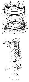
FIG. 9 is a schematic thread development
illustration showing the orientation of the lugs on the
skirt of the closure to the individual threads on the neck
portion of the container; and
FIG. 10 is a fragmentary sectional view similar
to FIG. 5 showing an alternate embodiment of the present
invention.
D~tail~ DesGription o~ the Preferred Embo~iment
~eferring to the drawings, and with particular
reference to FIGS. 1-4, a closure cap embodying the
present invention is generally designated by the reference
numeral 11. Closure cap 11 is suitable for a variety of
applications such as, for example, the hot fill packing of
food products. As shown, closure cap 11 includes an end
panel 12, a flexible skirt 13 exten~i ng downwardly
therefrom, a tamper indicating band 14 integrally formed
with the skirt 13 and a gasket 16.
In the illustrated embodiment, end panel 12 is
formed of metal, however, other materials exhibiting
suitable oxygen ~arrier or oxygen scavenging properties
can also be used such as, for example, Saran or EVOH type
materials, nylons and other thermoplastic and thermoset
resins and composite structures ~nown in the art. As best
shown in FIGS. 2, 4 and 6, end panel 12, in the
illustrated embodiment, includes an upwardly projecting
CA 02239178 1998-06-01
W O 97/19864 PCT~US96/03048 -6-
button 17 at the radial innermost portion thereof which
sequentially extends radially outwardly into a downwardly
and outwardly inclined flange 18, a flat 19, an upwardly
and outwardly inclined flange 21, an AnmllAr flat 22, a
downwardly and r~ lly outwardly inclined flange 23, a
radially ext~nAi n~ annular flat 24, a downwardly curved
section 26 and a r~ y and axially downwardly ext~
section 27 which ter~inates in a free or cut edge 28. As
is known in the art, the creation of a vacuum condition in
the contA i n~ to which the closure is applied will result
in a downwardly axial movement and depression of the panel
and button 17, while release of the vacuum will cause the
panel and button to return to their as-formed position
shown in FIG. 2.
Flexible plastic skirt 13 includes an upper
r~iAlly inwardly ext~n~ing flange 29 which overlies the
outer periphery of the end panel 12 and extend5 axially
downwardly into the sidewall 31, the inner circumferential
surface of which, in accordance with an important aspect
of the present invention, as will be described in greater
detail below, is provided with a plurslity of
circumferentially spaced lugs which are integrally formed
therewith. Flexible skirt 13 further extends into an
enlarged axially downwardly ext~n~;ng cylindrical
section 33, the terminal portion 34 of which is integrally
connected to the tamper band 14 by means of a plurality of
circumferentially disposed fracturable bridges 36 as best
shown in FIG. 3. A plurality of drain holes 35 and wash
windows 40 can be provided for facilitating the passage of
moisture during the processing of a container to which the
closure cap has been applied.
In the illustrated embodiment, flexible skirt 13
i5 in ~ r ~ ding and capturing relation to end panel 12
in a manner by which the central portion of the end
panel 12 is exposed, that is free of any overlying plastic
material. Skirt 13 is suitably composed of any plastic
resin which will afford the requisite flexibility required
CA 02239178 1998-06-01
W O 97/19864 PCT~US96/03048
-7-
to enable the closure cap 11 to be axially applied to a
cont~in~ 37 (FIG. 2) so that the inwardly projecting
lugs depicted by common reference numeral 32 will snap
over a plurality of vertically spaced helical threads
depicted by common reference numeral 38 on the cont~;n~
~ 37. As shown in FIG. 2, threads 38 are formed on the
outer surface of a neck area 39 of the con~; n~ 37 and
are in generally parallel relat~n~ ip to each other so as
to define a plurality of helical y~o~ve~ depicted by
common reference numeral 41. Neck area 39 terminates at
its upper end in a finish 42 which defines an open mouth
43 in the container. Suitable moldable resins for
skirt 13 include thermoplastic or thermoset resins,
however, homopolymers, copolymers and terpolymers of
ethylene and/or propylene are generally preferred with
propylene being especially preferred.
In the illustrated embodiment, gasket 16 is a
side seal type and is preferably formed by molding.
Gasket 16 can be composed of any resilient or elastomeric
material (i.e. thermoplastic, thermoset and plastisol
compositions) which provide the desired seal with the
~inish of a container. In this regard, however,
vinylchloride-free resins or non-PVC materials are
preferred.
As shown in FIGS. 7 and 8, tamper indicating
band 14 is joined to the skirt by the bridges 36 at a
location below a container retainer bead 45. In this
regard, it will be observed that tamper indicating band 14
includes an upper portion 46 hingedly connected at 47 to a
lower band portion 48. In the illustrated emho~iment, the
axial length of lower band portion 48 is greater than the
axial length of the upper band portion 46. In this
manner, when the closure is applied to a container, the
terminal portion 51 of the lower band 48 extends radially
inwardly and axially upwardly for engagement with the
ret~;n~r bead 45 at a location above the circumferentially
disposed bridges 36, thereby providing enhanced integrity
CA 02239178 1998-06-01
W O 97/19864 PCT/U~6,'03048
-8-
of the flangeable bridges. Inadvertent ~u~Lu~ing thereof
i8 minimized, if not totally avoided, both during
formation of the band (i.e. machine folding the~eof) and
also during application of the closure to a cont~; ne~.
Referring to FIGS. 7, 8 and 9, it will be
observed that flexible skirt 13 and the lugs integrally
formed therewith (lug 32c being specifically shown in
FIGS. 7 and 8) are sized 80 that they provide an
interference fit with the respective threads with which
they come in contact (thread~ 38b and 38c being shown in
FIGS. 7 and 8). The downward axial force imparted to the
closure 11 during the application thereof to the
container 37 causes the flexible skirt 13 to radially
outwardly ~xrAn~ enabling the lugs to outwardly ~r~n~ and
1~ ride over the threads wlth which they come in contact.
An interference fit between at least some of the lugs and
threads is thereby achieved as shown, for example, in
FIGS. 8 and 9 with respect to lug 32c and helical
thread 38c. This results in lug 32c being slightly
deformed during the application of the closure cap 11 to
the container 37. This interference fit serves to retain
the closure on the container until a vacuum is formed. As
shown in FIG. 9, similar interference fits are provided
with the lugs 32a (with thread 38b~, 32e ~with thread 38d)
and lug 32g (with thread 38e).
Correspondingly, as also shown in FIG. 9,
lugs 32b, 32d and 32f are respectively at least partially
received within the thread ~o~ves 41a, 41b and 41c. In
this manner, when the closure cap 11 is removed, the end
face or leading edge 32b' of lug 32b will engage the
upwardly inclined surface 38c' on thread 38c, thereby
providing an upward camming action to the closure cap
during such removal rotation. A similar cAmming off
action is achieved by like cooperation of end or leading
face 32d' of lug 32d with upwardly inclined surface 38d'
of thread 38d and the leading edge or end face 32f' with
upward~y inclined surface 38e' of thread 38e.
CA 02239178 1998-06-01
W O 97/19864 PCT~US961~3048
_g_
It will be appreciated that the precise number
of threads on a container and lugs on the closures of the
present invention will ~ep~n~ upon the respective sizes of
such closures and containers. In general, however, the
present invention contemplates a ratio of lugs to thread~
of at least 1:1 with a ratio of lugs to threads of
approximately ~:1 being particularly ~uitable for closures
and con~ine~s having a nominal 51 mm diameter. Ratios of
lugs to threads greater than 2:1, ho~e~, can ~e suitably
employed and, in some applications, particularly those
involving smaller diameter and containers, the ratio of
lugs to threads can be less than 1:1. It should also be
noted that the axial height of individual lugs should be
such so that they will be in contact with only one helical
thread at a given circumferential location and that the
circumferential length of such lugs will be such that at
least some of such lugs (for example, lugs 32b, 32d and
32f in FIG. 9) will be at least partially received within
the respective helical grooves 41a, 41b and 41c to enable
the previously described camming action to be achieved
during rotational removal of the closure cap.
Sizing of the helical threads and spaced lugs
will, in accordance with the present invention, provide a
desired venting pressure release for release of pressures
developed during storage particularly where internal
pressures are produced in a container through unwanted
circums~Ance~ such as occurs with product spoilage or
fermentation. For example, with a 51 mm closure caps
which include 12 inwardly projecting lugs on glass
containers wherein the thread depth is approximately
0.30 inch and the individual lugs project inwardly
approximately 0.030 inch and the individual lugs have a
circumferential length of approximately 0.125 inch with an
axial height of approximately 0.030 inch, venting
pressures below lO psig are readily achievable.
The present invention can also be utilized in
all plastic closures such as, for example, that depicted
CA 02239178 1998-06-01
W O 97/19864 PCT~US96/03048
--10--
in FIG. 10. As shown therein, the closure cap 53 includes
a one-piece molded cap shell 54 having a gasket 55 that
provides a top and side seal. It will be appreciated,
however, that the precise type of seal utilized in these
closure caps can be modified to suit the particular end
use application that is desired. Closure cap 53 includes
a lug configuration for cooperative association with a
plurality of vertically spaced threads on a neck of a
cont~i~e~ similar to that previously described.
The present invention has been described in the
context of two embodiments. It will be apparent to those
skilled in this art, however, that modifications and
variations therefrom can be made with departing from the
spirit and scope of this invention. Accordingly, this
invention is to be construed and limited only by the scope
of the appended claims.