Note : Les descriptions sont présentées dans la langue officielle dans laquelle elles ont été soumises.
CA 02239315 1998-08-28
METHOD AND APPARATUS FOR FLOW CONTROL OF NH3
Field of the Invention
The present invention relates to a system for reliably measuring the flow rate
of
a low temperature vaporization fluid and for regulating fluid flow in response
thereto. In
a suitable application, the system of the invention may be used by a farmer
while fertilizing
crops to accurately disperse liquid anhydrous ammonia (NH3) from a nurse tank.
An
improved and relatively low cost flow meter is provided ideally suited for
measuring the
flow rate of a low temperature vaporization fluid, such as anhydrous ammonia.
Background of the Invention
Anhydrous ammonia (NH3), which is 82% nitrogen, is applied to soil by farmers
as a fertilizer. Farmers often use a nurse tank containing pressurized liquid
NH3 as the
source. This tank is transported by the farm vehicle across a field while the
NH3 is
distributed to the soil. An over application of NH3 costs the farmer money,
and an under
application affects the crop. Moreover, since groundwater contamination
attributable to
NH3 has become a more prominent issue (now regulated by some states), it is
desirable
to accurately control the flow of NH3.
The crudest method of controlling the flow of NH3 to the soil is to partially
open
a ball valve and roughly calculate the flow rate of NH3 to the soil. This may
be done by
reading the percentage the tank is full with a meter on the tank. The farmer
then makes
a test run and, based upon speed, acreage and the amount ofNH3 used, he
calculates flow.
Several test runs followed by valve adjustment may be necessary to achieve the
desired
flow rate. If the tank pressure gauge indicates a change in pressure during
the course of
a day as a result of the NH3 warming to the daily outdoor temperature, the
flow rate has
changed even though the valve position remains fixed. Accordingly, another
test run may
be needed. Needless to say, this method is crude and burdensome.
More accurate flow measurement for real time flow control of NH3 presents a
rather difficult problem. NH3 has a low boiling point (low vaporization
temperature).
Pressure drops result in flashes (liquid turning to vapor) in the NH3, and the
created vapor
makes the flow measurement inaccurate. Without an accurate measurement of the
flow
rate, the farmer cannot properly control the application of NH3. A number of
variables
can cause the flow rate to change, including the ground speed of the farmer's
vehicle, the
- 1 -
CA 02239315 1998-08-28
temperature within the nurse tank and flow lines, soil density, the desired
application, and
the flow position of the regulator or valve (ranging from fully closed to
fully open).
Moreover, the farmer has no control over soil density or the temperature
within the nurse
tank, which can vary greatly during the course of a day. The prior art teaches
that
accurate measurement of the NH3 flow rate requires condensation after the NI-
I3 is two
phased (liquid/vapor). Heat exchanger and/or NH3 liquifiers for performing
this
condensation purpose are expensive and require high maintenance.
Although others recognized the problem the farmer experienced in controlling
the
amount of NH3 to be applied to the soil, the prior art has failed to devise a
simple,
accurate and inexpensive system for resolving the problem. For over 20 years,
prior art
systems attempted to obtain a more accurate measurement of the flow rate by
taking the
two phase NH3, returning it to a single liquid phase, and then measuring the
flow rate of
this liquid. A continuing problem with such systems are their expense.
Moreover, the
condenser incorporated into the system never fully converts the two phase NH3
back to
liquid, and the condenser inherently uses a restriction in the flow path. The
severity of the
restriction increases during cold weather or low pressures. The cost of these
systems for
a typical farmer is commonly prohibitive, or is unjustifiable given the
savings to be
realized. The condensers are commonly designed for a specified flow rate, and
at flow
rates exceeding the specified flow rate, the condenser has difficulty
converting the vapor
to liquid, thereby reducing the accuracy of the flow measurement. In teaching
that more
accurate flow measurement required the taking of two phase NH3 and returning
to a single
phase with a heat exchanger, the prior art devices taught away from the
present invention.
In most prior art NH3 dispensing systems, the flow meter is the most delicate
component. Numerous types of flow meters have been devised, including both
variable
cross-sectional area flow meters wherein the cross-sectional flow cavity
through the flow
meter is indicative of flow rate, and turbine flow meters wherein the angular
velocity of
the turbine is proportional to the flow rate. With regard first to variable
area flow meters,
it is known that such flow meters may be devised such that the flow rate is
related to the
position of a member which defines the cross-sectional flow area through the
meter at any
point in time. Prior art variable area meters have several significant
drawbacks, however,
which have resulted in these meters not being acceptable for use in measuring
the flow
rate of anhydrous ammonia. Some of these meters include a sensor mounted on
the vane
shaft, but a seal is required between the flow chamber and the sensor. One
patent
- 2 -
CA 02239315 1998-08-28
disclosing such a meter is U.S. Patent No. 3,835,373. The seal is subject to a
highly
hostile environment when the meter is used for fluids such as anhydrous
ammonia, and
accordingly this type of meter would not generally be considered acceptable
for use on an
anhydrous ammonia distribution system.
Another type of variable area meter utilizes a magnet mounted on a vertically
suspended body and a hall sensor to provide an electronic output of the
position of the
suspended body and thus the flow rate through the meter. A system of this type
is
disclosed in U. S. Patent No. 5,187,988. This meter would typically not be
suitable for use
in the application discussed above since the meter must be positioned in a
true vertical
position for proper flow measurement. Many fields commonly have rolling hills,
and both
the tractor and the equipment pulled by the tractor are thus not always moving
truly
horizontally. The flow meter discussed in this patent and the vertically
suspended body
in particular would also be highly susceptible to inaccurate readings and/or
damage if
subjected to vibration of the type common to farming equipment. This meter is
also
designed for a very low pressure application, and anhydrous ammonia is
typically
dispensed at medium or high pressures in excess of 250 psi.
Other variable flow area type devices are disclosed in U. S. Patent Nos.
5,497,081,
5,444,533 and 5,327,789. Many types of these flow measurement devices are
frequently
designed to operate in the vertical position. Complicated sensor assemblies
are frequently
employed to detect the position of the flow area defining member. These
complicated
detector and sensor assemblies are very costly, and are not highly reliable
when used in
the rugged environment required for farming equipment. Other variable area
meters
employ complicated flux concentrators. Mechanical calibration or remote read-
out
devices which are generally unsuitable for anhydrous ammonia applications are
also
commonly associated with variable area flow meters, as disclosed in U.S. No.
4,487,007,
Farmers want a meter which has a low cost and which is not complicated or
difficult to
calibrate. As explained above, many prior art variable area flow meters must
be
positioned vertically to be accurate, and this restriction is unacceptable to
NH3
applications. U.S. Patent No. 5,444,369 discloses another type of variable
area meter.
Various pole pieces must be precisely positioned in order to provide a desired
linear
output between the flow and the electronic output from the hall device. Prior
art meters
which rely upon a variable area concept for measuring flow have thus long been
- 3 -
CA 02239315 1998-08-28
considered too expensive, too complicated, too delicate, and too limiting for
anhydrous
ammonia use.
Almost all flow meters currently in commercial use for measuring the flow rate
of
anhydrous ammonia applied from the nurse tank to the field are of a type which
employ
a rotating turbine, wherein the rotational output of the shaft is proportional
to the flow
rate. These turbine-type meters common employ a magnetic pick off on the
shaft, so that
each rotation of the shaft produces an output signal, the number of pulses or
signals
generated during any period of time is thus used to determine the flow rate of
anhydrous
ammonia through the meter. Turbine-type meters are quite expensive, but are
generally
considered rugged and do not require precise positioning to provide an output.
Unfortunately, a significant disadvantage of such meters when used for
measuring the flow
of fluids which are easily vaporized is that the meters are frequently damaged
when the
liquid nurse tank runs dry.
The absence of liquid flowing through the turbine meter and the presence of
only
vapors commonly damages either the meter or the other system components whose
operation is affected by the meter output. Problems have thus commonly arisen
with
respect to the use of the turbine meter in prior art anhydrous ammonia
distribution
systems. When the NH3 nurse tank runs empty, high velocity vapor passing
through the
turbine meter causes the impeller to spin at extremely high speeds. The meter
bearings
typically quickly fail or develop excessive wear, thereby causing flow reading
errors. This
cause for failure is present in any system with a turbine meter, even if the
system is
equipped with a heat exchanger to remove vapor. The heat exchanger requires
liquid
input to perform its intended operation, and when the nurse tank runs empty,
only vapor
flows through the heat exchanger and the turbine meter. Although turbine
meters are thus
widely used to measure the flow rate of anhydrous ammonia being applied by a
farmer,
these meters have high repair and maintenance costs.
The disadvantages of the prior art are overcome by the present invention, and
an
improved system for reliably measuring the flow rate of low temperature
vaporization
fluids, such as anhydrous ammonia, are provided so that flow may be reliably
regulated
in response thereto. The flow meter of the present invention is particularly
well suited for
use in measuring the flow rate of anhydrous ammonia which is applied to the
field from
a portable nurse tank.
- 4 -
CA 02239315 1998-08-28
Summary of the Invention
The present invention may be used for controlling the flow of a low
temperature
vaporization liquid, such as NH3. The system is simple to install, easy to use
and very
accurate. The total gallons dispersed by the former agrees with the weigh
scales within
a very low percentage, typically about 1% or less. The desire to over
applicate is
eliminated with this system, thereby reducing the farmer's fertilizer costs.
Application
rates of 220 pounds of NH3 per acre may be obtained using a 30 ft. tool bar at
5.5
miles/hr. with only 55 psi tank pressure. Since a heat exchanger and/or
condenser is not
required, the NH3 flow path has no added restrictions and more NH3 may be
reliably
applied in cold weather (early in the season, in the morning, etc.). The meter
of the
present invention preferably uses a variable area to determine flow rate and
is immune to
the high velocity vapor flow rates caused by a tank running empty. The
variable area
meter is simple, reliable, has excellent repeatability, and is rugged and
trouble free. The
system may include a vehicle having a control station with a tachometer, a
throttle for
adjusting the velocity of the vehicle, and a flow rate display. The control
station may also
include a toggle switch for adjusting the opening or closing of a valve in the
flow line to
regulate the flow through the system.
The present invention provides an apparatus and method for accurately
controlling
the amount of NH3 to be applied to a field. A vane is mounted in the flow
stream and a
spring holds the vane toward the fluid inlet. The measuring cavity in the
meter is smaller
on the inlet side and increases linearly toward the outlet side. As flow
increases, the vane
is pushed toward the outlet by the liquid flow until the force from the liquid
is equal to the
torque on the vane applied through the spring. The position of the vane is
measured to
determine the flow rate. A sensor in the liquid stream measures the liquid
temperature to
correct for density changes as the NH3 warms throughout the day. The flow rate
may be
measured when the NH3 is close to the nurse tank. Some vaporization typically
has
occurred prior to flow measurement, but the system provides a compensation to
correct
this error caused by vapor during flow measurement.
In a typical application, the vehicle may transport a tank containing NH3 and
a tool
bar for distributing the NH3 to the soil. A flow meter is mounted in the flow
path
downstream of the nurse tank withdrawal valve. After flowing through the flow
meter,
the NH3 is conducted to the soil through a series of hoses, fittings, a
distributor, and
tubing. The flow meter transmits a signal converted to a flow reading which is
displayed
- 5 -
CA 02239315 2007-04-23
on the control panel. The farmer is able to view and control the rate of
application from
the cab with high accuracy.
It is an aspect of the present invention to provide an improved system for
measuring the flow rate of fluids and regulating flow rate in response
thereto. The system
of the present invention is particularly well suited for measuring the flow
rate of low
temperature vaporization liquids, such as anhydrous ammonia. The system of the
present
invention may thus be used in exemplary application by a farmer of fertilizing
crops to
accurately disperse liquid aphydrous ammonia from a nurse tank to the field.
It is another aspect of the present invention to provide an improved flow
meter
suitable for use in measuring the flow rate of a low temperature vaporization
liquid. The
flow meter is highly reliable and rugged, and may be manufactured and
maintained at a
relatively low cost.
The method of'the invention may'be used for controlling the amount of N143 to
be'
applied to a field from a nurse tank located on a vehicle. NH3 may be
withdrawn through
a valve located at an outlet of a tank, and the flow rate of the NH3 measured
with a flow
meter positioned downstream from the withdrawal valve. By comparing the
measured
NH3 total flow measured by the flow meter to the actual NH3 withdrawn from the
nurse
tank over a time interval, a correction factor may be devised for vapor in the
measured
NH3. In response to the measured flow rate and the derived correction factor,
the actual
NH3 flow rate may be determined at a control station located on the vehicle,
and the
amount of NH3 applied to the field adjusted in response to the determined flow
rate.
It is an aspect of the invention to provide an improved system for controlling
the
amount of NH3 to be applied to a field from a nurse tank located on a vehicle.
A control
station on the vehicle is used for determining a ground speed of the vehicle.
A flow meter
downstream from the nurse tank output a flow rate signal to the control
station, and a
temperature sensor senses the NH3 temperature and outputs a temperature signal
to the
control station. Flow distribution lines downstream from the flow meter
channel NH} to
a tool bar carried by the vehicle. The control station includes a constant
valve correction
device, such as a computer, for correcting the flow rate signal from the meter
and the
temperature signal from the temperature sensor. An output signal adjusts a
valve located
along the flow distribution line to regulate the flow of NH3.
It is another aspect of the invention to provide an improved variable area
flow
meter positionable along a flow line for sensing the flow rate of fluid
through the flow line
- 6 -
CA 02239315 1998-08-28
and outputting a signal in response thereto. The flow meter includes a housing
having an
internal cavity with a fluid inlet and a fluid outlet each for interconnection
with the flow
line, and a vane member rotatable about a shaft axis and moveable within the
internal
cavity in the housing to vary the flow area as a function of the flow rate
through the
meter. A magnet is fixedly positioned on the vane member within the cavity and
rotatable
with the vane member about the shaft axis. A spring or other biasing member
biases the
vane member in a preselected position. A sensor fixed to the housing exterior
of the
cavity outputs a signal in response to the position of the magnet with respect
to the
housing, with the signal being indicative of the rotational position of the
vane member and
thus the flow rate through the housing.
It is a feature of the present invention that the system may be used for
measuring
the flow of low temperature vaporization fluids without the use of a heat
exchanger or
other liquifier, thereby significantly reducing the system cost. Yet another
feature of the
invention is to provide a flow meter for use in a flow temperature
vaporization system
wherein the meter is not highly susceptible to damage when the source of
liquid to the
meter runs dry.
Yet another feature of the present invention is an improved system for
regulating
the flow rate of a low temperature vaporization fluid, wherein the
compensation system
allows the system to accurately measure the flow of liquid without the meter
being
positioned closely adjacent the liquid storage source. Yet another feature of
the invention
is a flow meter which need not be monitored at the particular position or have
a particular
orientation to provide a reliable output. The flow rate of the NH3 may be
measured after
the NH3 passes through a hose and a valve connected to the withdrawal valve of
the nurse
tanks. The amount of NH3 to be applied to the field may be controlled by
adjusting either
or both the flow rate of the NH3 or the ground speed of the vehicle.
Another feature of the invention is that the flow meter is not susceptible to
damage
due to high velocity vapor flowing through the meter. The flow meter of the
present
invention may provide a flow rate output which is compensated for temperature
and thus
varying density of the fluid, and also compensates for vapor in the fluid
which is present
when the flow measurement occurs.
It is an advantage of the present invention that the variable area meter is
not
adversely affected by hysterisis which is commonly associated with meters
which utilize
a magnetic coupling. The hall effect sensor is preferably used to output a
signal indicative
- 7 -
CA 02239315 2007-04-23
of the position of a vane shaft, thereby overcoming problems associated with
sensors
which use an LVDT or potentiometer. The output from the sensor varies in
response to
the position of a unitary niagnet having a curvilinear configuration and
fixedly positioned
on the shaft of the vane member.
Yet another advantage of the system according to the present invention is that
the
meter is highly reliable and its operation is not adversely affected by debris
in the flowing
fluid.
Still another advantage of the present invention is that a GPS system may be
used
to monitor the speed of the vehicle and thereby accurately control the amount
of the
anhydrous ammonia applied to the given size of the field.
These and further aspects, features, and advantages of the present invention
will
become apparent from the following detailed description, wherein reference is
made to the
figures in the accompanying drawings.
Brief Description of the Drawin~;s
Figure 1 is a schematic view of one embodiment of an NH3 distribution system
according to the present invention.
Figure 2 is an elevational view of the control panel generally shown in Figure
1.
Figure 3 is an end view of a turbine type flow meter generally shown in Figure
1.
Figure 4 is a side view of the flow meter shown in Figure 3.
Figure 5 is an enlarged view of another embodiment of the portion of the
system
shown in Figure 1.
Figure 6 is a simplified illustration of a variable area meter according to
this
invention.
Figure 7 is a side view, partially in cross-section, of a vane assembly for a
suitable
variable area flow meter according to the present invention.
Figure 8 is an exploded pictorial view of a preferred embodiment of a variable
area
meter generally shown in Figure 6.
Figure 9 is a schematic view of a preferred embodiment of an NH3 distribution
system according to the present invention.
Detailed Description of Preferred Embodiments
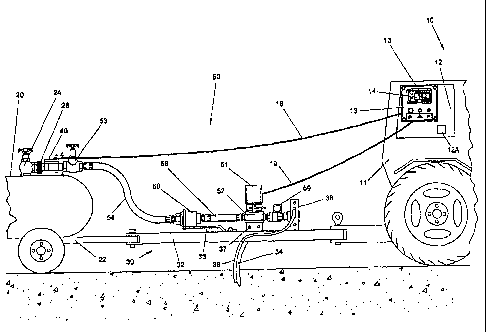
Referring to Figure 1, the present invention may include a vehicle 10 such as
a
tractor, a nurse tank 20, a tool bar 30, a flow meter 40, flow distribution
system 50 and
a flow regulator 52. Vehicle 10 includes a cab 11 with control station 12 and
a control
- 8 -
CA 02239315 1998-08-28
panel 13. The control station 12 includes a conventional analog or digital
engine
tachometer 12A and an application chart discussed subsequently. The tachometer
12A
may be linked to any suitable ground speed indicator device such as, for
example, the GPS
system also discussed subsequently. Referring to Figure 2, control panel 13
may include
a flow rate display 14, on/off button 15, an on/offindicator light 16 and a
two-way toggle
switch 17 for actuation of flow regulator 52. Line 18 runs from flow meter 40
to circuitry
within the control panel for flow rate display 14. Line 19 runs from the
circuitry toggle
switch 17 to gear motor 51 for actuating flow regulator 52. The circuitry
on/off button
may be connected to the tractor battery (not shown) through line 15A via the
cigarette
10 lighter (not shown).
The farmer may use an application chart to determine the NH3 flow rate
necessary
to achieve the desired application of NH3 per acre. An exemplary application
chart may
have an x axis representing pounds ofNH3 per acre and a y axis representing
vehicle speed
in miles per hour. The intersection of the x and y axis on the chart shows
values in gallons
15 per minute in liquid NH3. Each chart may be adapted for a particular length
of the tool
bar 30. Individual charts may be used for each of the variety of tool bar
swaths that are
available on the market. In a preferred embodiment, a chart is not required
for this
purpose, and the desired NH3 flow rate is determined by a computer in the
control panel
based on the information input by the farmer. The mode of the flow rate
display 14 can
be changed to display information stored in totalizers (not shown), wherein
one of such
totalizer is resetable.
Nurse tank 20 may be carried on its own frame 22. Nurse tank 20 is of a design
known in the art, and is normally fitted with a dip tube (not shown) which
runs to the
bottom of the tank 20 for drawing the NH3 from the tank 20, a withdrawal valve
24 fluidly
connected to the dip tube, and a pressure gauge (not shown). A speed nut or
hose
connection piece 26 is conveniently located on the discharge port of the
withdrawal valve
24.
Tool bar 30 is of a design well known in the art which is transported by
vehicle 10.
Tool bar 30 includes a frame 32 and a plurality of knives 34 for tilling the
soil. A portion
of the flow distribution system 50 described below is mounted on the tool bar
frame 32
with bracket 36 for safety coupler 56, and bracket 37 for flow regulator 52.
The number
of knives 34 and the swath of the tool bar 30 may vary.
- 9 -
CA 02239315 1998-08-28
Referring to Figures 1, 3 and 4, in a less preferred embodiment of the
invention,
the flow meter 40 may be a commercially available turbine meter calibrated for
NH3. The
rotor 42 is mounted in casing 46 by braces 43. Vanes 44 of rotor 42 are driven
by the
moving NH3 fluid. Casing 46 is adapted at one end for connection to a
connecting piece
of the flow distribution system 50, such as speed nut 26. Vanes 44 have a
magnetic tip
45. Casing 46 houses a magnetic pickoff 48 which lies in the radial plane of
rotor 42 and
is adapted for connection to line 18. Pulses are generated through line 18 by
induction
as rotor 42 spins. The trailing end of the flow meter 40 is connected to the
flow
distribution system 50. It is possible to place the flow meter 40 ahead of
withdrawal valve
24 or within the tank 20 by retrofitting currently available systems. This
would further
decrease the pressure drop prior to reading the flow rate, although such a
retrofitting is
expensive and typically is not desired.
The flow distribution system 50 may comprise any of a number of arrangements,
and the flow regulator 52 may be placed anywhere convenient downstream of flow
meter
40. Referring to Figures 1 and 5, two embodiments are shown. In addition to
the flow
meter, the flow distribution system typically includes a hose end valve 53, a
hose 54, a
safety coupling 56, flow line 58, control valve 52, and on/off valve 59, a
distributor 38 and
tubing 39 going to each knife 34.
Referring to Figure 1, a hose end valve 53 (as shown a globe shutoff valve)
connects to flow meter 40. Hose 54 runs to pull away safety coupling 56.
Because of the
toxic nature of NH3, pull away safety coupling 56 is required. The design of
pull away
safety coupling 56 is known to one of ordinary skill in the art and in
principle functions
similar to an air chuck. Such a safety coupling is a substantial flash point
for the
generation of vapor. Flow line 58 runs from pull away safety coupling 56 to
flow
regulator 52. An additional valve 59 may be placed in flow distribution system
50. This
valve 59 is an on/off valve and may be manually but is typically hydraulically
controlled.
The general design of distributor 38 is known to one of ordinary skill in the
art and
functions to distribute NH3 to tubes 39. The tubes 39 extend along the
framework 32 and
down to each of the knives 34 where the NH3 is distributed to the soil.
Figure 5 represents another embodiment of the flow distribution system 50
where
hose 54 stays with the nurse tank 20. The farmer may purchase or rent the
nurse tank 20
connected to the withdrawal valve 24, which is in turn connected to hose 54
which runs
to a breakaway coupling 56. The system as shown in Figure 5 includes a low
restriction
- 10 -
CA 02239315 1998-08-28
valve, such as the full opening ball valve 53, and a hose connection piece 26
spaced
between valve 53 and coupling 56. The turbine meter 40 is downstream from the
breakaway coupling 56. Flow line 58 runs from meter 40 to the next component
in the
flow distribution system 50, which may comprise either a flow regulator 52 or
a valve 59.
The present invention is effective for controlling the amount of NH3 to be
distributed to the soil. Referring back to Figure 1, as the NH3 is withdrawn
from the nurse
tank 20, it experiences nil pressure drop through the dip tube and a very
small pressure
drop through the withdrawal valve 24 (nurse tanks 20 are normally fitted with
a Y-pattetn
withdrawal valve having a "smooth" curve rather than a "hard" curve such as
that within
like a typical globe valve) and through the speed nut 26. The NH3 flowing
through the
flow meter 40 (which also has a very small pressure drop) is thus primarily
but generally
not totally in the liquid state. As the NH3 continues through the system, it
experiences
substantial pressure drop through the pull away safety fitting 56, an
additional pressure
drop through the flow line 58 and a varying pressure drop through the flow
regulator 52,
depending upon whether it is partially closed (large flash) or fully open
(smaller flash)
prior to flowing into the distributor 60. During each pressure drop, the NH3
flashes and
becomes more two phased.
Referring to Figure 5, the flow path is similar except the NH3 flows through
hose
54 prior to flowing through the hose end valve 53 and the flow meter 40. All
components
downstream of withdrawal valve 24 and upstream of flow meter 40 may be full
port, low
restriction devices or components, to induce a minimal pressure drop. Flow
sensing for
flow rate measurement may thus occur before substantial flashing of the NH3
occurs.
Flow meter 40 ideally may measure the flow rate when the NH3 is primarily a
liquid. As explained subsequently, however, some vapor will likely be present
in the flow
even if the meter 40 is positioned very close to the nurse tank. This vapor
causes a
significant error in the flow measurement from the meter 40, and is corrected
as discussed
below. The raw or uncorrected signal from flow meter 40 is transmitted to flow
display
14 where the operator reads a corrected flow rate measurement in gallons per
minute.
The operator then reads ground speed and determines how many pounds of
nitrogen per
acre are being distributed to the soil. The operator then adjusts his speed or
adjusts the
flow rate to control the amount of nitrogen being distributed to the soil.
As discussed above, vapor in the NH3 liquid causes a shift in the flow reading
and,
if not corrected for or removed, can lead to significant errors. A key feature
of the system
- 11 -
CA 02239315 1998-08-28
is the ability to correct for vapor in the liquid. To accomplish this, the
controller applies
a constant or fixed value compensation correction factor (to correct for vapor
in the
system at the meter 40) and a temperature compensation factor (to correct for
fluid
density variation as a function of fluid temperature) and then calculates the
actual flow
based upon these factors.
The first step in calculating the vapor compensation factor is to apply a
significant
amount of NH3 to determine the system error for a particular flow distribution
system.
Regardless of theoretical similarities, it has been found that this correction
signal is best
determined from actual tests conducted on each particular distribution system.
The vapor
compensation correction value remains a constant for that system. Before
applying the
first tank, the operator ensures that the Total Counter (total flow
measurement in gallons)
is cleared to zero. The Total Counter thus keeps track of the number of
gallons applied
as determined by the flow meter. When applying this first calibration tank, it
is important
to stop the NH3 application before the tank gets too low and excessive vapor
flows
through the meter.
A comparison of the controller Total Counter to the actual gallons utilized
provides the information required to determine the vaporization compensation
factor for
the particular system in use. In the following example, Initial Tank Weight In
was 4582
lbs and Final Tank Weight was 256 lbs, so that Total NH3 Used was 4326 lbs.
Assume
5.12 lbs per gallon for NH3, then the Total Gallons Used = 4326 = 5.12 = 845
gallons.
If the Total Counter shows 900 gallons used, the flow rate error is determined
by (900 -
845) = 900 = 0.061 and 0.061 x 100 =+6.1%. Meter Compensation thus is -6.1%
for this
flow distribution system, and this correction value is entered into the
controller.
The controller, mounted inside the tractor cab, allows the operator to monitor
and
adjust the NH3 flow rate. The controller also monitors the raw flow rate and
NH3
temperature to initially deternune the raw flow rate corrected for density due
to changing
temperature. The measured flow rate is then offset or corrected with the fixed
vaporization compensation factor for that particular flow system to compensate
for vapor
to determine the actual corrected flow. The actual flow is compared to the
desired flow
and adjustments are made to the control valve.
Control of the anhydrous flow rate may be done with a totally independent
system.
Flow regulator 52 may comprise a special rotating plug valve used for flow
control. This
flow control valve 52 may be actuated by a 12 volt dc high ratio gear motor 51
as shown
- 12 -
CA 02239315 1998-08-28
in Figure 1. On/offand directional control of the gear motor may be performed
in the cab
with the on/off button 15 and spring return reversing toggle switch 17. The
farmer
provides the link between the flow measurement system and the powered
regulator 52 of
the flow control system. Flow regulator 52 may be adjusted by two way toggle
switch 17
to "trim up" or "trim down" the valve. If the valve is fully open and the
farmer can't get
enough flow (typically when it's very cold), he must slow down to achieve the
desired
application rate.
The controller (control panel) can be upgraded to include a GPS receiver to
determine the tractor true ground speed. An accurate speed is critical in
maintaining the
exact desired flow rate and can significantly improve application accuracy.
The GPS
system measures true ground speed, maintains high accuracy at all speeds, and
is
unaffected by vibration, waving weeds, or field debris that interfere with
radar speed
systems. The GPS system is also simple to install and setup may be achieved at
a low
cost.
A Global Positioning System (GPS) is based on satellite ranging. A position on
earth is determined by accurately measuring the distance from a group of
satellites in
space. The distance to a satellite is determined by measuring how long a radio
signal takes
to reach the receiver. By using the distance measurement from a minimum of
four
satellites, and knowing the locations in space of the satellites, the GPS can
triangulate a
position on earth including altitude. To determine speed-over-ground, two
positions may
be measured exactly one second apart. The distance in feet between the two
positions is
the speed in feet per second. The control panel 13 displays the speed in miles
per hour.
When the controller 13 is first turned on, the system may perform several
internal
tests to verify that the equipment is functioning properly. The display will
alert the
operator of any possible problems. As part of the power on sequence, some of
the
operator programmable values may be read from the controller's non-volatile
memory and
briefly displayed to allow the operator to review the present settings. A GPS
antenna
(shown as 132 in Fig 9) may be mounted on the vehicle cab, and the GPS unit
may output
a signal which is received at connection 12B as shown in Figure 2. After
loading the
current settings from memory, the controller checks to see if a GPS receiver
is installed.
If a GPS signal is found, the controller will wait for the GPS to finish
downloading
information from satellites. This process may take from 20 seconds to 3
minutes
- 13 -
CA 02239315 1998-08-28
depending on how much information the GPS needs to download and how long the
controller has been turned off.
If no GPS signal is found, the fixed tractor speed may be loaded from memory
and
displayed on the controller screen. The fixed tractor speed may be used as the
vehicle
speed when the GPS is not installed or not working. If the controller is not
equipped with
a GPS for speed measurement, this is the speed that the operator may drive the
tractor.
With the GPS installed, the fixed tractor speed is commonly only used if the
GPS signal
is lost or the GPS fails. Tractor speed may be used to determine the flow rate
as well as
acres covered. To adjust the fixed tractor speed, the operator toggles the
SETUP switch
until the SET FIXED TRACTOR SPEED choice is displayed. For a known tool bar
width and desired application rate, the farmer can choose among many tractor
speeds and
flow rate combinations. When a tractor speed is chosen, it is then matched to
the flow
rate in GPM of NH3 liquid required to obtain the desired fertilization.
In the field, the control valve 52 is opened or closed from the cab 11 to
obtain the
required flow rate as observed on the display. If soil conditions or tank
pressure varies
significantly, the flow rate will change but can easily be adjusted back to
the desired rate.
Thus the farmer has continuous and verifiable control of the anhydrous
application. The
control valve 52 thus adjusts the flow to maintain a consistent application
rate. The valve
position may be controlled by a DC gear motor 51. A position indicator may be
used to
provide a quick visual indication of how far open or closed the valve is at
any time. The
controller is intended to make automatic adjustments to the valve to maintain
the desired
flow rate. The valve 52 can also be adjusted manually at any time by toggling
the flow
switch 17 on the controller up to increase the flow rate or down to decrease
the flow rate.
Using the flow switch 17 also switches the controller to manual control. In
manual, the
controller will not make automatic adjustments to the control valve. The
operator may
toggle CANCEL to return to automatic control. The control valve 52 is designed
for flow
control only, and is not designed to shut-off tight. The control valve 52 thus
should be
used in conjunction with a shut off valve.
The controller 13 can be setup to alarm if the flow drifts too far from the
desired
flow rate. If the rate error is greater than the ALARM SETPOINT, the
controller will
display a message prompting the operator that the flow rate is too high. If
the rate error
is less than the alarm setpoint, the display will alarm that the flow rate is
too low. Setting
the FLOW RATE ALARM to f0.0 GPM turns off the alarm feature. The RATE ERROR
- 14 -
CA 02239315 1998-08-28
ALARM may also help indicate when the nurse tank is running low and the dip
tube is
allowing excessive vapor to flow through the meter. This is an indication that
the tank is
near empty and should be replaced or filled. The shutoff valve 59 is used
downstream of
the control valve for on/off control during vehicle turns in the field.
A control cable connects the controller to the flow meter and the control
valve.
Weatherproof connectors may be keyed so that they can only be connected to the
correct
devices. The controller can be up to 35 feet from the flow meter and control
valve, and
the control valve is mounted near the flow meter. The flow meter and the
control valve
are typically screwed together.
In a preferred embodiment, a variable area flow meter replaces the turbine
meter
discussed above. Variable area meters generally measure flow by keeping the
pressure
drop through the meter constant while an orifice area is varied to match the
flow. A
variable area meter as disclosed herein is not easily damaged by vapor flow,
has few
moving parts, and is simple to use and maintain. The variable area meter is
also not
affected by upstream piping effects as are turbine meters, which typically
require a
minimum of 10 times the inlet pipe diameter of straight pipe before the meter
and 5 times
the pipe diameter of straight pipe on the meter outlet. Variable area meters
also tend to
be self cleaning. The velocity of the flow past the vane of the variable area
meter
preferably used in this invention and the freedom of the vane to move within
the meter
housing to clean itself prevents buildup of foreign material. The variable
area meter is
thus used to determine mass flow rate (pounds/hour) of NH3. Since the vane
responds to
changes in fluid density, the vane position in the meter will change with
changing fluid
density.
A simplified variable area meter 60 according to the present invention is
shown in
Figure 6. The orifice area is varied by moving a vane 62 through an internal
cavity 64
within the meter, so that the cross-sectional flow area changes as a function
of the vane
position with respect to the meter housing 66. The position of the vane is
directly related
to the flow rate. One method for measuring the position of the vane is to
extend the
rotating shaft which is connected to the vane through a seal in the meter
housing. The
shaft may turn a potentiometer (not shown) or may be connected directly to a
vane
position indicator. A variable area flow meter could thus be equipped with
such a
potentiometer to measure shaft rotation and thus vane position, thereby
providing a flow
rate signal to the controller 13. Passing the meter shaft through a seal to
exit the meter
- 15 -
CA 02239315 1998-08-28
housing is undesirable, however, for both safety and reliability reasons,
since ammonia gas
is very corrosive and the seal life is low. The seal can also add friction to
the rotating
shaft, thereby introducing error to the flow reading. The pressure rating for
this meter is
also limited due to the shaft seal. High pressure, such as 400 psi commonly
used for NH3
applications, would be difficult to achieve with this type of meter.
Another possible variable area meter, which could eliminate the seal, would
magnetically couple the vane through the meter housing. The magnets of the
magnetic
coupling technique may cause errors over time due to hysterisis. By
incorporating a
spring return feature with a magnetically coupled indicator, a flow meter more
appropriate
for NH3 use is obtained. There still exists a problem of converting the
measured position
of the vane to an electrical signal for telemetry to a controller which
regulates a flow
meter. A proposed method for doing this is to use a potentiometer. A primary
problem
with a potentiometer is that it adds friction which causes error to the flow
reading, since
some amount of torque is required to move the potentiometer element. The
potentiometer element also has a limited life since it wears during use.
Another proposed
method would be to use a Variable Displacement Transducer, or LVDT. This
device uses
a modulated transformer to detect position, adding no friction to the vane
shaft due to its
non-contact feature. An LVDT is very accurate and has long service life. LVDT
transducers are, however, expensive and require complicated electronic
processing and
calibration. This technology would add significant cost to the system and
would reduce
reliability due to increased complexity. A simple, precise, non-contact sensor
is thus
preferred that will detect the vane position and output a signal indicative
thereof to the
controller.
To overcome these problems, a hall effect sensor is preferably used to measure
the
vane position in the meter housing. The hall effect sensor or transducer
output is
responsive to the rotational position of a magnet mounted on the same shaft.
Rotation of
the magnet alters the flux density and thus the sensor output by changing the
resistance
of the sensor. This technique eliminates both the seal and friction induced by
a measuring
transducer. A hall effect sensor thus produces a voltage output proportional
to magnetic
field strength. The field seen by the sensor becomes negative as it approaches
the north
pole, and more positive as it approaches the south pole. This type of sensor
features
mechanical simplicity.
- 16 -
CA 02239315 1998-08-28
A ceramic magnet 68 as shown in Figure 6 is fitted on the vane shaft 70. The
magnet may be fixed to the vane shaft 70 so that at half flow the hall effect
sensor 72 is
directly between the north and south poles of the magnet. The meter body 66 is
designed
to allow the vane 62 to rotate 90 from no-flow to full-flow. The output of
the sensor 72
may be conditioned and transmitted back to the controller 13 as shown in
Figure 1 in a 4-
20ma format. The 4-20 milliamp format is popular in the industrial community
due to its
immunity to voltage cross-talk and changes in wire and connector resistance.
The flow
meter signal is converted to a voltage and is preferably digitized at the
controller 13. The
flow rate in GPM is calculated from the digitized voltage signal using an
equation fitted
to the characteristics of the meter housing, the vane and the spring force.
Figure 6 also
shows a suitable position for a temperature sensor 74 to output a density
correction signal
to the controller 13. The sensor 74 is preferably positioned within the cavity
64 of the
meter housing so that vaporization correction and density correction are made
on
substantially the same fluid as it passes through the meter.
The ring magnet 68 is magnetized across the vane shaft. As the magnet rotates,
the gap between the magnet and the sensor 72 is kept constant, but a varying
output is
produced as a result of changing flux of the magnet based on its rotational
position with
respect to the sensor 72. This provides a non-intrusive method of accurately
measuring
the flow meter vane position through the meter housing without adding
resistance to the
vane shaft. The magnet may be formed from a ceramic or a rare earth material.
The
magnet has an arcuate body with an exterior surface defining a portion of a
circle, thereby
maintaining the desired constant gap between the magnet and the sensor 72. The
meter
housing 66 is designed to allow the vane 62 to rotate approximately 90 from
no flow to
full flow. The sensor 72 may be positioned to be in the center of the magnet
poles at 50%
flow.
Figure 7 illustrates a preferred embodiment of a paddle shaft or vane assembly
76
for use in a variable area flow meter according to the present invention.
Paddle shaft
assembly 76 includes the bearing housing 78 and upper and lower plastic
bearings 80 for
guiding rotation of paddle shaft 82. Vane arm 84 is securely mounted on the
shaft 82 and
carries a paddle 86 which serves as the cross-sectional flow area defining
member within
the meter, as discussed above. A spacer 88 separates the arm 84 from the
magnet 90,
which is functionally and operationally the same as the magnet 68 shown in
Figure 6. A
nut 92 secures the magnet 90 in place by engagement with a threaded portion 93
of the
- 17 -
CA 02239315 1998-08-28
shaft 82. A coil spring 94 or other suitable biasing member is fixedly mounted
on the
paddle shaft for biasing the paddle 86 in the no flow position. The lower
shaft bearing
member 96 is provided at the lowermost end of the rotatable shaft 82, and
plastic bearing
80 is provided between member 96 and the lowermost fitting 98. The fitting 98
may be
sized for receipt within a suitable cavity in the meter housing, and another
coil spring (not
shown) may be used for exerting an upward force on the fitting 98 to retain
the
components in place. The conventional 0-ring 99 is provided to center the
magnet 90 on
the shaft 82.
Figure 8 illustrates a preferred embodiment of a variable area flow meter 130
according to the present invention, which includes the paddle shaft assembly
76 shown in
Figure 7. The variable area meter 130 includes a meter housing 102 and a cover
plate 104
which are mechanically coupled by suitable bolt members 106. An 0-ring 108
provides
for sealed engagement between the housing 102 and the cover 104. A pair of
screws 110
fix the bearing housing of the vane shaft assembly 76 to the meter housing
102.
A temperature probe assembly 112 is shown for sensing the temperature of the
fluid as it passes through the internal cavity in the housing 102. 0-ring 114
provides for
sealed engagement between the probe assembly 112 and the housing 102. A PC
circuit
board 116 is sized to fit within cavity 117 in the housing 102, with a pair of
nylon spacers
118 electrically isolating the circuit board 116 from the metal housing 102.
The circuit
board 116 may include one or more computer chips for performing the
calculations
discussed above, and for outputting appropriate display signals to the
operator and control
signals to the regulator. Circuit board 116 is retained in place by a pair of
conventional
screws 120. A cover plate 122 is mounted to the meter body 102 by screws 126,
and an
0-ring 124 provides for sealed engagement between the cover plate 122 and the
body
102. A wire seal strain relief 128 is provided for fitting within port 130 in
the body 102.
The ring magnet 68 provides a low cost and accurate method of measuring the
vane position in the variable area meter. By not requiring shaft seals, the
meter housing
can be designed to withstand both corrosive or hostile fluids and high
pressures. The vane
shaft may easily rotate on two plastic bearings.
The preferred variable area flow meter of this invention uses a unique non-
intrusive and low cost method of measuring vane position which relates to flow
rate. The
flow meter ideally meets the following requirements: (1) the flow meter is
compatible
- 18 -
CA 02239315 1998-08-28
with the corrosive properties of the fluid; (2) the meter is capable of
surviving the high
velocity vapor flow with no significant degradation to the meter performance;
(3) the flow
meter may be economically manufactured with a 400 psig pressure rating; (4)
due to the
flashing properties of liquid, there is a low differential pressure developed
across the meter
to minimize vapor; (5) the flow meter has excellent repeatability and low
drift over a large
operating temperature range; (6) contaminants in the fluid, such as rust or
dirt, do not
affect or degrade the performance of the meter; (7) the meter may easily
monitor a flow
range from 3 to 30 GPM of the measured liquid, such as anhydrous ammonia; and
(8) the
flow meter is simple to use, install and service. The variable area meter 60
as shown in
Figures 8, 9 and 10 meets the above design requirements. The preferred flow
meter
improves reliability and safety over existing flow meters used in NH3
distribution systems.
To compensate for the changing density of NH3 with temperature, the meter 60
as shown in Figure 6 is equipped with a digital temperature probe 74. The
controller 13
reads the fluid temperature and applies a temperature correction algorithm to
the
measured flow. Temperature correction charts located in operation manuals may
be used
to enable the operator to determine the flow set point in gallons per minute.
To make the
system more friendly, the procedure to determine the desired flow rate is
preferably
automatically performed by the controller 13. The user enters the TOOL BAR
WIDTH,
TRACTOR SPEED, and DESIRED APPLICATION rate in pounds per acre. The
computer within the controller 13 thus calculates the flow set point, first by
making the
temperature correction based on the sensed temperature, and then making the
vaporization correction based on the system test discussed earlier. All values
are saved
in memory so if only one of the values (tractor speed for example) needs to be
changed,
the other values are already set. The measured flow is displayed along with
the flow
deviation (FLOW POINT minus SET POINT). This makes it easy to determine if the
flow needs to be increased or decreased to maintain the desired application
rate. A
positive deviation indicates the flow rate is too high and the operator needs
to make
adjustments to the control valve 52.
A flow rate alarm feature may also be included, in the system of this
invention.
The flow deviation may be compared to an alarm set point. If the deviation is
higher or
lower than the alarm trigger setting for more than a preferred period of time,
e.g., 5
seconds, a message will flash on the display indicating that the flow rate is
either too high
or too low. This prompts the operator to make adjustments to the rate control
valve 52
- 19 -
CA 02239315 1998-08-28
using the flow adjustment switch 17 on the controller 13. A large deviation
error could
be an indication that the nurse tank is near empty, or that the flow meter is
measuring
excessive/no liquid vapor flow from the nurse tank.
Figure 9 depicts a preferred embodiment on an NH3 distribution system
according
to the present invention. Components similar to those depicted in Figure 1 are
labeled
with the same reference numerals. Anhydrous ammonia flows from the tank 20
through
the withdrawal valve 24, and then through a hose connection piece 26, ball
valve 53 and
flexible hose 54. Safety pull away coupler 56, such as that disclosed in U.S.
Patent No.
5,320,133 or pending Application Serial Number 09/016,505 filed January 30,
1998, is
mounted on the bracket 36 secured on the tool bar 30. Flexible flow line 58
extends from
the safety pull away coupler 56 to the flow meter 130, with the control valve
52 operated
by gear motor 51 being immediately downstream from the meter 130 which is
mounted
on bracket 37. Shut off valve 59 is provided in between the control valve 52
and the flow
distributor manifold 38, and a representative flow tube 39 extends from the
manifold 38
to each of the knives 34.
A controller 12 similar to that previously discussed is provided on the cab 11
of
the vehicle. Figure 9 shows a GPS antenna 132 connected to the controller 12
by line
133. If desired, the electronics for the GPS system may be included within the
controller
12. A 12-volt DC power line 15A is provided from the vehicle battery (not
shown) to
power the controller. Line 19 extends from the controller to the gear motor 51
of the
regulator 52, while line 18 extends from the flow meter 130 to the controller.
The present invention may be used to control flow in liquid systems other than
anhydrous ammonia. Alternative liquids may include anhydrous ammonia and one
or
more other liquids. The method and apparatus disclosed herein are especially
useful for
controlling the flow of liquids which have a low boiling point. The system of
the invention
could also be used to control the distribution of herbicides, pesticides, or
weed control
liquids. The variable area flow meter may be used to measure the flow rate of
various
liquids in real time and thereby control the flow rate of the liquid through a
flow line in
real time. The meter is, however, particularly well suited for measuring the
flow rate of
a low temperature vaporization liquid, such as anhydrous ammonia, butane or
propane.
The preferred embodiment of the invention has been shown and described above.
It is to be understood that minor changes in the details, construction and
arrangement of
- 20 -
CA 02239315 1998-08-28
the partes and steps may be made without departing from the spirit or scope of
the
invention as described.
- 21 -