Note : Les descriptions sont présentées dans la langue officielle dans laquelle elles ont été soumises.
CA 02239416 1998-06-02
METHOD OF COMMUNICATING DATA THROUGH A SLICKLINE
OR OTHER SINGLE CABLE SUSPENSION ELEMENT
Field of Invention
The present invention relates to actuation of down hole well tools and the
transmission of information and commands between the tool and surface
equipment particularly by means of mechanical signals conducted through a wire
or
slickline suspension element.
Background of Invention
In the operation of petroleum wells if is at times necessary to position a
tool for data gathering or other purposes at a vertical location in the well
and then to
actuate the tool. It is desirable to monitor the data acquired by the tool
while the
tool remains in the well. It is often necessary to reposition the tool to a
different
location down hole and acquire additional data without removing the tool from
the
well.
In some systems actuation of the tool is by means of a pressure sensor
triggered when pressure down hole exceeds a predetermined level. In other
systems an accelerometer with a time delay is used to activate the tool when
no
motion has been detected for a predetermined period of time. Other systems use
established profiles in the well to set and actuate the tools. However, such
systems
are only useful when profiles are present in the completed well. In such
systems
the tool becomes supported in the recessed profile with the resulting weight
shift
actuating the tool as shown, for example, in U. S. Patent No. 5,361,838 for
slickline
casing and tubing joint locator apparatus and associated method.
Some systems use electrical or electronic signals transmitted by insulated
wire conductors to send data between the tool and surface equipment. Such
CA 02239416 1998-06-02
_2_
systems may be costly, require special tools and specially trained personnel
and
may require extra storage space which often is at a premium.
In another system actuation of down hole tools is accomplished by
inducing motion in the wire line or slickline as shown in U. S. Patent No.
5,456,316
Downhole Signal Conveying System. The tool monitors motion for predetermined
patterns. Detection of a predetermined pattern actuates performance of a
desired
function. The tool may then transmit stored information to the surface by
means of
a mechanical signal embodied in a shift of the resonant frequency of the cable
without using a conducting cable.
Summary of Invention
According to the present invention the well tool is equipped with a latch
mechanism allowing the tool to be anchored at any desired point in the well
tubing.
The latch mechanism may be activated to anchor the tool in place by any of the
systems or methods previously referred to. With the tool thus anchored the
tension
on the wire or slickline can be manipulated from the surface by increases or
decreases from the normal of "hang weight" tension exerted on the wire. The
tool
senses a coded pattern of tension changes and is programmed to appropriately
operate or respond. After actuation of the tool by cable tension changes, data
is
gathered and transmitted to the surface by the tool in a coded pattern of
tension
changes produced by a mechanism within the tool in response to the data
acquired.
By adding a "bias tension" above the "hang weight" tension on the wire,
communication by tension changes becomes more reliable.
CA 02239416 1998-06-02
-3-
Brief Description of the Drawings
The specific objects and advantages of the invention and its salient
features will become apparent from the following detailed description when
read
with reference to the accompanying drawings wherein:
Figure 1 illustrates the basic surface equipment of the type normally used
to perform slickline work on a well as modified to accommodate the present
invention;
Figure 2 shows a load cell suitable for use in the present invention to
measure line tension as connected between the slickline lower pulley and the
well
head structure;
Figure 3 shows one form of wire tensioning device suitable for use with
the present invention;
Figure 4a is a diagrammatic illustration of the down hole tool of the
present invention locked in place in the well; and
Figure 4b is a diagrammatic illustration of the down hole tool of the
present invention using a spring-powered type of alternative tensioning
mechanism;
Figure 4c is a diagrammatic illustration of the down hole tool of the
present invention using a pneumatically-powered type of alternative tensioning
device;
Figures 5, 6 and 7 are time versus tension graphic plots illustrating
tension shift signals of the type used to transmit data and operating
instructions
between surface equipment and the down hole tool according to the present
invention.
CA 02239416 1998-06-02
-4-
Detailed Description of a Preferred and Other
Embodiments of the Invention
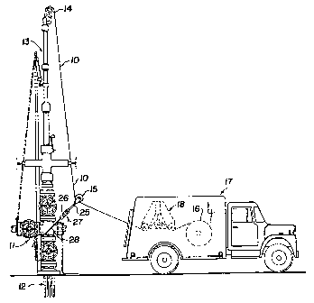
Referring now to Figure 1 there is shown diagrammatically basic surface
equipment of the type often used to service and collect data from an oil/gas
well as
modified for use with the present invention. The equipment uses a single non-
conducting wire, cable or slickline 10 to lower a service tool through the
well head
structure or "Christmas tree" 11 into the well hole 12. The equipment may
comprise
a stanchion structure 13 attached to the well head 11 providing access to the
well
bore 12 for inserting, raising, lowering and communicating with a well tool
(not
shown).
Wire 10 attached to and supporting the well tool extends out of the
stanchion 13 over the upper pulley 14 around the lower pulley 15 anchored to
the
well head and a storage reel 16 housed in a service truck (or other structure)
17.
The reel 16 may be mechanically or hydraulically driven in the usual manner to
raise and lower the tool in the well hole 12. Any suitable power source may be
used such as an electric motor or diesel engine.
Also provided in the service truck 17 is a surface end wire tensioning
device designated generally as 18. As shown in more detail in Figure 3 the
wire
tensioning device 18 may take the general form of or be combined with a three
pulley odometer if the wire odometer is not otherwise a part of reel 16 and
its drive
mechanism.
As illustrated in Figure 3 the wire tensioning device may comprise a pair
of pulleys 19 and 20 with their axles journalled respectively in fixed legs 21
and 22
CA 02239416 2004-03-11
-5-
extending from the main frame of the tensioning device, not shown. A third
pulley
23 is mounted for rotation on a moveable powered arm 24. Arm 24 is driven
preferably hydraulically in a vertical plane to move pulley 23 up or down
relative to
pulleys 19 and 20. Thus, with the wire line 10 threaded through the tensioning
device 18 passing under pulleys 19 and 20 and over pulley 23 the tension on
wire
is changed when the tensioning arm 24 is moved up or down.
The amount of tension in the slickline 10 and any change thereof is
transmitted through pulley 15 and the arm 25 on which it is mounted to sensor
27
that may be used to anchor the lower pulley 15 to the well head 11 such as
with
chain 28 or other means. Tension sensor 27 may be of any suitable type but
preferably is a load cell or link 26 which may be any of the various suitable
types
available from M/D TOTCO instrumentation of Cedars Park, Texas and others.
Alternatively, the tension sensor 27 may take the form of a load pin inserted
in
place of the pulley shaft of pulley 15 or of the pulley shaft of pulley 14.
Figure 2 shows another form of tension sensor 27 suitable for some
applications of the present invention. In Figure 2 the tension sensor 27 is a
fluidic
element 35. In element 35 pressure changes across piston 29 in upper and lower
cylinders 30 and 31, respectively, are signaled through output elements 32 and
33
to pressure sensors not shown but well know in the industry.
The various necessary operating controls, motor controls, signal
processing devices, all of which may be of types well known to those skilled
in the
art, are or may also be housed in the service truck 17.
CA 02239416 1998-06-02
-6-
Turning now to Figure 4a there is diagrammatically illustrated a typical
down hole tool 40 of the type useful in the present invention. The tool 40 is
shown
suspended by slickline 10 within the well tubing string or casing 41. Within
the tool
housing 42 are various transducers, detectors and measurement devices and
signal processors (represented at 43) used to collect well data. Also present
in the
tool are the elements used to control the tool, transmit and receive data and
control
signals between the tool 40 and surface equipment in the service truck 17.
These
elements include a power source such as battery 44, motor 45, tensioning
mechanism 46, a latch mechanism 47, a load cell 48 to detect line tension and
a
signal encoder/decoder/control electronics element 49 to translate data and
instruction signals in the form of line tension variations. All of these
elements of this
inventive combination comprise devices of the type well known in the industry
as
useful in down hole tools.
In any down hole data gathering or well treatment operation the basic
steps comprise inserting the tool into the well, positioning the tool within
the well to
carry out the desired operation, initiating and terminating or detecting
automatic
termination of each operation to be performed, moving the tool to another
position
within the well for further operations and/or removing the tool from the well
when all
of the desired operations have been performed.
According to the present invention the communications between surface
equipment and the tool down hole that are necessary to initiate and control
the
operation of the tool and to recover information from the tool are provided by
variations in the tension of the single slickline wire or cable holding the
toot.
CA 02239416 1998-06-02
_7_
The tool 40 is attached by means of the tensioning mechanism 46 to the
wire 10 through load cell 48. The tensioning mechanism 46 may comprise a ball
screw or other suitable device to lengthen or shorten the linkage between the
wire
line 10 and the tool frame 50 to which it is attached. Other examples of power
sources to change wire line tension include a pretensioned spring device as
illustrated in Figure 4b or a stored pressure fluid source as shown in Figure
4c.
In the tensioning device 46 used in Figure 4b a series of spring
mechanisms 61, 62, and 63 are held in compression within a containing element
64. Line 10 is anchored to plate 65 below the spring element 61-63 and
slidable
within container 64. Spring mechanism 61, 62, and 63 are held in compression
by
solenoid-operated latches 66, 67, and 68 respectively. The latches 66-68 are
controlled by the control electronics element 49.
When a step increase in tension is to be provided, bottom latch 66 is
operated to release the compression of spring element 61 to apply tension
force
through plate 65 to line 10. Operation of latch 67 to release spring 62
applies
additional tensioning force to line 10. Operation of latch 68 to release
spring 63
adds still more tensioning force to line 10.
At any time or after all of the spring elements have been released the
spring elements can be reset by using the storage reel 16 drive mechanism to
pull
line 10 and move plate 64 upward to again compress the springs and then by
appropriate operation of the latches to hold them in compression.
The tension increases can then again be sequenced.
CA 02239416 1998-06-02
_$_
In the tensioning device 46 illustrated in Figure 4c a compressed gas
source, tank 70, holds a supply of nonflammable operating gas, such as
nitrogen.
The lower end of line 10 is connected to piston 72 movable within the
pneumatically
sealed cylinder 73. When it is desired to increase the tension in line 10 the
control
electronics element 49 operates valve 71 to allow a metered amount of
pressurized
gas to flow through line 74 and 75 into the upper chamber 76 of cylinder 73.
The
resulting downward pressure on piston 72 increases the tension on line 10.
The amount of tension increase is programmed into and controlled by the
electronic element 49. The tension increase is controlled by the length of
time valve
71 is held open relative to the gas pressure in the source tank 70, the size
of the
pneumatic cylinder 73 and the lines 74 and 75.
The gas in chamber 76 can be released by opening an exhaust port in
valve 71 after a programmed predetermined time period subsequent to each
tension increase to provide a series of timed signals of a constant or varying
amplitude.
Alternatively, the system can be operated to provide a series of step
signals by admitting additionally pressurized gas into chamber 76 in a coded
pattern without releasing gas already in the chamber.
Alternatively, the sysetm can be operated to provide a series of step
signals by admitting and removing pressurized gas into and out of the chamber
76
in a coded pattern.
The wire line tension and changes therein are communicated to the
electronic package 49 via electrical cable 51.
CA 02239416 2004-03-11
_g_
In operation the method of the present invention is carried out as follows.
The tool 10 is lowered through the well tubing string by playing out the
slickline from the supply reel 16 in the service truck. The location of the
tool down
the well is monitored and the tool is positioned by any of the well known
means not
requiring electrical connection to the surface. Such a system is described in
U. S.
Patent No. 5,361,838 issued November 8, 1994 to Marion D. Kilgore for
Slickline
Casing and Tubing Joint locator Apparatus and Associated Methods .
Once the tool has been positioned at the desired depth location in the well
it is anchored in place in the tubing string. This may be accomplished by
latching
the tool into a profile that is part of the tubing string as is well known.
Another way
of anchoring or latching the tool 40 in position in the string 41 is by
activating slips
52 shown as motor driven in Figure 4. Activation of the latching mechanism 47
may
be by timers, counters, accelerometers or other mechanisms of types well known
located in the tool housing 42.
Once the tool is latched in the well string 41, tension on the slickline 10
can be manipulated. First tension is increased by tensioning device 18 at the
surface to establish a certain tension value above the "hang weight" tension
on the
line as the "zero reference." Thereafter, patterned tension changes can be
introduced into the slickline by tensioning device 18 at the surface to
initiate and/or
control test procedures to be carried out by the tool. Tension change patterns
are
also applied by the tensioning mechanism 46 in the tool down hole to signal
operation progress or to transmit data from tests performed.
CA 02239416 1998-06-02
-10-
The "hang weight" tension on the slickline when the tool reaches its
desired depth or position cannot be precisely predicted or controlled because
of the
varying conditions such as a deviation of the tubing string 41 along its
length and/or
rubbing of the slickline 10 on the inside of the tubing 41 itself or against
accumulations such as scale, paraffin, debris in the tubing, or against other
devices
in the well. Nevertheless, it has been found that with a wire length/tool
depth of
10,000 feet, a 0.092 inch diameter wire must be stretched approximately 62
inches
to produce a tension increase of 100 pounds. While wire stretches in this
range
can be accomplished relatively easily with surface equipment, they are
difficult to
achieve by mechanisms in the tool down hole. Thus, instructions and operating
signals from the surface to the tool may be encoded as relatively large
sometimes
sustained changes in tension from the established reference such as shown for
example by the curve 55 in Figure 5.
Alternatively, data or other signals from tool to surface may take a digital
form such as a series of relatively small changes in the tension that convey
information by their frequency, as shown on curve 56, by their relative
spacing, as
shown on curve 57, their polarity such as illustrated by curve 58 in Figure 6
or other
coding schemes. The tension changes may be only about 1/10 to 1/20 the
magnitude of those induced by the surface tensioning device. Since a high rate
of
transmission is not required for data, a ball screw or any other relatively
small and
slow device is suitable for use within the tool as tensioning mechanism 46.
Further,
it is possible if desirable to superimpose data signals on reference signals
of
CA 02239416 1998-06-02
-11-
various levels as a means of identifying the type or source of data as
illustrated for
example by curve 59 in the graph of Figure 7.
Thus, there has been disclosed a method of communicating data and
instruction signals between surface equipment and a down hole well tool
through
variations in the tension in a non-electrical wire or slickline used to
support and
transport the tool within the well.
The foregoing detailed description is to be clearly understood as being
given by way of illustration and example only; the spirit and scope of this
invention
being limited solely as set forth in the following claims.
Claims: