Note : Les descriptions sont présentées dans la langue officielle dans laquelle elles ont été soumises.
CA 02240164 1998-06-10
WO 97/25553 PCTlFI97/00006
Gear with bearing arrangement
R
The invention concerns a gear.
From the prior art, minimization of the bearing play is known by using a
separate
transfer mechanism, a screw device, by whose means the play is minimized by
shifting the bearing race in the lateral direction. In the prior-art
solutions, the
shifting of the bearing race takes place expressly by means of a separate
positioning
actuator.
In the present patent application, attempts have been made to find a solution
for the
IS problem of bearing play, in particular in a gear in which the gear
comprises a high-
speed shaft and a low-speed shaft, in which connection the high-speed shaft is
fitted
to rotate the low-speed shaft. The low-speed shaft is mounted from both sides
of the
toothed rim by means of rolling ball bearings. In a prior-art solution of said
sort, in
particular with increasing speeds, problems arise in the bearings of the low-
speed
shaft. In particular in paper machine drives, when temperatures vary, the
bearing
plays must be adequate in order that a reliable operation of the bearing could
be
guaranteed under all conditions of operation. In a gear, it is possible to
speak of a
Ioad effect point at the point at which the high-speed shaft is in contact
with the low-
speed shaft. In a normal situation of loading, attempts are made to minimize
the
forces applied to the bearings by balancing the gear by means of a torque
support
from a suitable point on the outside frame constructions. When the halancinu
is
successful, the bearing fully relies on its plays and is, in such a case,
susceptible of
oscillation. In such a case, outside impulses produce an increased risk of
damage in
the bearing means. When the gear is used in a paper machine drive, high
changes in
the thermal load arise on the grooved ball bearings placed at both sides of
the
gearwheel of the low-speed shaft, which changes further result in a
requirement of
a large play. When the play becomes larger, some of the rolls glide along the
race
CA 02240164 2004-09-16
2
track, in which case bearing damage and bearing wear are increased. According
to
the present invention, the service life of the bearings of the low-speed shaft
has been
increased by using a separate spring device in the lateral shifting of the
bearings.
The spring device is fitted so that its springs act upon the bearings of one
of the
bearing races, so that the spring force is applied outwards from the area
between the
bearings and upon the outer bearing race. The bearing race is mounted by means
of
a glide fitting on the frame of the bearing housing, and by means of the
springs the
bearing race is shifted outwards in the construction. In this way the bearing
play is
eliminated and the rolling members are shifted into contact with their bearing
races,
both with the inner bearing race and with the outer bearing race. When the
rolling
members are shifted into contact with the inner bearing race, the force acts
upon the
gearwheel shaft connected with the inner bearing race, and the inner race of
the
other bearing is now further shifted, in its turn, so that the shifting takes
place
towards the vertical central axis Y of the bearing. Thus, by means of the same
spring device, the plays are eliminated from two sets of bearing means, both
from
one side and from the other side of the gearwheel.
In accordance with one aspect of the present invention, there is provided a
gear, which
comprises a first shaft and on it a first gearwheel, which is in engagement
with a
second gearwheel mounted on a second shaft, the second shaft comprising first
and
second bearings at both 'sides of the second gearwheel between a frame and the
second shaft, on which bearings the second shaft is fitted to revolve, wherein
the gear
comprises at least one spring, which is fitted to act with a force upon an
outer race of
rolling members of the first bearing, between the circumferential face of
which the
outer race and the gear frame or a connected part there is a glide fitting, in
which
connection said force effect is transferred further through the rolling
members of the
first bearing to an inner race of the first bearing and further to the second
bearing
placed at the opposite side of the gearwheel, whereby the play in the first
and second
bearings placed at both sides of the gearwheel, between the rolling members
and
bearing races is eliminated.
CA 02240164 2004-09-16
2a
The invention will be described in the following with reference to some
preferred
embodiments of the invention illustrated in the figures in the accompanying
draw-
ings, the invention being, however, not to be confined to said embodiments
alone.
Figure 1 illustrates the situation occurring at the load effect point in a
bearing
construction.
Figure 2A is a sectional view of a gear construction in accordance with the
present
invention.
Figure 2B is a separate illustration of a ring with spring sockets in
accordance with
the present invention.
CA 02240164 1998-06-10
WO 97/25553 PCT/FI97/00006
3
Figure 2C is a sectional view taken along the line I-I in Fig. 2B.
Figure 2D is an illustration in part of the fixing of the ring with spring
sockets to the
gear frame.
Figures 3A...3D show different bearing constructions which are suitable for
use in
a gear in accordance with the present invention and in a spring loading in
accordance
with the present invention.
Fig. 1 illustrates the situation caused by the load effect point in particular
in bearing
constructions of large, S00 mm ... 800 mm, diameter. In the prior-art
situation
shown in Fig. 1, the load acts upon the point P. The direction of effect of
the force
is indicated by the arrow F 1. In such a case, the play is at the minimum at
the side
opposite to the load {point O1) and at the maximum at the side of the load
(point 02}.
The rolling members in the bearings glide (at the point 02) and do not revolve
along
their race track faces. This further results in wear and possibly in bearing
damage.
The situation is made worse, in particular with large bearing diameters (cø
500 mm
... ~ 800 mm), especially by the fact that the bearing play must be relatively
large
in order that the variations occurring in the thermal load could be taken into
account.
When the play is large between the rolling members and the bearing rings or
races
in the bearing construction, a situation is also possible in which, when the
gear is
well balanced by means of a torque arm, oscillations further cause resonance
in the
bearing members. In such a case, the susceptibility of the bearings to damage
is
increased further.
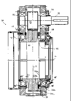
Fig. 2A illustrates a gear in accordance with the present invention. The gear
10
comprises a frame 11. The drive is introduced into the gear through the shaft
12.
The shaft 12 is mounted from both sides of its gearwheel 13 by means of
bearing
means 14 and 15. The high-speed shaft 12 is fitted to rotate the shaft I6
comprising
the gearwheel of larger diameter. The shaft 16 comprises the gearwheel 17 and
the
bearing means 18 and 19 at both sides. The bearing means 18 and 19 can be
grooved ball bearings, tapered roller bearings or angular-contact ball
bearings. They
CA 02240164 1998-06-10
WO 97/25553 PCT/FI97/00006
4
are preferably single-row bearings, which means that the bearing members are
placed in one row only between the inner race and the outer race of the
bearing.
Each bearing 18,19 comprises rolling members 20a1,20a2..., such as rollers,
balls ~
or equivalent, between its races, i.e. the inner race and the outer race. The
rolling
members run in the inner circumferential grooves in their bearing races.
According to the invention, the construction is provided with spring means,
which
comprise a ring 2I with spring sockets, and in the different spring sockets
22a1,
22a2... in the ring 21 there are the springs 23a1,23a2..., preferably spiral
springs.
The ring 21 with spring sockets is attached to the side face llal of the gear
frame
11 by means of screws 24a1,24a2... Thus, the ring 21 with spring sockets is
placed
between the side face lla and the side face Di of the gear wheel 17 placed on
the
shaft 16. Thus, the springs 23a1,23a2... of the ring 21 with spring sockets
are fitted
to act with a force outwards from the vertical centre line (Y line) of the
bearing
construction (force arrows in the direction Ll and in the direction of the
axis X1 of
rotation). The construction is fitted in such a way in relation to the outer
race of the
bearing 18 that the ring 21 with spring sockets is fixed by means of screws
24at,
24a2. . . to the frame I I above the side face C 1 of the outer race 18' of
the bearing
so that the springs 23aI,23a2... press the race 18' with a force and act upon
its front
face. The circumferential face C1 of the outer race 18' of the bearing 18 is
fitted
with a glide fitting on the frame l I of the gear. Then, the bearing race I8'
can be
displaced in the direction of the axis of rotation (X1 axis) of the gear so
that the
rolling members 20aI,20a2... of the bearing can be brought into contact both
with
the side face of the inner rolling groove of the outer race I8' of the bearing
and with
the side face of the inner rolling groove of the inner race 18" of the
bearing. Thus,
as is shown in the figure, the force F acts in the direction Li and shifts the
rolling
members 20a1,20a2 of the bearing means into contact both with the side of the
rolling groove of the outer race 18' of the bearing I8 and with the side face
of the
rolling groove of the inner race 18" of said bearing. Thus, the plays between
the
rolling members 20a1,20a2... of the bearing and the bearing races 18',18" have
been
eliminated. Thus, the force effect is transferred from the outer race I8'
further to the
inner race 18" and further to the shaft 16, which is also shifted in the
direction Li.In
CA 02240164 1998-06-10
WO 97125553 PCT/FI97/00006
this connection, the force acts upon the inner race 19" of the second bearing
means
19, and thereby the play is also eliminated in said second bearing 19 of the
shaft. It
is an essential feature that the shaft 16 is floating, i.e. freely moving in
its axial
direction (direction Xl). The bearing 19 is fixed to the gear so that both the
inner
5 race 19" of the bearing 19 is fitted on the shaft 16 with a press fitting,
i.e.
stationarily, and the outer race 19' of the bearing I9 is mounted stationarily
on the
connected gear construction 11, preferably likewise with a press fitting.
However,
since the shaft I6 can be displaced in the direction of the central axis and
axis of
rotation (X 1 axis) of the shaft 16, by means of the force F it is also
possible to shift
the rolling members 20a1,20a2 of the bearing against the side faces of the
inner
rolling grooves or rolling tracks of their bearing races 19' and 19" . Thus,
in this
connection, by means of the springs 23ai,23a2..., it is possible to eliminate
the play
also in respect of the second bearing means.
Thus, it is not at all self evident in what area of the bearing means the
force F of the
springs 23a1,23a2... is fitted to act, or in what direction in relation to the
vertical
central axis (Y axis) of the gear. In the construction in accordance with the
inven-
tion, the springs 23ai,23a2... act upon two sets of bearing means at both
sides of the
gearwheel 17 on the shaft 16 in the gear 10. According to the invention, when
the
force F is effective away from the Y axis in the direction of the central axis
of
rotation (X axis) of the gear, the bearing means are brought into a what is
called 0
position, in stead of the other alternative, i.e. the X position. In the so-
called 0
position, the rolling axes of the bearing means are placed circumferentially,
and, on
the other hand, in the X position the rolling axes of the bearing means are
placed so
that the rolling axes intersect each other in the centre point of the
journalling. From
the point of view of the stability of the journalling, said so-called 0
position is
preferable. In the construction in accordance with the invention, when the
spring
means act outwards from the vertical centre Iine (Y line) of the gear and when
the
~ spring means act expressly upon the outer bearing race, the so-called 0
position is
accomplished in the journalling. The vertical centre line Y passes through the
middle
of the gearwheel 17 perpendicularly to the axis X1 of rotation.
CA 02240164 1998-06-10
WO 97/25553 PCTIF'I97/00006
6
Fig. 2B is a separate illustration of the ring 2I with spring sockets as a
side view.
Fig. 2C is a sectional view taken along the line I-I in Fig. 2B. The ring 21
with
spring sockets is fitted in the area between the bearing means 18 and the
gearwheel
17 so that the spring sockets 22a1,22a2... in the ring 21 with the spring
sockets are
opened outwards, in which case the springs 23a1,23a2... fitted in the spring
sockets
22a1,22a2..., preferably spiral springs, cup springs, or equivalent, are
fitted to act
with a force F upon the outer race 18' of the bearing means, which outer race
is
fitted to the gear or to a connected construction with a glide fitting. The
ring 21 with
spring cavities includes holes 25a1,25a2..., through which the fastening
screws
24a1,24a2... are passed and threaded further into the threaded holes provided
in the
side face llal of the frame 11 of the gear. The springs 23a1,23a2... are
dimensioned
so that normal thermal expansion does not produce an excessive additional Ioad
on
the bearings but, on the other hand, the spring force is sufficient to prevent
gliding
(stopping) of the bearing rollers in a situation of operation.
Fig. 2D shows an alternative of fixing the ring with spring sockets to the
frame by
means of screws 24a1,24a2, which have been passed through the holes
25a1,25a2...
into the threaded holes 26a1,26a2... in the frame.
Fig. 3A shows a conventional grooved ball bearing, which can be used in the
journalling in accordance with the present invention and whose outer race can
be
acted upon by means of the spring loading device of the invention. In Fig. 3A,
the
point of effect and the direction of effect of the spring force are indicated
by the
arrow F. Thus, the bearing means 20a1,20a2... are shifted into contact both
with the
side face fl of the race track el of the outer race 18' of the bearing and
with the side
face f2 of the race track e2 of the inner race 18" of the bearing. Thus, the
play is
eliminated between the bearing members 20at,20a2... and the related bearing
races
18' and 18". In Fig. 3C a tapered roller bearing is shown, to which the
invention is
also applicable. Fig. 3B shows an angular-contact ball bearing, for which the
invention is also suitable, as it iS for the double-row bearing shown in Fig.
3D. By
means of the spring rim, forces of about 3000...5000 N are transferred to the
outer
CA 02240164 1998-06-10
WO 97/25553 PCT/FI97/00006
7
ring of the bearing, i.e. to the outer bearing race, when the bearing diameter
is in
the range of ~ 500 mm ... 800 mm.