Note : Les descriptions sont présentées dans la langue officielle dans laquelle elles ont été soumises.
CA 02240490 1998-06-12
W O 97/21526 PCT~US96/19889
FOOD PRODUCT SLICER HAVING AN INTERLOCK M~CHANISM
BACKGROUND OF THE INVENTION
The present invention relates, in general, to a food
product slicer and, in particular, to a ~ood product slicer
having an interlock device which allows the food product
carriage tray and supporting leg to be removed for cleaning
only when the gauge plate i~ closed and prevents opening o~
the gauge plate while the carriage tray and leg are removed
from the slicer.
Commercial food product slicers are widely utilized
as rapid and effective means of slicing meat, cheese,
vegetables and other food products. These machines commonly
include a motor driven circular slicing blade having a
peripheral cutting edge and a carriage which passes the food
product over the blade. To adjust the thickness of the slice,
these machines include a gauge plate which is adjusted in
relation to the slicing blade to set the slice thickness.
Because of the nature of these machines, food and fat debris
often build up on the gauge plate and carriage. For that
reason, both the product carriage and the gauge plate must be
frequently cleaned to maintain the slicer.
To facilitate cleaning of the carriage and gauge
plate of a conventional ~ood product slicer, slicers have been
designed which have a carriage that can either be removed from
the housing or be pivoted away from the cutting deck of the
machine. Once the carriage is moved away from the body of the
slicer, the edge of the slicing blade near the gauge plate
becomes exposed if the gauge plate is in the open position.
This exposed slicing blade, because it is razor sharp, can cut
the operator if the operator were to inadvertently contact the
blade edge.
To prevent the operator from contacting the edge of
the blade, food product slicers have been designed with
CA 02240490 1998-06-12
WO 97nl526 PCT~US96/19889
interlock devices which prevent the carriage from being
removed from the slicing machine unless the gauge plate is
closed, i.e., adjusted to a position approximately coplanar
with the slicing blade, and which provide coverage of the
blade edge while the carriage tray is moved away from the
slicer housing. For example, United States Patent No.
4,541,319 to Maurer, et al. describes an interlock device for
a meat slicing machine. The carriage of this meat slicer can
be pivoted away from the machine when the gauge plate is
closed. The carriage articulates a slider member. When the
gauge plate is open, a stop on the slider member engages a
counter stop member on the carriage thereby preventing the
carriage ~rom being pivoted.
SUMMARY OF THE IMVENTION
The present invention is directed to an interlock
mechanism for a food product slicer which prevents the
carriage from being removed from the slicer housing unless the
gauge plate is closed. The slicer comprises a housing, a
gauge plate, a food product carriage, an interlock mechanism
and other con~entional parts. The slicing blade is circular
and is mounted on a drive shaft. The drive shaft is driven by
a motor housed in the housing. The gauge plate is adjusted
relative to the slicing blade to set the thickness of a
particular slice. The gauge plate is adjusted by an
adjustment means which moves the gauge plate from a closed
position, at which the gauge plate is about coplanar with the
edge of the blade, to an open position, at which food product
can be sliced.
The food product carriage is mounted for
reciprocation in the housing. The food product carriage
comprises a base, a support which is removably mounted on the
base and a tray. The carriage support is pivotally mounted on
the base in a mounting head. The mounting head is lin~ed to a
plunging element which is biased inwardly toward the housing
--2--
CA 02240490 1998-06-12
W O 97/21526 PCT~US96/19889
by a spring. The plunging element translates with movement of
the carriage support between a retracted position and an
extended position at which the carriage is removable from the
housing for cleaning.
To limit access to the slicing blade while the
carriage support is moved away ~rom the housing and the gauge
plate is opened, the slicer incorporates an interlock
mechanism. The interlock mechanism prevents the carriage
support from being pivoted away from the housing by preventing
translation of the plunging element when the gauge plate is in
an open position. When the gauge plate is in the closed
position, the interlock mechanism allows the carriage to be
pivoted away from the housing and prevents the gauge plate
from being opened.
The interlock mechanism includes an interlock bar,
which extends along a portion of the path of reciprocation of
the carriage, and an interlock plate. The portion of the path
of reciprocation of the carriage not covered by the interlock
bar is covered by the interlock plate. The interlock plate is
pivotally mounted on the housing such that it is movable from
a position at which it blocks translation of the plunging
element to a position at which it allows translation of the
plunging element. The interlock plate cooperates with the
adjustment mechanism such that when the gauge plate is in the
open position, the interlock plate is in position to prevent
translation of the plunging element. When the gauge plate is
in the closed position, the interlock plate moves to a
position at which it does not impede translation of the
plunging element.
In a preferred embodiment, the adjustment mechanism
includes a cam and a knuckle formed on the interlock plate.
The knuckle interacts with the cam such that when the gauge
plate is in the open position, the knuckle maintains the
interlock plate in position to block translation of the
CA 02240490 l998-06-l2
W O 97/21526 PCTrUS96/19889
plunging element. When the gauge plate is closed, the knuckle
interacts with a recess in the cam to allow the interlock
plate to move to a position at which it does not block
translation of the plunging element.
To remove the carriage support from the sliclng
machine, the gauge plate must be closed and the carriage must
be moved to the end of the housing on which the adjustment
knob is mounted. This end of the apparatus is commonly known
as the operator end of the apparatus. The carrlage support
and tray can then be removed from the carriage by rocking the
carriage support away from the housing and lifting the
carriage support from the carriage. When the carriage support
i8 removed from the slicer, an interlock is established which
prevents the gauge plate from being opened unless the carriage
support is replaced in the mounting head and the head is
pivoted toward the housing. As the carriage support is being
removed, the plunging element is translated beneath the
interlock plate. When the plunging element is underneath the
interlock plate, the interlock plate is biased into engagement
with the means for adjustment so that it prevents the means
for adjustment from being moved. A spring, which abuts the
plunging element and the casting of the carriage base, exerts
an inward axial force toward the housing on the plunging
element. The force exerted by the spring is strong enough to
prevent the plunging element from being withdrawn from
underneath the interlock plate by hand. Once the carriage
support is replaced on the housing, the leverage generated by
moving the carriage into position on the housing causes the
plunging element to be removed from the interlock position.
In the preferred embodiment, as stated above, the
knuckle on the interlock plate engages a recess in the cam,
which is part of the means for adjustment. When the plunging
element is beneath the interlock plate, the knuckle is biased
toward and into contact with the recess. The positioning of
the knuckle in the recess prevents the cam from being moved.
CA 02240490 1998-06-12
W O 97/21526 PCTAJS96/19889
Once the plunging element is removed from beneath the
interlock plate, the cam can be moved to adjust the gauge
plate. As the cam is being moved, the knuckle moves out of
contact with the recess to ride along the peripheral surface
of the cam. As the knuckle rides on the peripheral surface of
the cam, the interlock is maintained in a position at which it
blocks translation of the plunging element.
In an alternate embodiment, the adjustment mechanism
of the food product slicer can include an alternate cam which
provides for easier adjustment of the gauge plate. The
alternate cam requires the operator to turn the cam for more
than one revolution before the gauge plate is located at its
position ~arthest from the slicing blade. To allow the
alternate cam to function with the interlock of this
invention, a groove is formed in the peripheral sur~ace of the
alternate cam. A pin extending from an arm, which is
pivotally mounted on the interlock plate, rides in the groove
and prevents the knuckle on the interlock plate from engaging
the recess on the alternate cam when the gauge plate is in an
opened position. When the gauge plate is in the closed
position, the pin moves into an aperture at one end of the
groove in the alternate cam which allows the knuckle to move
into the recess which, in turn, allows the interlock plate to
move out of a position which blocks translation of the
plunging element.
In still another alternate embodiment of this
invention, the slicer interlock may additionally include a
slicing blade deactivation mechanism which shuts off the motor
for the slicing blade when the carriage is removed. The
switch mechanism includes an actuator, one end of which is
mounted in the plunging element. When the plunging element is
moved to a position beneath the interlock plate, the actuator
contacts a switch which is mounted on a bracket extending from
the housing. When the interlock is activated, the actuator
CA 02240490 1998-06-12
W O 97/21526 PCT~US96/19889
contacts the switch to interrupt the power supply to the
slicing blade motor to cause the slicing blade to stop
rotating.
The novel features of this invention are set out in
the appended claims. The invention, itself, however, both as
to its construction and method of operation, is best
understood from the following detailed description when read
in conjunction with the accompanying drawings.
BRIEF DESCRIPTION OF THE DRAWINGS
Fig. 1 is a perspective view of a food product
slicer which employs the interlock mechanism of this
invention;
Fig. 2 is a cross-sectional view of the interlock
mechanism of the food product slicer when the gauge plate is
in an open position;
Fig. 3 is a cross-sectional view of the slicer with
the interlock mechanism when the gauge plate is in the closed
position;
Fig. 4 is an enlarged cross-sectional view of the
mounting head and plunging element of the interlock mechanism;
Fig. 5 is a bottom perspective view of the interlock
mechanism of the food product slicer including a cutaway view
of the carriage base;
Fig. 6 is a perspective view of the cam and
interlock plate of the alternate embodiment of the invention;
CA 02240490 1998-06-12
W O 97/21526 PCT~US96119889
Fig. 7 is a cross-sectional view of an alternate
em~odiment of the interlock mechanism, which includes the
slicing blade deactivation mechanism, when the gauge plate is
in an open position ; and
.
Fig. 8 is a cross-sectional ~iew of an alternate
em~odiment of the interlock mechanism, which includes the
slicing blade deactivation mechanism, when the gauge plate is
in the closed position.
DETAI~ED DESCRIPTION OF THE I~rVENTION
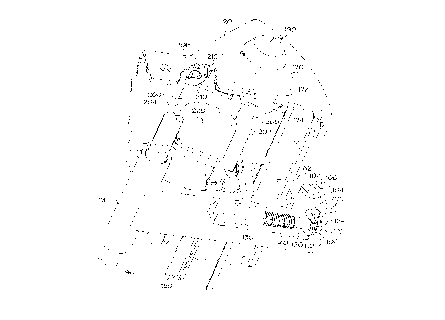
Fig. 1 presents a perspective view of a typical food
product slicer 10 which employs the interlock mechanism of
this invention. Slicer 10 includes a housing 20, a slicing
blade 30, a gauge plate 40, a food product support carriage
50, a cover plate 60 and an adjustment knob 190. Slicing
blade 30 and gauge plate 40 are mounted on housing 20 of
slicer 10. Slicing blade 30 is journalled to a drive shaft
tnot shown) and is rotated by a motor ~not shown) which is
mounted in housing 20. Gauge plate 40 is adjustable toward
and away from slicing blade 30 by a means for adjustment (not
shown) to set the thickness of a food product slice. Food
product carriage 50 is mounted for reciprocation on housing 20
so that it can move food product to ~e sliced over blade 30.
Carriage 50 can be reciprocated either manually by the machine
operator or driven by a motor in the case of an automatic
slicer. Food product carriage 50 includes a carriage support
52 and a tray 54 mounted on support 52. Cover plate 60 is
removably mounted on slicer 10 over blade 30.
Gauge plate 40 is moveable axially with respect to
the plane of blade 30 to establish the thickness of a slice.
The thickness of a particular slice of a food product is
determined by the distance between slicing blade 30 and gauge
plate 40. Gauge plate 40 is moved toward and away from the
surface of slicing blade 30 by a conventional means for
CA 02240490 1998-06-12
W0 97/21~;26 PCT/US96/19889
adjustment, which is not shown. Adjustment knob 190 is
rotatably mounted on housing 20 and is used to operate the
means for adjustment to move gauge plate 40.
When gauge plate 40 is adjusted to establish a slice
thickness, it is referred to as being "open." Gauge plate 40
can also be located at a "closed" position at which the slice
thickness setting is zero and gauge plate 40 covers that
portion of the periphery of blade edge 32 which is usually
exposed during a cutting operation. In the closed position,
gauge plate 40 is typically either coplanar with or slightly
raised above the plane of slicing blade 30. Gauge plate 40
covers approximately one-third of peripheral edge 32 o~
slicing blade 30 when set at the closed position. The
remainder of the circumference of peripheral edge 32 may be
covered by a ring guard (not shown) which covers the edge of
blade 30 not covered by gauge plate 40.
Fig. 2 presents a cross sectional view of the
interlock mechanism when the gauge plate is in an open
position. As shown in Fig. 2, carriage 50 comprises a first
carriage support 52, a base 70 and a second leg 71. Bracket
72 is formed in base 70. Bracket 72 pivotally receives
mounting head 100 which is cylindrical. Mounting head 100
includes a square shaped mouth 102 and legs 104 and 106. Legs
104 and 106 can best be seen in Fig. 5, which is discussed in
detail below. Legs 104 and 106 are located opposite mouth 102
and extend downwardly from mounting head 100. Carriage
support 52 includes a foot 56 which is elidably received by
mounting head 100 to mount carriage support 52 in base 70.
Leg 71 extends upwardly ~rom base 70 and is typically shaped
to conform to the contour of housing 20. In its end opposite
base 70, leg 71 includes an aperture 48. Carriage support 52
may optionally include ~astener 58 which is threaded into
aperture 48 and used to secure carriage support 52 on leg 71
so that carriage support 52 cannot be moved away from food
producer slicer 10. In its upper surface, a slot 82 is formed
CA 02240490 1998-06-12
W O 97121526 PCTAJS9~/19889
in bracket 72. Slot 82 has a width slightly larger than that
o~ ~oot 56 o~ carriage 50 and a width approximately equal to
or slightly greater than that of mouth 102 o~ mounting head
100. Extension 112 is formed from the casting o~ base 70 and
provides support ~or mounting head 100.
Base 70 of carriage 50 is mounted for reciprocation
on track 80 and bar 90. Track 80, which has a ~-shaped cross
section, and bar 90, which has a circular cross section,
extend the length o~ housing 20. Base 70 slides on bar 90 by
means of a bearing 74. Wheel 76 is carried on base 70 and
rides on track 80. As carriage 50 reciprocates, carriage 50
is carried on track 80 and bar 90 by means of wheel 76 and
tubular slide 74, respectively. Although track 80 is
described herein as having a rectangular cross section and bar
90 is described herein as having a circular cross section, one
skilled in the art will appreciate that track 80 and bar 90
can have any cross section which ~acilitates operation o~ the
slicing machine o~ this invention.
As can also be seen in Fig. 2, mounting head 100 is
linked to a screw 120 which threadedly engages a plunging
element 130. Plunging element 130 is mounted for
reciprocation in slot 84 in carriage base 70. Spring 140
engages a shoulder 138 in the casting of~base 70, at one end,
and plunging element 130 at its other end.
Fig. 2 also presents views of cam plate 170 and
interlock plate 200. Cam plate 170 has a peripheral surface
172. Recess 174 is formed in peripheral surface 172 of cam
plate 170. Interlock plate 200, which is discussed in detail
below, is reciprocally mounted in housing 20. Interlock plate
200 is mounted on the housing by brackets 210.
Fig. 4 presents an expanded cross sectional view of
the mounting head and linkage portions of the interlock
mechanism of this invention which is illustrated in Fig. 2.
CA 02240490 l998-06-l2
WO~7/21526 PCTAUS96/1988g
As shown in Fig. 4, mounting head 100 is rotatably mounted in
bracket 72 in base 70. Mouth 102 slidably receives ~oot 56 of
carriage support 52. Base 70 has a slot 84 machined therein.
As stated above, plunging element 130 is slidably mounted in
slot 84 in base 70. Plunging element 130 can have any cross
sectional shape which cooperates with the operation of this
invention. Preferably, plunging element 130 has a rectangular
or square cross section. Plunging element 130 has a first end
134 and a second end 136. A threaded aperture 132 iS machined
into flrst end 134 of plunging element 130. Screw 120 is
threadedly mounted in threaded aperture 132 in plunging
element 130. Screw 120 includes a head 124, body 126 and a
neck 122 which is located between head 124 and body 126.
Spring 140 engages shoulder 138 in the casting of base 70 of
carriage 50 at one end and plunging element 130 at a second
end.
Fig. 5 presents a view of the underside of ~ousing
20 and a cutaway view of carriage base 70. As can be seen in
Fig. 5, pins 108 and 110 extend from legs 104 and 106,
respectively, to couple mounting head 100 to neck 122 of screw
120. The coupling arrangement between pins 108 and 110 and
screw 120 allows mounting head 100 to rotate in bracket 72
without disconnecting pins 108 and 110 from neck 122 during
the rotation of mounting head 100.
As can also be seen in Fig. 5, cam plate 170 is
journalled to adjustment knob 190. Adjustment knob 190 moves
the adjustment mechanism, not shown, which moves gauge plate
40 axially in relation to slicing blade 30 to determine the
thickness of a resulting food slice. Movement of knob 190 in
a first direction increases the thickness of the slice by
causing gauge plate 40 to move away from slicing blade 30 and
movement of adjustment knob 190 in a second direction
decreases the thickness of the slice by causing gauge plate 40
to move toward slicin~ blade 3Q. When adjustment knob 190 is
moved to the zero slice thickness setting, gauge plate 40 iS
--10--
CA 02240490 1998-06-12
W O 97/21~26 PCT~US96/19889
moved to a position at which it is coplanar with slicing blade
30 or slightly raised above the surface of slicing blade 30 to
prevent access to the edge of slicing blade 30.
Interlock bar 150 can also be seen in Fig. 5. As
shown in Fig. 5, interlock bar 150 is mounted in housing 20
and extends over a portion of the path of displacement of
carriage 50. Interlock bar 150 can have a square, rectangular
or L-shaped cross section. Although described herein as
having a square, rectangular or L-shaped cross section,
interlock bar 150 may have any shaped cross section which
would cooperate with the interlock mechanism of this invention
and prohibit the translation of plunging element 130.
Interlock plate 200 can also be seen in Fig. 5. As
shown in Fig. 5, interlock plate 200 is rotatably mounted on
the inside of housing 20. Interlock plate 200 is mounted such
that it covers the remainder of the path of displacement of
carriage 50 which is not covered by interlock bar 150.
Interlock plate 200 includes a first end 202 and a second end
204. Legs 206 extend outwardly from second end 204 of
interlock plate 200. Interlock plate 200 is pivotally mounted
on housing 20 by means of brackets 210. Legs 206 engage
brackets 210 which slidably engage housing 20 at one end and
are fastened into position at their other ends by fasteners
which engage apertures 212. A spring (not shown) biases
interlock plate 200 toward and into contact with cam plate
170.
In a preferred embodiment, interlock plate 200
includes a knuckle 208 which extends from first end 202 of
interlock plate 200 and rides along the peripheral edge of cam
plate 170. Knuckle 208 rises from first end 202 of interlock
plate 200 a distance sufficient to malntain first end 202 of
interlock plate 200 in a position collinear with interlock bar
150 as knuckle engages cam plate 170. Interlock plate 200 may
optionally include a center aperture 220. Center aperture 220
CA 02240490 l998-06-l2
W O 97/21526 PCT~US96/19889
can be formed in interlock plate 200 to provide clearance ~or
the adjustment mechanism of gauge plate 40, if necessary.
To facilitate cleaning of slicer 10, food product
carriage 50 can be removed from housing 20. To remove
carriage 50 for cleaning, adjustment knob 190 is moved to the
zero slice thickness setting which moves gauge plate ~0 to the
closed position. Once gauge plate 40 has been closed,
carriage support 52 can be moved away from housing 20. As
carriage support 52 is being moved away from housing 20,
mounting head 100 rotates in bracket 72. As mounting head 100
rotates in bracket 72, pins 108 and 110 in legs 104 and 106
move screw 120 forward by pushing body 126 of screw 120 toward
housing 20 of slicer 10. When screw 120 is moved forward, it
forces plunging element 130 toward interlock plate 200.
As shown in Fig. 3, at the zero slice thickness
setting, i.e. when gauge plate 40 is in the closed position,
knuckle 208 on interlock plate 200 is received in recess 17~
on cam plate 170. The movement of knuckle 208 into recess 174
permits the spring (not shown) to pull interlock plate 200
toward housing 20 moving interlock plate 200 to a position at
which it is no longer collinear with interlock bar 150 and a
clearance is provided beneath interlock plate 200 which allows
second end 136 o~ plunging element 130 to pass beneath plate
200.
When second end 136 of plunging element 130 extends
beneath plate 200, mouth 102 in mounting head 100 is moved to
a position at which mouth 102 is aligned wlth slot 82 in
carriage base 70. To prevent mounting head 100 from over-
rotating and to ensure that mouth 102 properly aligns with
slot 82, the casting of base 70 includes an abutment 112 which
engages legs 104 and 106, respectively, of mounting head 100.
When legs 104 and 106 contact abutment 112, mounting head 100
is prevented from ~urther rotation. The contact o~ legs 104
and 106 with abutment 112 aligns mouth 102 with slot 82. Once
-12-
CA 02240490 1998-06-12
W O 97/21526 PCTnUS96/19889
mouth 102 is aligned with slot 82, carriage support 52 can
then be lifted vertically to remove ~oot 56 from mouth 102 in
mounting head 100. ~arriage support 52 can then be
di~connected from carriage base 70 and carriage 50 and slicer
10 can be cleaned.
While carriage support 52 is removed for cleaning of
slicer 10, gauge plate 40 cannot be moved from the zero slice
thickness setting to expose cutting blade 30. As can be seen
in Fig. 3, the extension of second end 136 of plunging element
130 below interlock plate 200 prevents interlock plate 200
from moving away from housing 20. This, in turn, prevents
knuckle 208 from dislodging ~rom recess 174 on cam plate 170
which prevents cam plate 170 from being moved by ad]ustment
knob 190. If cam plate 170 is prevented from moving, then
adjustment knob 190 and, subsequently gauge plate 40, cannot
be moved from the zero slice thickness setting. Spring 140
biases plunging element 130 beneath interlock plate 200 to
prevent the interlock device ~rom easily disengaging while
carriage support 52 is removed from housing 20. Spring 140
provides sufficient biasing force to maintain second end 136
of plunging element 130 beneath interlock plate 200 until
carriage support 52 is replaced onto slicer 10.
Once carriage support 52 is replaced onto base 70
and second end 136 of plunging element 130 is retracted ~rom
beneath interlock plate 200, gauge plate 40 can then be moved.
To return carriage 50 to a position at which slicer 10 can be
operated, foot 56 must first ~e reinserted into mouth 102 in
head 100. To remove second end 136 of plunging element 130
from beneath interlock bar 150, the operator must apply
sufficient force to overcome the biasing force of spring 140.
Because of the force o~ spring 140, mounting head 100 and
plunging element 130 can only be moved when carriage support
52 has been replaced on the slicer 10. As carriage support 52
is rotated toward housing 20 of slicer 10, mounting head 100
rotates in bracket 72. As mounting head 100 rotates, plunging
-13-
CA 02240490 l998-06-l2
W 097/21~26 PCT~US96/19889
element 130 is removed from beneath interlock plate 200 when
pin~ 108 and 110 in legs 104 and 106 on head 100 pull screw
120 laterally away from the inside of housing 200. Once
carriage support 52 has been replaced, carriage support 52 can
be secured into position on leg 71 by threading knob 58 into
aperture 48.
Once plunging element 130 is removed from beneath
interlock plate 200, cam plate 170 can be rotated by
adjustment knob 190 to dislodge knuckle 208 from recess 174 by
overcoming the biasing force placed on interlock plate 200 by
the spring. Once the biasing force of the spring is overcome,
knuckle 208 iS disengaged from recess 174 in cam plate 170 and
moved to ride on peripheral edge 172, as described above. Cam
plate 170 and, subsequently, ad~ustment knob 190 can then be
moved.
When slicer 10 is in use and gauge plate 40 iS in an
open position, carriage support 52 and tray 54 cannot be
removed from slicer 10. As stated above, knuckle 208 rides on
the peripheral edge 172 of cam plate 170, which is shown in
Fig. 2. As knuckle 208 rides on peripheral edge 172 of cam
plate 170, knuckle 208 maintains interlock plate 200 in a
position such that first end 202 iB collinear with interlock
bar 150. If the operator attempts to move carriage support 52
away from housing 20 while interlock plate 200 is collinear
with interlock bar 150, second end 136 of plunging element 130
will abut either interlock bar 150 or interlock plate 200.
The interference between plunging element 130 and either
interlock bar 150 or interlock plate 200 occurs because both
interlock bar 150 and interlock plate 200 do not afford second
end 13 6 O~ plunging element 130 enough clearance to pass
beneath themselves and move to an extended position. If
second end 136 of plunging element 130 can not move to an
extended position, then foot 56 of carriage support 52 cannot
be removed from mouth 102 in mounting head 100 because mouth
102 cannot align with slot 82 in bracket 72. The alignment of
-14-
CA 02240490 1998-06-12
W O 97t21526 PCT~US96/19889
mouth 102 with slot 82 i~ not possible when plunging element
130 is retracted, thus removal of carriage support 52 from
mounting head 100 is prevented.
To facilitate adjustment of gauge plate 40, slicer
10 may be outfitted with an alternate cam arrangement which
decreases the amount of torque the operator must apply to
adjustment knob 190 to cause the adjustment mechanism to move
gauge plate 40. With this alternate cam arrangement, which is
shown in Fig. 6, cam plate 270 must be rotated more than one
complete turn by adjustment knob 190 before gauge plate 40 is
moved to its farthest position from slicing blade 30. With
this alternate cam arrangement, the interaction of interlock
plate 200 with cam plate 270 must be altered to allow cam
plate 270 to complete more than one turn before the interlock
mechanism is engaged.
Fig. 6 presents a perspective view of the alternate
embodiment of cam plate 270 and interlock plate 200. Cam
plate 270 has a peripheral surface 272 into which a recess 274
has been formed. As can be seen in Fig. 6, a groove 276 is
formed into the peripheral surface 272 of cam plate 270.
Preferably, groove 276 encircles the peripheral surface 272 of
cam plate 270 for more than one turn of cam plate 270. Groove
276 terminates at one end in a first end 278 and terminates at
its other end in aperture 280. As groove 276 approaches
aperture 280, the depth of groove 276 gradually increases to
equal that of aperture 280. Aperture 280 is positioned on cam
plate 270 such that the position of aperture 280 is ~ixed with
respect to the position of recess 274. The positioning of
recess 274 and aperture 280 are fixed in relation to each to
allow the modified interlock plate 200, as described below, to
function in combination with cam plate 270.
In this alternate embodiment, arm 222 ic pivotally
mounted at second end 204 of interlock plate 200. A pin 224,
which travels in groove 276, extends from one end of arm 222
CA 02240490 1998-06-12
W O 97/21526 PCTAJS96/19889
to prevent knuckle 208 from engaging recess 274 in the
peripheral surface 272 of cam plate 270 while gauge plate 40
is in an open position. Pin 224 is maintained in position in
groove 176 by the biasing force provided by the spring (not
shown) which biases interlock plate 200 toward housing 20.
AS pin 224 travels in groove 276, it maintains
interlock plate 200 in a position at which it blocks
reciprocation of plunging element 130 and prevents knuckle 208
~rom moving into recess 274 on the peripheral surface 272 of
cam plate 270. When gauge plate 40 is moved to its fully
opened position, pin 224 is at first end 278 of groove 276.
At this position, interlock plate 200 iS positioned so that it
blocks reciprocation of plunging element 130. As adjustment
knob 190 is turned to rotate cam plate 270, pin 224 travels in
groove 276 around peripheral sur~ace 272 oE cam plate 270.
When gauge plate 40 is moved to the closed position, pin 224
engages aperture 178. When pin 224 engages aperture 280,
knuckle 208 can move to engage recess 274. As described
above, when knuckle 208 engages recess 274, interlock plate
200 moves to a position at which it does not block
reciprocation of plunging element 130.
Once plunging element 130 has been retracted from
beneath interlock plate 200 by replacing carriage 50 into
slicing machine 20, as described above, gauge plate 40 can be
adjusted by means of knob 190. ~s adjustment knob 130 is
turned, knuckle 208 disengages from recess 274. As knuckle
208 moves out of recess 274, pin 224 is lifted from aperture
280. Once pin 224 contacts groove 276, knuckle 208 is
prevented from contacting recess 274 and interlock plate 200
is moved to a position at which first end 202 iS collinear
with interlock bar 150. The remainder of the workings of the
interlock mechanism are as described above.
In an alternate embodiment, food product slicer 10
may include a slicing blade deactivation mechanism 300. This
mechanism 300 is shown in detail in Figs. 7 and 8. AS shown
-16-
CA 02240490 1998-06-12
W O 97/21526 PCT~US96/19889
in Flg. 7, plunging element 130 has a siot 146 ~ormed in
second end 136. Deactivation me~hanism 300 comprises an
actuator 302, having a first end 304 and a secorLd end 306, and
a swltch 310. First end 304 o:E actuator 302 is mounted in
slot 146 in plunging element 130. To accommodate actuator
302, a second slot 86 is machined into base 70 of carriage 50.
A bracket 312 is mounted to and extends ~rom housing 20.
Switch 310 is mounted on one end of bracket 312. Switch 310
comprises a contact 314 and a body 316. Contact 314 is
reciprocally mounted on switch body 316 and spring biased away
from body 316 by a spring which is not shown. As also shown
in Fig. 7, when plunging element 130 is retracted, actuator
302 does not engage switch 310.
As shown in Fig. 8, when second end 136 of plunging
element 130 is extended below interlock plate 200 as des~ribed
above, actuator 302 engages switch 310. When switch 310 i~3
engaged, the power supply to the motor which rotates slicing
blade 30 is interrupted and the ~notor is deenergized causing
slicing blade 30 to stop rotating. To engage switch 310,
actuator 302 is moved toward switch 310 by extending plunging
element 130, as described above. When plunging element 130
reaches a position beneath interlock plate 200, second end 306
of actuator 302 engages contact 314 of switch 310. The
activation of switch 310 then causes the power supply to the
slicing blade motor to be interrupted. Once the power to the
motor is interrupted, slicing blade 30 is shut off and the
opportunity for the operator of food product slicer 10 to come
into contact with a moving slicing blade 30 is reduced.
In this embodiment, actuator 302 must be withdrawn
from contact with switch 310 before slicing blade 30 can be
activated. To withdraw actuator 302 from contact with switch
310, plungin~ element 130 is retracted from beneath interlock
plate 200, as described above. As plunging element 130 is
retracted, second end 306 of actuator 302 is withdrawn from
contact with contact 314 of switch 310. Once second end 304
--17--
CA 02240490 l998-06-l2
W 0 97/21526 PCT~US96/19889
o~ actuator 300 is withdrawn from contact 314, the power
supply to the slicing blade motor is no longer interrupted.
To reactivate the slicing blade, the operator must reactivate
the main power supply switch (not shown) for slicer 10.
One skilled in the art will appreciate that switch
mechanism 300 can be employed with either embodiment o~ the
slicing machine 10 described above. Although switch mechanism
300 is shown in Figs. 7 and 8 as being employed with cam plate
170, switch mechanism 300 works e~ually as well with cam plate
270 which is shown in Fig. 6.
Having described the invention in detail, it will be
apparent that numerous variations and modi~ications are
possible without departing ~rom the spirit and scope o~ the
invention as defined by the following claims.
What is claimed is:
-18-