Sélection de la langue

Search

Sommaire du brevet 2240599 

Énoncé de désistement de responsabilité concernant l'information provenant de tiers

Une partie des informations de ce site Web a été fournie par des sources externes. Le gouvernement du Canada n'assume aucune responsabilité concernant la précision, l'actualité ou la fiabilité des informations fournies par les sources externes. Les utilisateurs qui désirent employer cette information devraient consulter directement la source des informations. Le contenu fourni par les sources externes n'est pas assujetti aux exigences sur les langues officielles, la protection des renseignements personnels et l'accessibilité.

Disponibilité de l'Abrégé et des Revendications

L'apparition de différences dans le texte et l'image des Revendications et de l'Abrégé dépend du moment auquel le document est publié. Les textes des Revendications et de l'Abrégé sont affichés :

  • lorsque la demande peut être examinée par le public;
  • lorsque le brevet est émis (délivrance).
(12) Brevet: (11) CA 2240599
(54) Titre français: CABLE AERIEN ET ENSEMBLE DE PINCE DE TENSION
(54) Titre anglais: AERIAL CABLE AND TENSION CLAMP ASSEMBLY
Statut: Périmé et au-delà du délai pour l’annulation
Données bibliographiques
(51) Classification internationale des brevets (CIB):
  • H02G 07/05 (2006.01)
  • G02B 06/48 (2006.01)
(72) Inventeurs :
  • SUTEHALL, RALPH (Royaume-Uni)
  • ARMITAGE, SAM (Royaume-Uni)
  • DAVIES, MARTIN VINCENT (Royaume-Uni)
(73) Titulaires :
  • PRYSMIAN CABLES & SYSTEMS LIMITED
(71) Demandeurs :
  • PRYSMIAN CABLES & SYSTEMS LIMITED (Royaume-Uni)
(74) Agent: KIRBY EADES GALE BAKER
(74) Co-agent:
(45) Délivré: 2003-12-09
(22) Date de dépôt: 1998-06-12
(41) Mise à la disponibilité du public: 1998-12-13
Requête d'examen: 2001-02-09
Licence disponible: S.O.
Cédé au domaine public: S.O.
(25) Langue des documents déposés: Anglais

Traité de coopération en matière de brevets (PCT): Non

(30) Données de priorité de la demande:
Numéro de la demande Pays / territoire Date
9712429.1 (Royaume-Uni) 1997-06-13

Abrégés

Abrégé français

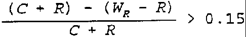
Ensemble constitué d'un câble aérien autoporteur et dispositif à pince de tension comportant un mécanisme de serrage du câble, mécanisme constitué d'au moins une tige enroulée hélicoïdalement autour de la gaine extérieure du câble, où (comme on peut le voir sur la fig. I) C est le diamètre extérieur du câble, R le diamètre de la tige ou de chacune des tiges et W R le diamètre extérieur de l'enroulement non tendu de la tige ou de chacune des tiges.


Abrégé anglais


An assembly comprising a self supporting aerial
cable and tension clamp means including gripping means
for gripping the cable, the gripping means comprising
at least one helically wound rod fitted over the
cable's outer sheath, wherein
(see fig. I) ,
where C is the outer diameter of the cable, R is the
diameter of the or each rod and W R is the outer
diameter of the unstressed winding of the or each rod.

Revendications

Note : Les revendications sont présentées dans la langue officielle dans laquelle elles ont été soumises.


11
CLAIMS:
1. An assembly comprising a self supporting aerial
cable, having an outer sheath, and tension clamp means
including gripping means for gripping the cable, the
gripping means comprising at least one helically wound rod
fitted over the cable's outer sheath, wherein
<IMG>
where C is the outer diameter of the cable, R is the
diameter of the at least one rod and W R is the outer
diameter of the unstressed winding of the at least one
rod.
2. An assembly as claimed in claim 1, wherein
<IMG>
3. An assembly as claimed in claim 2, wherein
<IMG>
is substantially 0.25.

12
4. An assembly as claimed in claim 1, wherein the cable
comprises a tube for receiving optical fibers, the tube
being surrounded by a layer of aramid fibers unimpregnated
with hot melt adhesive.
5. An assembly as claimed in claim 1, wherein the
assembly further comprises dead end means, the dead end
means comprises at least one helically wound rod and is
fitted over a portion of the gripping means, and
<IMG>
where D is the diameter of the at least one rod of the at
least one dead end means and W D is the outer diameter of
the unstressed winding of the at least one rod of the dead
end means.
6. An assembly as claimed in claim 5, wherein
<IMG>
7. An assembly as claimed in claim 6, wherein
<IMG>

13
and
<IMG>
8. An assembly as claimed in claim 5, wherein the dead
end means comprises at least one rod wound in a double
helix and looped over part of a support assembly of said
cable.

Description

Note : Les descriptions sont présentées dans la langue officielle dans laquelle elles ont été soumises.


CA 02240~99 1998-06-12
Aerial Cable and Tension ClamP Assembly
The invention relates to an aerial cab~e and
tension clamp assembly.
Tension clamps are known for supporting all
dielectric self-supporting (ADSS) cables along
overhead routes. Such cables may comprise a glass
reinforced plastics central strength member providing
a relatively rigid and crush resistant cable
structure. More recently developed ADSS cables
comprise a loose tube for containing optical fibres,
the tube being surrounded by a layer of aramid fibres
surrounded by a relatively hard plastics outer sheath.
These fibres may be impregnated with hot melt adhesive
which bonds the fibres together. Alternatively, the
fibres may be more tightly packed and not bonded
together with hot melt adhesive. The latter type of
cable will henceforth be described as an unimpregnated
aramid fibre cable and is particularly suited to use
in hot climates, where operating temperatures may
reach 70~C at the cable core.
One type of known tension clamp comprises an
assembly of reinforcing rods (which typically are
steel rods) each preformed in a helix for fitting over
a particular size and type of cable to produce a
predetermined compressive force for gripping the

CA 02240~99 1998-06-12
~ cable. The amount of compression is conventionally
indicated by
(C + R) - (WR ~ R)
C + R
where C is the outer diameter of the cable, R is the
diameter of each reinforcing rod and WR is the outer
diameter of the winding of the reinforcing rods in an
unstressed (unfitted) condition. The reinforcing rods
compression is commonly less than O.lS (or 15%). The
known tension clamps also comprise a so-called 'dead
end' which is an assembly of rods (again typically
steel rods) fitted over the reinforcing rod assembly
intermediate its ends in a double helix and attached
to a tension point for supporting the cable tension
clamp assembly. The rods of the reinforcing rod
assembly and the dead end may be coated with, for
example, course sand particles for facilitating
frictional engagement therebetween. The compression
exerted by the dead end on the reinforcing rods when
the clamp and cable are not in tension is
conventionally expressed as
(C + 2R + D) - (WO - D)
C + 2R + D
where D is the diameter of each dead end rod, WD is
the outer diameter of the winding of the rods of the
dead end in an unstressed (unfitted) condition and C

CA 02240~99 1998-06-12
- and R are as before. The dead end rods compression is
commonly less than 0.15 (or 15~).
As tension loading is applied to the ca-~le the
dead end tightens up, increasing the compressive force
gripping the reinforcing rods.
Known methods of cable clamp design use the
increasing compressive force of the dead end for
increasing grip on a cable as the tension load
increases. The function of the reinforcing rods is to
transmit the gripping force of the dead end to the
cable and to spread the load along a predetermined
length of cable to prevent excessive localized forces
on the cable. Thus, if a greàter compressive force is
required for increasing grip on the cable, the skilled
man designing a tension clamp assembly for this
purpose would increase the compressive strength of the
dead end, and not that of the reinforcing rods. In
this connection, reinforcing rod assemblies are often
used at suspension only (non-tension) points in an
overhead cable installation, where compressive
strength for firmly gripping the cable for resisting
tensile forces is not required.
A problem has arisen, particularly in connection
with tension clamping of the above-mentioned aramid
fibre containing cable constructions having relatively
hard plastics outer sheaths, whereby increased grip on

CA 02240~99 1998-06-12
the cable is required to mitigate relative movement of
the cable outer sheath and internal elements of the
cable. .~
An object of the present invention is to provide
an aerial cable and tension clamp assembly which
mitigates or prevents the effects of the above-
mentioned problem.
Accordingly, the invention provides an assembly
comprising a self supporting aerial cable and tension
clamp means including gripping means for gripping the
cable, the gripping means comprising at least one
helically wound rod fitted over the cable's outer
sheath, wherein
(C + R) - (WR - R) > O 15
where C is the outer diameter of the cable, R is the
diameter of the or each rod and WR is the outer
diameter of the unstressed winding of the or each rod.
Preferably,
(C + R) - (WR ~ R) ~ O 2
C + R
Preferably,
(C + R) - (WR - R)
C + R
is substantially 0.25.
The cable may comprise a tube for receiving

CA 02240~99 1998-06-12
optical fibres, the tube being surrounded by a layer
of aramid fibres unimpregnated with hot melt adhesive.
Preferably, the assembly further compris~s-dead
end means, the dead end means comprises at least one
5helically wound rod and is fitted over a portion of
the gripping means, and
(C + R) - (WR ~ R) 1 5 (C + 2R + D) - (WD ~ D)
C + R C + 2R + D
where D is the diameter of the or each rod of the dead
end means and WD is the outer diameter of the
unstressed winding of the or each rod of the dead end
10means.
Preferably,
(C + R) - (WR ~ R) 2 2 (C + 2R + D) - (WD ~ D)
C + R C + 2R + D
Preferably,
(C + R) ~ (WR ~ R) = 0.25
C + R
and (C + 2R + D) - (WD ~ D) 0 075
C + 2R + D
The dead end means may comprise at least one said
rod wound in a double helix and looped over part of a
support assembly.
In order that the invention may be better
understood, an embodiment thereof, which is given by

CA 02240~99 1998-06-12
way of example only, will now be described with
reference to the accompanying drawings, in which:
Figure 1 shows an assembly comprising a ca~le and
tension clamp means fitted to the cable; and
Figure 2 is a graph relating to the results of
tensile tests for long span cables and showing the
maximum tension load in cables supported by various
tension clamp systems against variations in operating
temperature.
Referring to Figure 1, the illustrated assembly
1 comprises an ADSS cable 2 of the type comprising a
loose tube surrounded by unimpregnated aramid fibres,
gripping means 4 comprising an assembly of steel rods
preformed in a helix and fitted over the cable 2 for
gripping the cable 2, and dead end means 6 comprising
an assembly of steel rods wound in a double helix and
fitted over the gripping means 4 intermediate the ends
thereof for supporting the gripping means 4. The dead
end means 6 is looped over a U-shaped runner 8
attached to a shackle lo connected to a tension point
of an overhead cable support structure. The portion
of the dead end means 6 which is fitted over the
gripping means 4 is shorter axially than the gripping
means 4.
In the assembly 1 shown in Figure 1, the cable
outer sheath has an outer diameter C when not subject

CA 02240~99 1998-06-12
to compressive stresses and the rod assembly of the
gripping means 4 has a winding outer diameter WR when
in the unstressed condition and a rod diameter-~. The
gripping means 4 grips the cable 1 with a compressive
force approximately dependent on the compression,
(C + R) - (WR - R)
C + R
The compression of the gripping means 4 is 0.25 (or
25%). The rod assembly of the dead end means 6 has a
winding outer diameter WD in the unstressed condition
thereof and a rod diameter D. The dead end means 6
exerts a compressive force on the gripping means 4
approximately dependent on the compression,
(C + 2R + D) - (WD - D)
C + 2R + D
The compression of the gripping means 4 is 0.075 (or
7.5%). The dead end means 6 has primarily a
supporting function in that it connects the gripping
means 4 to the runner 8 at the tension point, whilst
the gripping means 4 provides an increased (in
comparison with known cable tension clamp assemblies)
gripping force which is strong enough to hold the
relatively hard cable outer sheath and compress the
aramid fibres to prevent substantial relative movement
between the outer sheath and the internal elements of
the cable 1.

'~ CA 02240~99 1998-06-12
This assembly 1 provides greatly improved
performance over conventional assemblies wherein, as
described above, the compression of the dead-,Jend is
conventionally increased if increased grip on the
cable is required, in accordance with conventional
design rules.
Figure 2 shows the performance (maximum load
held) of an assembly, shown by line C, in tests for a
range of operating temperatures. This assembly is
similar to the assembly 1 but has a gripping means
compression of 0.25 (or 25%) and a dead end
compression of 0.15 (or 15%). Lines A, B and D show
the comparable results of tests carried out on
assemblies having 0.15 (15%) reinforcing rod
compression but dead end compressions of 0.20 (20%),
0.15 (15%) and 0.09 (9%) respectively. The maximum
load held is also shown in terms of multiples of the
maximum working tension (MWT) the cable is likely to
experience when subjected to environmental conditions
such as ice and wind loading. The cables used in
these tests were of the unimpregnated aramid fibre
type.
These results are surprisingly good for the
assembly of line C in view of the previous bias in the
art towards increasing the dead end compression to
increase grip on the cable and against adjusting the

CA 02240~99 1998-06-12
reinforcing rod compression. In particular, it can be
seen that a maximum load of 3 x MWT can be maintained
even in the temperature range 50~C to 70~C. ,~ -
The assembly 1 is advantageous also in that
widely available components can be used in its
construction to obtain the increased performance.
Whilst the assembly 1 can be used with particular
advantage for supporting ADSS cables having
unimpregnated aramid fibre construction, it can also
be used for supporting other types of cable.
To maximise the effects of the invention it is
preferable that gripping means 4 has a compression of
at least 1.5 times the compression of the dead end
means 6, that is to say
(C + R) - (WR ~ R) 1 5 (C + 2R + D) - ~WD ~ D)
C + R C + 2R + D
15More preferably,
(C + R) - (WR ~ R) 2 2(C + 2R + D) - (WD ~ D)
C + R C + 2R + D
In the embodiment described above, the gripping
means compression is four times that of the dead end
means. This, of course, is contrary to the accepted
design rules, whereby the compression of the dead end
means should be equal to the compression of the

CA 02240599 1998-06-12
reinforcing rods (cf the 0.15:0.15 compression
relationship mentioned earlier in relation to known
tension clamps) or the compression of the dqad end
means should be increased in relation to the
- 5 compression of the reinforcing rods.

Dessin représentatif
Une figure unique qui représente un dessin illustrant l'invention.
États administratifs

2024-08-01 : Dans le cadre de la transition vers les Brevets de nouvelle génération (BNG), la base de données sur les brevets canadiens (BDBC) contient désormais un Historique d'événement plus détaillé, qui reproduit le Journal des événements de notre nouvelle solution interne.

Veuillez noter que les événements débutant par « Inactive : » se réfèrent à des événements qui ne sont plus utilisés dans notre nouvelle solution interne.

Pour une meilleure compréhension de l'état de la demande ou brevet qui figure sur cette page, la rubrique Mise en garde , et les descriptions de Brevet , Historique d'événement , Taxes périodiques et Historique des paiements devraient être consultées.

Historique d'événement

Description Date
Le délai pour l'annulation est expiré 2009-06-12
Lettre envoyée 2008-06-12
Lettre envoyée 2007-05-16
Inactive : CIB de MCD 2006-03-12
Accordé par délivrance 2003-12-09
Inactive : Page couverture publiée 2003-12-08
Préoctroi 2003-09-18
Inactive : Taxe finale reçue 2003-09-18
Un avis d'acceptation est envoyé 2003-03-21
Lettre envoyée 2003-03-21
Un avis d'acceptation est envoyé 2003-03-21
Inactive : Approuvée aux fins d'acceptation (AFA) 2003-02-27
Lettre envoyée 2001-02-23
Exigences pour une requête d'examen - jugée conforme 2001-02-09
Toutes les exigences pour l'examen - jugée conforme 2001-02-09
Modification reçue - modification volontaire 2001-02-09
Requête d'examen reçue 2001-02-09
Demande publiée (accessible au public) 1998-12-13
Inactive : CIB en 1re position 1998-09-16
Symbole de classement modifié 1998-09-16
Inactive : CIB attribuée 1998-09-16
Inactive : Transfert individuel 1998-09-10
Modification reçue - modification volontaire 1998-09-10
Inactive : Lettre de courtoisie - Preuve 1998-09-01
Inactive : Certificat de dépôt - Sans RE (Anglais) 1998-08-27
Demande reçue - nationale ordinaire 1998-08-24

Historique d'abandonnement

Il n'y a pas d'historique d'abandonnement

Taxes périodiques

Le dernier paiement a été reçu le 2003-05-27

Avis : Si le paiement en totalité n'a pas été reçu au plus tard à la date indiquée, une taxe supplémentaire peut être imposée, soit une des taxes suivantes :

  • taxe de rétablissement ;
  • taxe pour paiement en souffrance ; ou
  • taxe additionnelle pour le renversement d'une péremption réputée.

Les taxes sur les brevets sont ajustées au 1er janvier de chaque année. Les montants ci-dessus sont les montants actuels s'ils sont reçus au plus tard le 31 décembre de l'année en cours.
Veuillez vous référer à la page web des taxes sur les brevets de l'OPIC pour voir tous les montants actuels des taxes.

Historique des taxes

Type de taxes Anniversaire Échéance Date payée
Enregistrement d'un document 1998-06-12
Taxe pour le dépôt - générale 1998-06-12
TM (demande, 2e anniv.) - générale 02 2000-06-12 2000-05-18
Requête d'examen - générale 2001-02-09
TM (demande, 3e anniv.) - générale 03 2001-06-12 2001-05-22
TM (demande, 4e anniv.) - générale 04 2002-06-12 2002-05-22
TM (demande, 5e anniv.) - générale 05 2003-06-12 2003-05-27
Taxe finale - générale 2003-09-18
TM (brevet, 6e anniv.) - générale 2004-06-14 2004-05-25
TM (brevet, 7e anniv.) - générale 2005-06-13 2005-05-20
TM (brevet, 8e anniv.) - générale 2006-06-12 2006-05-17
Enregistrement d'un document 2007-04-19
TM (brevet, 9e anniv.) - générale 2007-06-12 2007-05-17
Titulaires au dossier

Les titulaires actuels et antérieures au dossier sont affichés en ordre alphabétique.

Titulaires actuels au dossier
PRYSMIAN CABLES & SYSTEMS LIMITED
Titulaires antérieures au dossier
MARTIN VINCENT DAVIES
RALPH SUTEHALL
SAM ARMITAGE
Les propriétaires antérieurs qui ne figurent pas dans la liste des « Propriétaires au dossier » apparaîtront dans d'autres documents au dossier.
Documents

Pour visionner les fichiers sélectionnés, entrer le code reCAPTCHA :


Pour visualiser une image, cliquer sur un lien dans la colonne description du document. Pour télécharger l'image (les images), cliquer l'une ou plusieurs cases à cocher dans la première colonne et ensuite cliquer sur le bouton "Télécharger sélection en format PDF (archive Zip)" ou le bouton "Télécharger sélection (en un fichier PDF fusionné)".

Liste des documents de brevet publiés et non publiés sur la BDBC .

Si vous avez des difficultés à accéder au contenu, veuillez communiquer avec le Centre de services à la clientèle au 1-866-997-1936, ou envoyer un courriel au Centre de service à la clientèle de l'OPIC.


Description du
Document 
Date
(aaaa-mm-jj) 
Nombre de pages   Taille de l'image (Ko) 
Dessin représentatif 1998-12-22 1 1
Dessin représentatif 2003-11-04 1 2
Revendications 2001-02-08 3 48
Abrégé 1998-06-11 1 12
Description 1998-06-11 10 274
Revendications 1998-06-11 2 43
Dessins 1998-06-11 2 21
Dessins 1998-09-09 2 20
Certificat de dépôt (anglais) 1998-08-26 1 174
Courtoisie - Certificat d'enregistrement (document(s) connexe(s)) 1998-10-25 1 114
Rappel de taxe de maintien due 2000-02-14 1 113
Accusé de réception de la requête d'examen 2001-02-22 1 179
Avis du commissaire - Demande jugée acceptable 2003-03-20 1 160
Avis concernant la taxe de maintien 2008-07-23 1 171
Correspondance 1998-08-31 1 28
Correspondance 2003-09-17 1 32