Sélection de la langue

Search

Sommaire du brevet 2241191 

Énoncé de désistement de responsabilité concernant l'information provenant de tiers

Une partie des informations de ce site Web a été fournie par des sources externes. Le gouvernement du Canada n'assume aucune responsabilité concernant la précision, l'actualité ou la fiabilité des informations fournies par les sources externes. Les utilisateurs qui désirent employer cette information devraient consulter directement la source des informations. Le contenu fourni par les sources externes n'est pas assujetti aux exigences sur les langues officielles, la protection des renseignements personnels et l'accessibilité.

Disponibilité de l'Abrégé et des Revendications

L'apparition de différences dans le texte et l'image des Revendications et de l'Abrégé dépend du moment auquel le document est publié. Les textes des Revendications et de l'Abrégé sont affichés :

  • lorsque la demande peut être examinée par le public;
  • lorsque le brevet est émis (délivrance).
(12) Demande de brevet: (11) CA 2241191
(54) Titre français: TIROIR DE REMPLACEMENT DE PLAQUES POUR CUVE METALLURGIQUE ET ENSEMBLE DE PLAQUES POUR CE TIROIR
(54) Titre anglais: PLATE CHANGE DRAWER FOR A METALLURGICAL VESSEL AND SET OF PLATES FOR THIS DRAWER
Statut: Réputée abandonnée et au-delà du délai pour le rétablissement - en attente de la réponse à l’avis de communication rejetée
Données bibliographiques
(51) Classification internationale des brevets (CIB):
  • B22D 41/38 (2006.01)
  • B22D 41/24 (2006.01)
  • B22D 41/28 (2006.01)
  • B22D 41/34 (2006.01)
  • B22D 41/56 (2006.01)
(72) Inventeurs :
  • RICHARD, FRANCOIS-NOEL (France)
(73) Titulaires :
  • VESUVIUS FRANCE S.A.
  • VESUVIUS FRANCE S.A.
(71) Demandeurs :
  • VESUVIUS FRANCE S.A. (France)
  • VESUVIUS FRANCE S.A. (France)
(74) Agent: SMART & BIGGAR LP
(74) Co-agent:
(45) Délivré:
(86) Date de dépôt PCT: 1996-12-18
(87) Mise à la disponibilité du public: 1997-07-10
Requête d'examen: 2001-10-29
Licence disponible: S.O.
Cédé au domaine public: S.O.
(25) Langue des documents déposés: Anglais

Traité de coopération en matière de brevets (PCT): Oui
(86) Numéro de la demande PCT: PCT/EP1996/005685
(87) Numéro de publication internationale PCT: WO 1997024201
(85) Entrée nationale: 1998-06-23

(30) Données de priorité de la demande:
Numéro de la demande Pays / territoire Date
95/15885 (France) 1995-12-26

Abrégés

Abrégé français

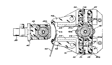
Tiroir de remplacement de plaques conçu pour une cuve métallurgique, telle qu'un distributeur de coulée continue (2). Ce tiroir possède un châssis (12) monté sous la cuve métallurgique, au moins une plaque supérieure fixe (18) et au moins une plaque inférieure remplaçable (22), des moyens destinés à exercer une pression afin de pousser la plaque inférieure (22) contre la plaque fixe, le châssis (12) possédant des moyens de guidage destinés à recevoir une plaque inférieure de remplacement (22) le long du côté de la plaque inférieure (22) pendant la coulée, ainsi que des moyens d'actionnement destinés à amener la plaque inférieure de remplacement (22) à la place de la plaque pendant la coulée. La plaque supérieure fixe (18) et la plaque inférieure remplaçable (22) possèdent des périphéries polygonales identiques et sont décalées angulairement, de manière à ne pas se chevaucher complètement. La périphérie polygonale de la plaque est un carré ou un carré pourvu de coins arrondis.


Abrégé anglais


Plate change drawer for a metallurgical vessel such as a continuous casting
distributor (2). The drawer has a chassis (12) mounted under the metallurgical
vessel, at least one fixed upper plate (18) and at least one replaceable lower
plate (22), means of applying pressure to force the lower plate (22) against
the fixed plate, the chassis (12) having guide means for receiving a lower
replacement plate (22) alongside the lower plate (22) during pouring, and
actuation means for bringing the lower replacement plate (22) in place of the
plate during pouring. The upper fixed plate (18) and the lower replaceable
plate (22) have identical polygonal peripheries and are offset angularly so
that they do not overlap completely. The polygonal periphery of the plate is a
square or a square with rounded corners.

Revendications

Note : Les revendications sont présentées dans la langue officielle dans laquelle elles ont été soumises.


CLAIMS
1. Plate change drawer for a metallurgical vessel such as a continuous casting
distributor (2), the drawer having a chassis (12) mounted under the metallurgical
vessel, at least one fixed upper plate (18) and at least one replaceable lower
plate (22) said upper plate (18) and said lower plate (22) having a taphole (21).
means for applying pressure to force the lower plate (22) against the fixed plate,
the chassis (12) having guide means for receiving a lower replacement plate
(22a) a longside the lower plate (22) during pouring, and actuation means for
bringing the lower replacement plate (22a) in the place of the plate during
pouring (22), characterized in that the upper fixed plate (18) and the lower
replaceable plate (22) have identical polygonal peripheries and are offset
angularly so that they do not overlap completely.
2. Drawer according to claim 1, characterized in that the polygonal periphery of the plates is a square or a square with rounded corners.
3. Drawer according to claim 2, characterized in that the taphole (21) is placed in
the center of the square for each plate.
4. Drawer according to claim 2 or 3, characterized in that the fixed plate (18) and
the replaceable plate (22) are offset angularly by 45° so that two zones (18b) of
the fixed upper plate (18) lateral to the direction of introduction of the lowerreplaceable plates (22, 22a) are never covered by these lower plates (22, 22a).
5. Drawer according to claim 4, characterized in that the two zones (18b) of thefixed plates (18) lateral to the direction of introduction of the plates that are
never covered by the lower plates (22) are used to fasten it on the chassis (12)of the drawer.

6. Drawer according to claim 5, characterized in that it has two screws (30) with
a conical end (30a), each of which acts on an edge of the fixed plate located inthe lateral zone (18b) not covered by the lower plate (22), these edges being
located in front of this fixed plate with respect to the direction of introduction
of the replacement plates in order to push the fixed plate toward the back and
against the chassis (12) of the drawer.
7. Set of two plates for a plate change drawer for a metallurgical vessel comprised
of an upper plate (18) and of a lower plate (22), each of said plates (18,22)
having a working surface, said working surfaces being designed for sliding one
on the other, the plates also having a taphole (21), characterised in that theseplates (18,22) have identical square peripheries, and in that the taphole (21) is
situated in the center of the periphery.
8. Set of two plates according to claim 7, characterized in that the periphery of the
fixed plate has elastic means placed on two sides adjacent to a corner of the
square periphery for automatic positioning of the two opposite sides of the
square against rigid supports effected in the chassis (12) for receiving them,
during the mounting of the fixed plate.
9. Set of two plates according to claim 7 or 8, characterized in that they are
provided with identical metal envelopes.
10. Set of two plates according to any of claims 7 to 9, characterised in that the
plates (18,22) have rounded angles.

Description

Note : Les descriptions sont présentées dans la langue officielle dans laquelle elles ont été soumises.


CA 02241191 1998-06-23
W O97/24201 PCTAEP96105685
PLAT~ C~ANGE DRAWER FOR A METALLURGICAL VE~SEL
AND SET OF PLATES FOI~ THlS DRAWER
The invention concerns a plate change drawer for a metallurgical vessel such as a
continuous casting distributor; the drawer has a chassis mounted under the
metallurgical vessel, at least one fixed upper plate and at least one replaceable lower
plate, prt;~ule means for applying the lower plate against the f~ed plate, the chassis
having means of guidance for receiving a lower replacement plate alongside the lower
plate during casting and actuation means for bringing the lower replacement plate in the
place of the plate during casting.
Technological background
In the continuous casting of steel the metal is tranfered into successive vessels such as
ladles and disL ibulol~. One or more pouring holes are provided in the bottom of each
container for casting the metal.
The flow can be regulated by different means such as plate closures, stopper rods or
simply a calibrated nozzle.
Some applications call for protection of the molten metal from the surrounding air. A
refractory jet protection tube is then f~ten~d under the vessel to surround the jet as it
emerges from the pouring hole.
Whatever the type of pouring refractory used, these refractories wear out and have to
be changed so that the casting can be continued with the same vessel.
Various solutions are already known for exch~nging refractories without interrupting
the pouring. For example, Belgian Patent N~ 214,385 describes a tube ch~nging device.
In a device of this type the taphole is terminated by a fixed plate. A lower plate
combined with a jet ~lote~;Lion tube is laid against the fixed plate to assure a tight joint.
7 i -~ 3 CONFlRMATlt)N COPY

D CA 02241191 1998-06-23
When this plate and the jet protection tube associated with it have to be replaced, the
plate of a new plate/tube assembly is placed alongside the plate to be changed and
pushed by adequate means. The new plate expels the worn plate and takes its place.
To assure a perfect alignment of the upper tace of the lower plate with the lower tace
of the upper plate, the fixed upper plate is generally longer than the lower plate at least
on the side of introduction of the replacement plate so that the new plate can be
introduced against the end of the upper plate when the plate to be replaced is still in the
pouring position.
These plates are frequently surrounded with a metal envelope. The use of a metalenvelope makes it possible to obtain a plate ready tor use, the outside dimensions ot
which are well-defined and which has resistant integrated sliding and support surtaces.
The metal envelope also permits m~inr~inino. the cohesion of the refractory material
when cracks appear under the effect of thermal and mechanically elevated stresses
induced by the casting conditions.
E;xposition of the technical problem
Because the upper plate is longer, it is also more costly to produce.
On the other hand, the fact that the dimensions of the plates are different necessitates
the management of different components, particularly when the refractory plates are
surrounded by a metal envelope, the production of which requires a costly investment
in tooling equipment. The purpose of the present invention is a plate changing drawer
that resolves these disadvantages.
According to the invention, the upper plate and the lower plate have identical polygonal
peripheries and are angularly offset so that they do not overlap completely.
Thus, the surface of the fixed plate directed toward the replacement plate that is not
covered by the plate during pouring can serve as a guide surface for the replacement
VESUVIUS ~ANCE SA - Dockc~ 1118 - Cas 78 - Rcv~s~d Novcr~bcr 19, 1997
p~ ,g S~
.

CA 02241191 1998-06-23
W O97/24201 PCT~EP96/05685
plate. Thus, although the surfaces of the plates are equal, we have a guide surface that
permits a perfect ~lignment of the upper face of the lower plate with the lower surface
of the upper plate.
Furthermore, the same metal envelope can be used for the two types of plates, also in
the case where their internal co~ n is different. The cost of the tooling equipment
n~o~e.c~ry for producing the metal envelopes is cut in two.
Preferably, the polygonal periphery of the plates is a square and a taphole is placed in
the center of the square.
Also preferably, the fixed plate and the replaceable plate are offset angularly by 45~.
Preferably, the two surfaces lateral to the direction of introduction of the plates of the
fixed plate which are never covered by the lower plate, either when the plates are in
the casting position or during the ch~nging of plates, are used to fix it on the drawer
chassis, for example, by means of screws with a conical end, each acting on one edge
of the fixed plate sit~l~t~ in the lateral zone not covered by the lower plate, these edges
being situated at the front of this fixed plate with respect to the direction of introduction
of the replacement plates in order to move the fixed plate simultaneously towards the
back and against the drawer chassis.
One is then sure that during the successive plate changes the f~ed plate would not be
displaced to recover a possible assembling play, which would then run the risk of
damaging the joint of the fixed plate with the casting spout inside of the distributor.
Other characteristics and advantages of the present invention will become evident in
reading the following description with reference to the attached figures.
Figure 1 is a longitudinal cross sectional view of a plate ch~n~ing drawer in accordance
with the invention.
Figure 2 is a bottom view of the plate ch~nging drawer shown in Figure 1.
On figure 1 a di~llilJuLor 2 has a bottom wall of steel 4 covered with a protective layer

CA 02241191 1998-06-23
W O 97/24201 PCTAEr~61'~5~8
of refractory material 6. A pouring orifice or taphole 8 is effected in the bottom of the
distributor 2. A plate ch~nging drawer design~tçd as a whole by the general reference
10 is mounted under the distributor 2. A ring 14 is welded inside of the distributor on
the bottom wall. Screws 16 fasten the chassis 12 of the drawer on this ring 14. A fixed
S refractory plate 18 is placed in a seat 20 of the chassis 12. A lower plate 22 is located
under the fixed plate 18. The plate 22 is applied against the fixed plate 18 by means of
ples~ul~ application con~ ,d in the example shown by four rocker arms 24. As canbe seen of Figure 2, each rocker arm has one end applied on the lower face of the
lower plate 22, and one end 24b pressed downward by a helicoidal spring 26.
F,~senti~lly at its central part the rocker arm 24 is artic~ t~ on a bolt with a spherical
head 28. The action exerted on the lower plate by these means of pressure application
makes it possible to effect a tight iunction of the fixed plate 18 and the lower plate 22.
As can be seen on Figure 2, the fixed plate 18 and the lower plate 22 have identical
peripheries, i.e, of the same shape and the same surface.
The fact that the plates 18 and 22 have identical peripheries is advantageous because
this permits use of the same metal envelopes for these two plates. In this manner a
single tooling outfit is sufficient. The investment required is thus cut in two.
The plates are preferably square. For practical reasons, notably of m~nllf~tllre, the
angles of the squares are rounded. The fixed plate 18 and the lower plate 22 have a
taphole 21. This taphole is placed in the center of the square periphery.
It is also noted that the fixed plate 18 and the lower plate 22 are angularly offset. In this
manner, their surfaces are not covered completely. More particularly, the surface of the
fixed plate 18 is not covered completely by the lower plate 22.,
At the front of the fixed plate 18 with respect to the direction of introduction and
exch~nge of the plates there is a triangular zone (the vertex of which is rounded) 18a.
Apart from a plate ex~,h~nge, this zone is not covered by the lower plate 22. It can thus

J CA 02241191 1998-06-23
be used as a guide surtace for the replacement plate. Thus, although the surfaces of the
plates are equal, there is a guide sur~Face that permits a pert'ect alignment of the upper
face of the lower plate with the lower t'ace of the upper plate.
S On either side of the plate 18, laterally with respect to the direction of plate change,
there are two zones 18b, triangular in shape with a rounded end. These two zones are
never covered by the lower plate 12, even during a plate exchange. These zones 18b
can thus be used to maintain the fixed plate 18 towards the bottom of the seat 20 and
towards the back of the frame 22. For this, the fixed plate is held in its seat '0 by two
screws 30 that have a conical head 30a. The conical end 30a of each of the two screws
30 acts on an edge of the fixed plate 18 located in zone 18b, at the front of this zone
with respect to the direction of introduction of the plates. The conical ends exert an
action that applies the plate 18 toward the bottom of the seat '0. i.e., upward. and
simultaneously an action that applies the fixed plate 18 towards the back of the frame
12 with respect to the direction of introduction of the plates.
It is advantageous to apply the fixed plate 18 toward the back of the frame to avoid a
backlash between the plate 18 and the back corner of the seat 20 when the plates are
exchanged. In effect, this backlash, even minim~l, would have the effect of impairing
the quality of the joint between the fixed plate 18 and the mass to be rammed 3'' located
in the thickness of the refractory lining 6 of the distributor 2. The screws 30 make it
possible to eliminate this play.
According to an actualization variant, the periphery of the fixed plate 18 has elastic
means placed on two sides adjacent to an angle of the square periphery. These elastic
means, comprised for example on elastic fibers or cardboard, are located at the time
of assembly of the plate 18 in its seat 20 toward the front of the frame so as to
automatically position to the two opposite sides of the square against rigid supports
effected in the chassis 12 for receiving them.
The chassis 12 has a guide means that permit receiving a lower replacement plate 2''a
along side the lower plate 22 during casting. In the exemplary embodiment shown the
VESUVrUS FRA~CE SA - Dockc~ 1118 - Cas 78 - Rcvisc~l ~ovcmbcr 19, 1997 ~,
~ o

CA 02241191 1998-06-23
W O 97/24201 PCTAEP96/05685
guide means are comprised of a slide rail 34 (see Figure 2) located toward the front of
the m~rhinP with respect to the direction of introduction of the rep}acement plate 22a.
The plate 22a is mounted on a support 36. Actuation means comprised, for example,
of a hydraulic or pneumatic jack 38 are con~ d to the support 36.
s
First, the lower replacement plate 22a is introduced into the slide rails 34 until the
crosspiece 40 that is part of tne means of support is retained behind two arms 42
artir~ tp~ on the chassis 12. The two arms 42 are connP-cte~l by an el~tic means 44.
When the support 36 carrying the repl~ment plate 22a is introduced, the artic~ tlod
arms pivot around tneir axis so that tneir ends are separated. When the support 36 is
introduced sufficiently into the guide means 34, the ends of the arti( ~ tP~l arms 42 will
lock on the crosspiece 40. At this time the replacement plate 22a is essentially in
contact with the lower plate 22 in tne pouring position. The ~tll~til~n means 38 are then
set in motion to expel the plate during pouring to replace it with the new plate 22a. The
position shown in Figure 1 is then occupied. The worn lower plate falls 'oy itself out
of the guide means.
~; The operator then acts on a lever arm 46 that deflects the two artirlll~t~cl arms 42 to
free the support 36 and the crosspiece 40 and equip it with a new replacement plate.~0

Dessin représentatif
Une figure unique qui représente un dessin illustrant l'invention.
États administratifs

2024-08-01 : Dans le cadre de la transition vers les Brevets de nouvelle génération (BNG), la base de données sur les brevets canadiens (BDBC) contient désormais un Historique d'événement plus détaillé, qui reproduit le Journal des événements de notre nouvelle solution interne.

Veuillez noter que les événements débutant par « Inactive : » se réfèrent à des événements qui ne sont plus utilisés dans notre nouvelle solution interne.

Pour une meilleure compréhension de l'état de la demande ou brevet qui figure sur cette page, la rubrique Mise en garde , et les descriptions de Brevet , Historique d'événement , Taxes périodiques et Historique des paiements devraient être consultées.

Historique d'événement

Description Date
Inactive : CIB de MCD 2006-03-12
Le délai pour l'annulation est expiré 2003-12-18
Demande non rétablie avant l'échéance 2003-12-18
Réputée abandonnée - omission de répondre à un avis sur les taxes pour le maintien en état 2002-12-18
Lettre envoyée 2001-11-22
Requête d'examen reçue 2001-10-29
Exigences pour une requête d'examen - jugée conforme 2001-10-29
Toutes les exigences pour l'examen - jugée conforme 2001-10-29
Inactive : CIB attribuée 1998-10-02
Inactive : CIB en 1re position 1998-10-02
Inactive : CIB attribuée 1998-10-02
Symbole de classement modifié 1998-09-29
Inactive : Lettre de courtoisie - Preuve 1998-09-15
Inactive : Notice - Entrée phase nat. - Pas de RE 1998-09-11
Inactive : Demandeur supprimé 1998-09-11
Inactive : Correspondance - Formalités 1998-09-01
Inactive : Transfert individuel 1998-09-01
Demande reçue - PCT 1998-08-28
Demande publiée (accessible au public) 1997-07-10

Historique d'abandonnement

Date d'abandonnement Raison Date de rétablissement
2002-12-18

Taxes périodiques

Le dernier paiement a été reçu le 2001-12-07

Avis : Si le paiement en totalité n'a pas été reçu au plus tard à la date indiquée, une taxe supplémentaire peut être imposée, soit une des taxes suivantes :

  • taxe de rétablissement ;
  • taxe pour paiement en souffrance ; ou
  • taxe additionnelle pour le renversement d'une péremption réputée.

Veuillez vous référer à la page web des taxes sur les brevets de l'OPIC pour voir tous les montants actuels des taxes.

Historique des taxes

Type de taxes Anniversaire Échéance Date payée
Taxe nationale de base - générale 1998-06-23
Enregistrement d'un document 1998-09-01
TM (demande, 2e anniv.) - générale 02 1998-12-18 1998-12-03
TM (demande, 3e anniv.) - générale 03 1999-12-20 1999-12-07
TM (demande, 4e anniv.) - générale 04 2000-12-18 2000-12-01
Requête d'examen - générale 2001-10-29
TM (demande, 5e anniv.) - générale 05 2001-12-18 2001-12-07
Titulaires au dossier

Les titulaires actuels et antérieures au dossier sont affichés en ordre alphabétique.

Titulaires actuels au dossier
VESUVIUS FRANCE S.A.
Titulaires antérieures au dossier
FRANCOIS-NOEL RICHARD
Les propriétaires antérieurs qui ne figurent pas dans la liste des « Propriétaires au dossier » apparaîtront dans d'autres documents au dossier.
Documents

Pour visionner les fichiers sélectionnés, entrer le code reCAPTCHA :


Pour visualiser une image, cliquer sur un lien dans la colonne description du document. Pour télécharger l'image (les images), cliquer l'une ou plusieurs cases à cocher dans la première colonne et ensuite cliquer sur le bouton "Télécharger sélection en format PDF (archive Zip)" ou le bouton "Télécharger sélection (en un fichier PDF fusionné)".

Liste des documents de brevet publiés et non publiés sur la BDBC .

Si vous avez des difficultés à accéder au contenu, veuillez communiquer avec le Centre de services à la clientèle au 1-866-997-1936, ou envoyer un courriel au Centre de service à la clientèle de l'OPIC.


Description du
Document 
Date
(aaaa-mm-jj) 
Nombre de pages   Taille de l'image (Ko) 
Dessin représentatif 1998-10-06 1 21
Description 1998-06-23 6 273
Dessins 1998-06-23 2 72
Abrégé 1998-06-23 1 65
Revendications 1998-06-23 2 73
Page couverture 1998-10-06 2 77
Rappel de taxe de maintien due 1998-09-10 1 115
Avis d'entree dans la phase nationale 1998-09-11 1 209
Courtoisie - Certificat d'enregistrement (document(s) connexe(s)) 1998-11-03 1 114
Rappel - requête d'examen 2001-08-21 1 129
Accusé de réception de la requête d'examen 2001-11-22 1 179
Courtoisie - Lettre d'abandon (taxe de maintien en état) 2003-01-15 1 176
PCT 1998-06-23 12 411
Correspondance 1998-09-15 1 30
Correspondance 1998-09-01 2 108
Taxes 1999-12-07 1 44
Taxes 2000-12-01 1 46
Taxes 1998-12-03 1 48
Taxes 2001-12-07 1 41