Note : Les descriptions sont présentées dans la langue officielle dans laquelle elles ont été soumises.
CA 02242662 1998-07-10
1
PATENT APPLICATION
TITLE:
MACHINE DIRECTION PROFILING OF EXTENDED NIP PRESS SHOE
The present invention relates to papermaking machines in general
and to extended nip presses in particulars.
Paper is made from a stock contained over 99 percent water and
less that 1 percent fiber by weight. The stock is formed into a web which
has a water content of less than 5 percent by weight. The paper making
process consists of forming a web from the dilute stock suspension of
fibers in water by removing the water from the web. The removal of water
from the formed web must typically be accomplished in a way which
maximizes web strength, maximizes web thickness and minimizes cost.
Water is removed through three principal mechanisms: draining,
pressing, and drying. Typically the draining process is the least costly. In
draining, the fiber content of the web is taken from the stock fiber content
of less than one percent to between about 1 O and 15 percent. Next the
fiber content is increased to between 30 and 35 percent fiber by pressing
water from the web. The remainder of the water which must be removed
to increase the web fiber content to 95 percent fiber is accomplished by
drying the web.
Drying is typically accomplished by wrapping the web about steam
heated dryer rolls and evaporating the water from the web. Drying is an
expensive process because of the heat energy which must be supplied to
evaporate water from the web. Because the drying process is relatively
slow, the number and size of dryers required to remove the water
CA 02242662 1998-07-10
2
remaining after pressing contributes to a considerable fraction of the overall
cost of a papermaking machine. Furthermore, the dryers take up a majority
of the volume occupied by the papermaking machine.
To improve the performance of papermaking machines and to
facilitate operating at higher speed, the extended nip press was developed.
Pressing a paper web typically involves passing the web supported
between two press fabrics through a nip formed between two rolls. The
pressure developed in the nip presses water from the web into the
supporting press fabrics. The nip between two rolls has a width in the
machine direction of less than one inch. The width of a nip between two
rolls can be increased to a limited extent by making one or both of the rolls
compliant. On the other hand an extended nip press employs a shoe which
has a concave contact surface which engages the backing roll to form a nip
having a width of 8 to 12 inches in the machine direction.
The extended nip press shoe is placed within a looped blanket which
slides over the concave surface of the shoe on a film of oil. A paper web
supported between pressing felts is passed between the backing roll and
the blanket supported by the shoe. The shoe is mounted on a bearing pin
to a hydraulic actuator which urges the shoe against the backing roll. The
greater width of the nip in an extended nip press allows more time for
water to move from the web into the press felt. By removing more water
in the pressing section the web fiber content can be increased to forty to
forty-five percent or more. This reduces the number of dryers required in
the dryer section and the amount of energy required to dry the web. This
results in a considerable increase in overall economic efficiency in a
papermaking machine.
In an extended nip press, where the shoe is supported on a single
pin, the pressure on the web as it moves through the extended nip is
CA 02242662 1998-07-10
3
controlled by the shape of the shoe and the position of the pin beneath the
shoe.
One problem with an extended nip press is that as the pressure in
the nip decreases as the web leaves the nip, water can move from the
press fabric back into the web, rewetting it. To overcome this problem,
the pressure profile of the nip in the machine direction is tailored to
increase the pressure towards the trailing or exit side of the nip. This
increased pressure can overcome or decrease rewetting.
Various ways of achieving a pressure profile of a certain
characteristic have been developed. The placement of the support pin and
the shape of the shoe can control the pressure profile. Other techniques
employ two hydraulic support actuators under the shoe. These techniques
involve moving the center of support beneath the shoe. It is often desirable
to be able to adjust the loading between the shoe and the backing roll as
well as the shape of the pressure profile while the machine is running.
Various furnishes used to form a paper web may require varying the total
nip pressure and nip pressure profile.
Controlling paper quality over time may also require adjusting the
total nip pressure as well as the shape of the nip pressure profile. Current
techniques for performing this operation result in the center of support
moving when the shape of the nip pressure profile is varied. Varying the
center of support can limit the ability to independently control the two
variables of nip pressure profile shape and nip total load.
What is needed is an extended nip press where the shoe support
system can vary the nip loading and the shape of the pressure profile
independently.
CA 02242662 1998-07-10
4
The extended nip press of this invention has a shoe which is
supported on a central hydraulic actuator. The actuator has a piston which
engages the shoe along a load support line formed by a pin. The piston
urges the shoe against a backing roll. A pair of hydraulic actuators applies
a pure couple about the load support line to the shape of the nip pressure
profile. Total nip loading, typically specified in pounds per linear inch
(pli)
in the cross machine direction, is supplied by the hydraulic actuator
positioned beneath the shoe. This actuator engages the shoe support
bearing pin. The pin extends beneath the shoe in a cross machine
direction. Typical extended nip loading is 1,200-8,500 pli. The pair of
hydraulic actuators includes a leading hydraulic actuator and a trailing
hydraulic actuator. The leading hydraulic actuator is positioned in front of
the load support line and pulls down on the shoe. The trailing hydraulic
actuator is positioned behind the load support line and pushes up on the
shoe. The leading hydraulic actuator and trailing hydraulic actuator are
equally spaced from the load support line. Each of the leading and trailing
hydraulic actuators have moving surfaces of equal area and are connected
to the same hydraulic reservoir. Thus the hydraulic actuators exactly
balance each other out and supply a pure torque applied about the load
support line.
While the total nip loading in pounds per linear inch is controlled by
the central hydraulic actuator beneath the support pin, the shape of the
pressure profile is controlled by the leading and trailing hydraulic actuators
which supply a couple which controls the shape but not the magnitude of
the pressure profile.
For a typical nip loading of 6,000 Ibs. per linear inch a total couple of
6,000 inch-pounds may be applied. This can be accomplished by the
CA 02242662 1998-07-10
leading hydraulic actuator applying a downwardly directed load of 600
pounds at a distance of five inches in front of the load support line. And
the trailing hydraulic actuator applying an upwardly directed load of 600
pounds, at a distance of five inches behind the load support line.
It is a feature of the present invention to provide an extended nip
press which allows total nip load and nip pressure profile to be
independently controlled.
It is a further feature of the present invention to provide an extended
nip press where the line of support for the shoe does not move.
It is a yet further feature of the present invention to provide an
extended nip press capable of removing more water from a web passing
through the press.
It is a still further feature of the present invention to provide a
method of controlling the pressure profile in an extended nip press.
Further objects, features and advantages of the invention will be
apparent from the following detailed description when taken in conjunction
with the accompanying drawings.
FIG. 1 is a schematic cross-sectional view of the extended nip press
shoe support system of this invention.
FIG. 2 is a schematic cross-sectional view of an alternative
embodiment extended nip shoe support system.
FIG. 3 is a schematic isometric view of the shoe support systems of
FIG. 2.
CA 02242662 1998-07-10
6
FIG. 4 is a schematic cross-sectional view of an extended nip press
employing the nip shoe support system of FIG. 1.
Referring more particularly to FIGS. 1-4 wherein like numbers refer to
similar parts, an extended nip press 20 is shown in FIG. 4. The press 20
employs a concave shoe 22 mounted inside a blanket 24. The shoe is
urged against a backing roll 26 by a shoe support system 28. A paper web
48 held between an upper pressing fabric 25 and a lower pressing fabric
27 is drawn between the blanket 24 and the backing roll 26.
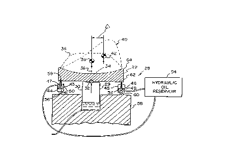
The shoe support system 28, best shown in FIG. 1, has a central
support hydraulic actuator 29 with a piston 30 which engages a
cross-machine bearing pin 32 which supports the shoe 22. The central
hydraulic actuator 29 is supported on a cross machine direction beam 58
which also supports guides 33 for the blanket 24.
The shoe support system 28 by way of the central piston 30
supplies pressure to a nip 34 formed between the backing roll 26 and the
shoe 22. The total nip pressure, as measured in Ibs. per linear inch in the
cross machine direction, is between 1,200-8,500 pli. This pressure is
distributed in the machine direction along the width of the nip 34 formed
between the shoe 22 and the backing roll 26. The pressure in the nip 34
presses water from the web 48 into the press fabrics 25, 27. FIG. 1
shows a nip load profile 36 which represents the total loading the piston 30
applies to the shoe 22 which is reacted by the backing roll 26 as shown in
FIG. 2. As required by a static analysis, the sum of the forces normal to
the nip are equal to the applied load.
If all forces are applied by the central piston 30 through the bearing
pin 32, then the moments about the pin 32 must be zero. For the
' CA 02242662 1998-07-10
7
moments to be balanced, the forces must be balanced about a vertical
plane 38 extending through the pin 32. This is the same as saying the
center of gravity 39 of the pressure profile 36 must lie above the center of
the bearing pin 32.
If a balanced force couple is used to apply a torque about the center
of the pin 32 the total load, and therefore the total area under the nip
profile curve 40 remains the same. The center of gravity 42, however, is
displaced by a distance to balance the torque.
As shown in FIG. 1, a leading hydraulic actuator 44 and a trailing
hydraulic actuator 46 are arranged to apply a pure torque about the center
of the bearing pin 32. The leading actuator 44 has a piston 41 which
moves within an actuator cylinder 43. The trailing actuator 46 has a piston
49 which moves within an actuator cylinder 45. As shown in FIG. 4 a
paper web 48 moves from left to right defining an upstream direction to
the left and a downstream direction to the right. The leading hydraulic
actuator 44 is balanced with the trailing hydraulic actuator 46 by placing
the hydraulic actuators 44, 46 equidistant from and on opposite sides of
the pivot pin 32. The forces applied by the actuators 44, 46 may be
conveniently made the same by sizing the moving surfaces 50, 52 of the
hydraulic actuator pistons 41, 49 to have identical surface areas and
connecting each the cylinders 43, 45 of each hydraulic actuator to the
same hydraulic reservoir 54 and pump (pump not shown). As is well
understood in the hydraulic art if the hydraulic pressure to two hydraulic
actuators is the same then total actuation force depends on area of the
hydraulic piston or more particularly the area normal to the direction of
motion of the moving part of the actuator which develops the actuator
force.
CA 02242662 1998-07-10
8
If the hydraulic actuators 44, 46 are as shown in FIG. 1, the leading
hydraulic cylinder 43 will have a larger diameter then the trailing hydraulic
cylinder 45 because the area of the piston rod 47 must be subtracted from
the total area of the piston on which the hydraulic fluid can act.
The leading hydraulic actuator 44 has a pivot pin or universal mount
56 attaching the actuator 44 to the support beam 58. The actuator piston
rod 47 is similarly attached to the shoe 22 by a mount 59. The trailing
hydraulic actuator 46 also has a pivotal mount 60 which mounts the
actuator 46 on the support beam 58 and a shoe mount 62 which provides
a pivotal mount between the trailing actuator 46 and the shoe 22. The
shoe 22 thus mounted is free to pivot about the pivot pin 32 in response to
the couple or torque provided by the leading and trailing hydraulic actuators
44, 46.
The pressure profile 40 shown in FIG. 1 provides a steady increase in
pressure as the web 48 moves through the nip 34 followed by a rapid drop
in pressure at the trailing edge 64 of the shoe 22. This pressure profile is
known to generally improve the performance of an extended nip press. It
improves the amount of water removal from the web and decreases the
amount of rewetting from the press fabrics. The pressure profile provides a
relatively gradual increase in pressure in the nip without causing crushing or
dislocation of the fibers. When a heated backing roll which engages the
web directly is used, the pressure profile is also important in preventing
delamination and in improving the properties of the web.
In some prior art methods of controlling nip pressure profile it was
necessary to change the position of the bearing pin 32 or it was necessary
to adjust the shape of the shoe. These operations could only be performed
while the machine was down for major maintenance. Other approaches to
adjusting the nip profile while the extended nip press was in operation
- CA 02242662 1998-07-10
9
invariably lack an ability to independently control total nip pressure and the
nip pressure profile.
Advancements in papermaking are moving in the direction of
monitoring the quality of the paper being formed and adjusting various
parameters of the papermaking machine to control web properties in
realtime or near realtime. Control algorithms and laws are easier to
understand and design if paper formation variables can be independently
varied.
It may also be observed that while science is making major
contributions to the manufacture of paper, papermaking remains an art.
This is apparent because, while individual parameters of the papermaking
process such as nip pressure profile need to be varied for different
furnishes and paper grades, the paper web being formed also benefits from
continuous adjustments to nip pressure profile in response to measured
web quality. These adjustments may be necessary although the furnish
and other parameters of the papermaking process are as nearly as possible
maintained unchanged. Thus independent control of total nip pressure, and
nip pressure profile shape carries with it the prospect of better control of
the papermaking process.
An alternative embodiment shoe support system 128 is shown in
FIGS. 2 and 3. In this system a torque is applied directly to a bearing pin
132 which is welded or fixed to a shoe 122. The torque results in the
pressure profile 136 being changed to the pressure profile 140 which has
the beneficial shape in which the pressure steadily increases from a leading
edge 141 to a pressure maximum 143 after which pressure rapidly drops
off steeply towards a trailing edge 146.
The bearing pin 132 is supported by a hydraulic actuator 130 which
has a piston 131 which bears against the pin 132. Total nip pressure as
CA 02242662 1998-07-10
defined by the area under the curve 136 and is supplied by the hydraulic
actuator 130. A torque applied to the pin 132 causes the center of gravity
of the nip pressure profile 136 to shift to the right or downstream side of
the shoe resulting in a pressure profile 140 shown in FIG. 2. FIG. 3
shows how access to the bearing pin 132 can be gained by extending the
pin out from under the shoe 122 and applying bending forces indicated by
arrows 145 to the bearing rod 132. FIG. 3 makes clear how a torque can
be applied to the bearing pin 132 and through the bearing into the shoe
122. As will be clear to those skilled in the mechanical arts, the arms 147
to which the torque is applied could be contained within the piston 131 if a
single piston is used to support a continuous shoe. On the other hand, if
multiple pistons are positioned beneath the shoe the torque-applying arms
can be positioned between the pistons.
It is understood that the invention is not limited to the particular
construction and arrangement of parts herein illustrated and described, but
embraces such modified forms thereof as come within the scope of the
following claims.