Note : Les descriptions sont présentées dans la langue officielle dans laquelle elles ont été soumises.
CA 02242664 1998-07-02
Explanations on the Creation:
Background of the Creation:
[A Brief Introduction on the Creation Technology]
This creation is a kind of "AC/DC rechargeable mobile phone cell", especially
a mobile phone
cell which can be charged directly by market power or charged by an ordinary
DC charger
available on the market.
To charge a traditional mobile phone cell for replenishing the consumed energy
a charger must
be used. For this reason, ~e user has to buy an extra charger and pay more
money. Besides, the
charger is too large and too heavy and cumbersome to carry.
[A Brief Introduction on Former Technology]
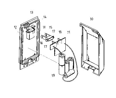
Because of these disadvantages, the manufacturers have improved it. As shown
in Fig.l, the
rechargeable cell~'is composed of a case(10) and a charger etc.. A concave
cabinet (13) with two
notches on its lefr and right is placed on the panel ( 12) o ' the case ( 10)
to hold an eversible and
locatable plug (15). The plug(15) has two forward stretched electric insertion
pieces(16) and a
conducting support axle(17) connecting the electric insertion pieces(16)
traverse. Left and right
conducting plates(18) with notches are installed an the circuit board(11 ) of
the, charger to grip the
conducting support axle(17) of the plug (15). Then the market power(AC) can be
supplied into the
charger through the electric insertion pieces( 16), conducting support axle(
17) and conducting
plate(18) of the plug(15). But this design of the conducting support axle(17)
will increase current
resistance; in addition, the contac's between the conducting support axle(17)
and the conducting
plates(18} of the circuit board(11) is in fast coupling form, which cannot be
firmly contacted
Besides, when the plug(15) is everting and locating as well as retracting and
settling, the
CA 02242664 1998-07-02
conducting support axle(I7) is not detached from the conducting plate(18), it
always courses
abrasion and result in lowering conductivity. Even more, because the
positioning of the
conducting support axle( 17) of the plug ( 15) is based on the firm assembly
of the circuit board( 11 )
and the supporting of the conducting plate(18), looses always occur. This is
not an ideal structure
for operation.
Another shortcoming is: Plug(15) is the AC input terminal of the charger.
After rectifying,
filtering and stabilizing, the AC is converted into DC to drive the
transformer and charging circuit
through a driving circuit composed of transistors. The DC, on the one hand, is
used to charge the
rechargeable cell(19), on the other hand, supplies energy to the mobile phone
through the DC
output terminals of the panel(12). When the cells(19) are full charged, the
charger cannot shut
down the driven circuit automatically. It will result in energy wasting and
life-time shortening of
the circuit and cells(19). Another problem is that there is no indicator for
full charging and no
overheating protection for the cells(19).
Because of the disadvantages of the existed rechargeable mobile phone cell, I
have been
looking for a new way to solve these problems and finally completed the
creation "AC/DC
rechargeable mobile phone cell".
The purpose of this creation is to provide an "AC/DC rechargeable mobile phone
cell". Its
plastic axle of the plug is held between the concave cabinet of the panel and
back case body,
making plug's electric insertion piece to press closely on the elastic
conducting pieces of the
charger circuit board. When the plug is retracted and settled, the electric
insertion pieces will be
detached from the elastic conducting pieces. It can be fast and firmly
assembled as a whole. It is
durable and its conducting quality is improved.
Another purpose of this creation is to provide'an "AC/DC rechargeable mobile
phone cell". An
eversible and locatable plug is placed on the back of the case body, making
the rechargeable cell
can be directly charged by the market power without detaching from the mobile
phone.
The third purpose of the creation is to provide an "AC/DC rechargeable mobile
phone cell". A
dual-color LED, a thermal sensitive resistor and the rechargeable cells are
connected parallel
across the charging circuit. When the charging voltage is lower then the
reference voltage, the red
light of ~e dual LED is lit up. When the cells are fully charged, the green
light of the dual LED is
Iit up and a low potential is output to an optic_coupling switch from a linear
IC to stop recharging.
Accordingly, the energy is saved and the cell's life is prolonged.
For the purpose of appraisal, a practical example with pictures is introduced
in detail as follows
to explain how to realize the above target by using technology measures.
[Figures Explanations]
Fig. l : Partition view of an ordinary rechargeable mobile phone cell.
Fig.2: Appearance of my creation.
Fig.3: Partition view of Fig.2
2
CA 02242664 1998-07-02
Fig.4: Partition view showing the plug(in Fig.2) has been evened and located.
Fig.S: Section view showing the plug(in Fig.4) has been evened and located.
Fig.6: Side view of Fig.S
Fig.7: Showing the plug in Fig.6 has been retracted and settled.
Fig.B: Block diagram of the charger of this creation.
Fig.9: Circuit diagram of Fig.B
Fig.10: Appearance of another practical example of this creation.
[Parts explanation]
(20) Panel (21) Back (23) Side wall
case body (22) Concave
cabinet
(24) Side wall (25) (26) Supporting (27) Supporting
Notch plate plate
(28) Notch (29) Light (210) Back case (220) Concave
window body cabinet
(30) Plug (31 ) Plastic(32) Supporting (33) Supporting
body axle axle
(34) Electric insertion(35) Electric
piece insertion piece
(40) Elastic power (42) Elastic charging
supply piece (41 ) piece
Elastic power supply
piece
(50) Circuit board (52) Elastic conducting
(51) Elastic conducting piece
piece
(60) AC input terminal(61 ) Rectifying (62) Filtering
circuit circuit
(63) Voltage stabilizing(64) Driving circuit(65) Charging
circuit circuit
(66) Overheating protection(67) Rechargeable
circuit battery
(68) DC output terminal(69) DC input
terminal
As indicated in Fig.2, the creation "AC/DC rechargeable mobile phone cell" is
mainly a
rechargeable mobile phone cell which can be directly charged by market
power(AC 110-240V
generally). A charger is fixed in a case, and a concave cabinet (22) space is
formed on the from of
the panel(20) of the case to hold the plug (30) ( can be evened and located as
well as retracted and
settled) which is used for directly charging with the market power.
As indicated in Fig.3, the case of the rechargeable cell is composed of the
panel(20) and back
case body(21 ) by connecting them with high-frequency fusion joining. A
concave cabinet(22)
space is made on the front of the panel(20). notches (25) are made
respectively at the rear ends of
the left and right side walls(23x24) of the concave cabinet(22) to fit the
left and right sections of
the plastic support axle(32)(33) of the plastic body(31 ) of the plug(30). The
left and right electric
insertion pieces(34~35) of the plug nm through the plastic body(31) (longer in
front, shorter in
rear). A pair of plastic supporting pIates(26x27) are placed on the inner side
of the back case body
oppositely each other with one an the left, the other on the right. The
plastic supporting plates grip
the supporting axle(32x33) of the plug with their notches(28) located at the
front end of the plates
to enable the plug(30) can be evened and located ar retracted and settled
around the axle.
The charger circuit board(50) and rechargeable cells(67) are firmly installed
in the case of the
rechargeable cell. Two elastic conducting pieces(51)(52) stretch out of the
circuit board (50) are
used as AC input terminals. The rear ends of the electric insertion
pieces(34)(35) of the plug(30)
are elastically pressed on the pieces(51 )(52). Fig.4,5,6 show that the
plug(30) is in everted and
located position. The plastic body (31} of the plug (30)matches the left and
right walls(23x24) of
the concave cabinet(22). The plastic supporting axle(32)(33) is gripped and
held by a supporting
3
CA 02242664 1998-07-02
plate(26)(27) and its notches(25)(28) with the same material. This method can
reduce electrical
resistance, improve current conducting quality as a result, the AC current can
run into the charger
through the electric insertion pieces(34)(35) of the plug(30) and elastic
conducting pieces(51 X52)
smoothly. In addition, it is durable and can be assembled fast and firmly.
As indicated in Fig.7, when the rechargeable cell needs not to be charged, you
may retract and
settle the plug(30) into the concave cabinet(22) space of the panel (20), then
the rear ends of the
electric insertion pieces(34)(35} of the plug(30) will detached from the
elastic condu~ng
pieces(51 x52) of the circuit board(50).
As indicated in Fig.B, AC110-240V power enters the AC input terminal(60) of
the rechargeable
cell, and then goes through the rectifying circuit(61), filtering circuit(62}
, voltage stabilizing
circuit(63), driving circuit(64) and charging circuit(65) to charge the
rechargeable cells(67). When
using market charger, the charging current runs through the DC terminal(69)
and elastic charging
piece(42) ( as indicated in Fig.3) into rechargeable cells(67). When the
rechargeable cells are fully
charged, you may switch the DC into the mobile phone through its DC output
terminal (68) and
the conducting piece(40) as indicated in Fig.3.
Please refer to Fig. 9: The AC 110-240V power enters the AC input terminal{60)
of the charger,
then rectified into DC current through a bridge connected rectifier (D 1 ) of
the rectifying
circuit{61 ). The current limiting resistor(Rl ) is used to limit the ciurent
within a definitive range;
the resistor(R2) and diode(D2) combined with the transistor(Q1) are used as a
filter, and together
with a Zener diode(D3) in the voltage stabilizing circuit provide a comparing
reference voltage for
the over current protection seckion in the driving circuit.
A switching circuit , which provides a proper voltage to control the
transistor(Q2), is composed
of a transistor(Ql) and an optical coupler(E1). The rechargeable cells(67} are
charged through the
transformer(T) and charging circuit(65). The charging circuit(65) is connected
to the output
terminal of the transformer's secondary coil. The following elements are
connected in the
charging circuit(65) paralelly: a dual color LED, a capacitor(E4) serially
connected with a
diode{D4), and the rechargeable cells(67). Through a Zener diode (D5) and
resistor (R7), a linear
IC(EZ) is connected at the connecting point of the capacitor(C4) and diode(D4)
to provide a
reference voltage. Ano;her end of the linear IC(E2) is connected to the cross-
over point of the dual
color LED to compare the charging voltage with the reference voltage. While
the voltage is lower
than the reference voltage (tee potential of pin #3 lower than that of pin
#2), the driving circuit(64)
is driven to work, and the rechargeable cells(67) is charged through the
transformer(T) and the
charging circuit(65). At the same time, the dual color LED (refer to the light
window(29) in Fig.3)
is lit up with red color, showing it is charging. When the rechargeable cells
are fully charged
the potential of pin #2 lower than that of pin #3), the diode(D4) is conducted
and the dual LED is
lit up with green color. At the same time, a lower potential is output to the
optical switch IC(E 1 )
from the linear IC(E2) to cut-off the transistor(Q2) and stop charging. As a
result, the energy is
saved and the life of the circuit and cells is prolonged.
Before the rechargeable cells(67) is connected to the output terminals of the
transformer(T)'s
4
CA 02242664 1998-07-02
secondary side, two thermal sensitive resistors (R10),(R11) of an over-heating
protection
circuit(66) are serially connected with it. While the temperature inside the
rechargeable cell(67) is
rising, the resistance of the thermal sensitive resistors (R10), (Rl 1 ) is
going down
correspondingly, which provides an over-heating protection to stop charging
the rechargeable
cells.
As indicated in Fig.lO, the concave cabinet(220) is placed on the back of the
case(210) to hold
the plug(30) making the rechargeable cell to be charged by the market power
without detaching it
from the mobile phone.
In summary, the " AC/DC rechargeable mobile phone cell" is durable and can be
assembled
fast and firmly; its conductivity is higher than the others; suitable for
charging a standby mobile
phone; it has indicators for displaying the charging conditions (charging or
fully charged); it can
stop charging automatically, as a result, the life-time of the circuits and
rechargeable cells are
prolonged. It can meet all requirements in practice. I hereby submit the
application for a New
Type Patent.