Note : Les descriptions sont présentées dans la langue officielle dans laquelle elles ont été soumises.
CA 022431~6 1998-07-1~
METHOD OF MANUFACTURING MOLDED BAKED SNACKS
TECHNICAL FIELD
The present invention relates to a method of
manufacturing edible molded objects made of flour, etc.
BACKGROUND ART
. An example of edible molded objects made of flour
and other ingredients are molded baked snacks such as ice
cream cones, monaka, wafers, etc. One method of
manufacturing this kind of molded baked snack is the
external heating method, in which the ingredients are
placed into a mold previously heated to a predetermined
temperature, and the snack is molded by heat
conductivity.
However, with methods of this kind, slow molding
leads to low productivity, and unevenness in the
CA 022431~6 1998-07-1
-- 2
temperature of the mold causes uneven baking, thus making
it impossible to obtain a uniform consistency when eaten,
which varies from part to part.
For this reason, in another method, alternating
current is supplied to a metal mold, and internal heating
is induced in the ingredients in the mold by
electromagnetic wave heating, such as resistance heating
or dielectric heating, thereby baking and molding the
ingredients. In this case, the metal mold is divided into
two mold halves, which are insulated from each other by
an insulating material provided therebetween, and an
alternating current electrode is connected to each mold
half. Then alternating current is applied to the metal
mold through these electrodes, and the ingredients in the
mold are baked and molded by resistance heating or
dielectric heating.
However, with the foregoing method using resistance
heating or dielectric heating, during molding, liquid
contained in the ingredients evaporates, producing a
large amount of vapor, which condenses, causing
insulation breakdown, and thus resistance heating or
dielectric heating does not go well.
DISCLOSURE OF THE INVENTION
The object of the present invention is to provide a
CA 02243156 1998-07-1~
method of manufacturing molded baked snacks capable of
preventing insulation breakdown due to condensation of a
large amount of vapor evaporating from the ingredients
during heating and molding of the molded baked snacks by
resistance heating or dielectric heating.
In order to attain the foregoing object, a first
method of manufacturing molded baked snacks according to
the present invention is a method of manufacturing molded
baked snacks by placing ingredients in a mold made up of
first and second conductive mold halves and an insulating
section therebetween, and applying across both mold
halves alternating current from an alternating current
power source, thus heating and expanding the ingredients
by means of resistance heating and/or dielectric heating,
in which the insulating section of the mold is provided
with a vapor release section, pressure is reduced outside
the mold, and the heating is performed while releasing
vapor produced thereby through the vapor release section.
During heating and molding of the molded baked
snacks, a large amount of vapor is produced, and this
vapor condenses in the vapor release section provided in
the insulating section, causing insulation breakdown.
However, with the foregoing method, by reducing pressure,
condensation of the vapor is prevented. Consequently,
insulation breakdown can be prevented.
CA 022431~6 1998-07-1~
A second method of manufacturing molded baked snacks
is a method of manufacturing molded baked snacks by
placing ingredients in a mold made up of first and second
conductive mold halves and an insulating section
therebetween, and applying across both mold halves
alternating current from an alternating current power
source, thus heating and expanding the ingredients by
means of resistance heating and/or dielectric heating, in
which the insulating section of the mold is provided with
a vapor release section, the vapor release section is
heated, and the heating of the ingredients is performed
while releasing vapor produced thereby through the vapor
release section.
During heating and molding of the molded baked
snacks, a large amount of vapor is produced, and this
vapor condenses in the vapor release section provided in
the insulating section, causing insulation breakdown.
However, with the foregoing method, by heating the vapor
release section, condensation of the vapor is prevented.
Consequently, insulation breakdown can be prevented.
Additional objects, features, and strengths of the
present invention will be made clear by the description
below. Further, the advantages of the present invention
will be evident from the following explanation in
reference to the drawings.
CA 022431~6 1998-07-1~
BRIEF DESCRIPTION OF THE DRAWINGS
Figure 1 is an explanatory drawing showing one
structural example of a heating device for a method of
manufacturing molded baked snacks according to the
present invention.
Figure 2 is an explanatory drawing showing another
structural example of a heating device for a method of
manufacturing molded baked snacks according to the
present invention.
Figure 3 is an explanatory drawing showing a further
structural example of a heating device for a method of
manufacturing molded baked snacks according to the
present invention.
Figure 4 is an explanatory drawing showing a further
structural example of a heating device for a method of
manufacturing molded baked snacks according to the
present invention.
Figure 5 is a graph showing transition in the anode
current of an oscillator during heating.
Figures 6(a) through 6(c) show one structural
example of an insulating body; Figure 6(a) is a
horizontal sectional view, Figure 6(b) a side view, and
Figure 6(c) a cross-sectional view taken along line F-F
of Figure 6(a).
Figures 7(a) through 7(c) show another structural
CA 022431~6 1998-07-1~
example of an insulating body; Figure 7(a) is a
horizontal sectional view, Figure 7(b) a side view, and
Figure 7(c) a cross-sectional view taken along line G-G
of Figure 7(a).
Figure 8 is an explanatory drawing showing a
structural example of a metal mold.
Figure 9 is an explanatory drawing showing another
structural example of a metal mold.
Figure 10 is a cross-sectional view showing one
example of a method of installing an insulating body.
Figure 11 is a cross-sectional view showing one
example of a method of providing an insulating section of
air, without installing an insulating body.
Figures 12(a) and 12(b) show one structural example
of a molded baked snack; Figure 12(a) is a plan view, and
Figure 12(b) a cross-sectional view taken along line J-J
of Figure 12(a).
Figures 13(a) and 13(b) show another structural
example of a molded baked snack; Figure 13(a) is a plan
view, and Figure 13(b) a cross-sectional view taken along
line K-K of Figure 13(a).
Figures 14(a) and 14(b) show a further structural
example of a molded baked snack; Figure 14(a) is a plan
view, and Figure 14(b) a cross-sectional view taken along
line L-L of Figure 14(a).
CA 022431~6 1998-07-1~
Figures 15(a) and 15(b) show a further structural
example of a molded baked snack; Figure 15(a) is a plan
view, and Figure 15(b) a cross-sectional view taken along
line M-M of Figure 15(a).
Figure 16 is a plan view showing a further
structural example of a molded baked snack.
Figure 17 is a plan view showing a further
structural example of a molded baked snack.
Figure 18 is an explanatory drawing showing one
example of a method of measuring the strength of a molded
baked snack.
Figure 19 is an explanatory drawing showing another
example of a method of measuring the strength of a molded
backed snack.
Figure 20 is an explanatory drawing showing one
example of a method of measuring a molded baked snack's
consistency when eaten.
Figures 21(a) and 21(b) show one structural example
of a molded baked snack; Figure 21(a) is a cross-
sectional view, and Figure 21(b) a plan view.
Figure 22 is an explanatory drawing showing the
state of a cross-section of a molded baked snack
manufactured by internal heating.
Figure 23 is an explanatory drawing showing the
state of a cross-section of a molded baked snack
CA 022431~6 1998-07-1
manufactured by external heating.
Figure 24 is a graph showing the relationship
between amperage and heating time of molded baked snacks.
Figure 25 is a graph showing the relationship
between amperage and heating time of molded baked snacks.
Figure 26 is a graph showing the relationship
between amperage and heating time of molded baked snacks.
Figure 27 is a graph showing the relationship
between amperage and heating time of molded baked snacks.
Figure 28 is a graph showing the relationship
between amperage and heating time of molded baked snacks.
Figure 29 is a graph showing the relationship
between amperage and heating time of molded baked snacks.
Figure 30 is a graph showing the relationship
between amperage and heating time of molded baked snacks.
Figure 31 is a graph showing the relationship
between amperage and heating time of molded baked snacks.
Figure 32 is a graph showing the relationship
between amperage and heating time of molded baked snacks.
Figure 33 is a graph showing the relationship
between amperage and heating time of molded baked snacks.
Figure 34 is a graph showing the relationship
between amperage and heating time of molded baked snacks.
Figure 35 is a graph showing the relationship
between amperage and heating time of molded baked snacks.
CA 022431~6 1998-07-1~
BEST MODE FOR CARRYING OUT THE INVENTION
The following will explain embodiments of the
present invention with reference to Figures 1 through 35.
First, structures common to all of the embodiments will
be discussed.
(INGREDIENTS)
The ingredients used in the present invention are
shown in Tables 1 through 6.
TABLE 1
INGREDIENT 1 2 3 4 5 6
MIXTURE NO.
FLOUR 100100 100100 100100 100
STARCH 20 20 20 20 20 20 20
SALT 0 0.2 0.5 1 2 5 10
SUGAR 5 5 5 5 5 5 5
FLAVORING 0 0 0 0 0 0 0
LEAVENING0.50 5 0 50-5 0 50 5 0-5
COLORING
AROMATIC
OIL/EMULSIFIER 2 2 2 2 2 2 2
TOTAL SOLIDS129.5 129.7130.0 130.5 131.5 134.5 139.5
WATER 130130 130130 130130 140
PROPORTION OF 49.90 49.94 50.00 50.10 50.29 50.85 49.91
SOLIDS (~
VISCOSITY (CP)270026003000 2700 2800 2800 2500
CA 022431~6 1998-07-1~
-- 10
TABLE 2
INGREDIENT MIXTURE 8 9 10 11 12 13 14 15
NO.
FLOUR 100 100 100 100 100 100 100 100
STARCH 20 20 20 20 20 20 20 20
SALT 0.5 0.5 0 5 0.5 0.5 0.5 o 5 o 5
SUGAR 5 5 5 5 5 5 5 5
FLAVORING 5 5 5 5 5 5 5 5
LEAVENING 0.5 0.5 0.5 0.5 0.5 0.5 0.5 0.5
COLORING
AROMATIC
OIL/EMULSIFIER 2 2 2 2 2 2 2 2
TOTAL SOLIDS 135 135 135 135 135 135 135 135
WATER 70 90 110 140 170 190 210 230
PROPORTION OF 65.8560.00 55.1049.0944.26 41.54 39.13 36.99
SOLIDS (~)
VISCOSITY (CP)DOUGH11000 60002500 1500 900 600 300
CA 022431~6 1998-07-1
TABLE 3
IN5REDIENT16 3 17 18 19 20 21
MIXTURE NO.
FLOUR 100 100 100 100 100 100 100
STARCH 10 20 50 100 150 20 20
PULVERIZED
PREVIOUSLY MOLDED 0 0 0 0 0 10 20
SNACKS
SALT 0.5 0 5 0.5 0.5 0 5 o 5 o 5
SUGAR 5 5 5 5 5 5 5
FLAVORING 0 0 ~ ~ ~ ~ ~
LEAVENING 0.5 0.5 0.5 0.5 0.5 0.5 0.5
COLORING
AROMATIC
OIL/EMULSIFIER 2 2 2 2 2 2 2
TOTAL SOLIDS 120 130 160 210 260 140 150
WATER 120 130 160 210 260 140 150
PROPORTION OF 50.0050.0050.0050.0050.0050.00 50.00
SOLIDS (~)
VISCOSITY (CP)2700 3000 2800 2800 2800 4000 6500
CA 02243l~6 l998-07-l~
- 12
TABLE 4
INGREDIENT MIXTURE 22 11 23 24 25 26
NO
FLOUR 100 100 100 100 100 100
STARCH 20 20 20 20 20 20
SALT 0.5 0.5 0.5 0.5 0.5 0.5
SUGAR 2 5 10 20 40 60
FLAVORING 5 5 5 5 5 5
LEAVENING 0.5 0 5 0.5 o 5 o 5 o 5
COLORING
AROMATIC
OIL/EMULSIFIER 1 2 2 2 4 4
TOTAL SOLIDS131 135 140 150 172 192
WATER 130 140 140 150 170 190
PROPORTION OF SOLIDS 50.3849.09 50.0050.00 50.00 50.00
(~)
VISCOSITY (CP) 3500 2500 2700 2B00 3200 3300
CA 022431~6 1998-07-1
TABLE 5
INGREDIENT MIXTURE NO. 27 28 29 24 30
FLOUR 100 100 100 100 100
STARCH 20 20 20 20 20
SALT 0.5 0.5 0.5 0.5 0.5
SUGAR 20 20 20 20 20
FLAVORING 5 5 5 5 5
LEAVENING 0.5 0.5 0.5 0.5 0.5
COLORING
AROMATIC 0.1 0.2 0.5 1 2
OIL/EMULSIFIER 2 2 2 2 2
TOTAL SOLIDS 149.1 149.2 149.5 150 151
WATER 150 150 150 150 150
PROPORTION OF SOLIDS (~) 49.85 49.87 49.92 50.00 50.17
VISCOSITY (CP)2600 2800 2600 2800 3000
CA 02243l~6 l998-07-l~
-- 14
TABLE 6
INGI~EDIENTMIXTURE31 32 33 34 35 36
NO.
FLOI~R 100100 100100 100100
STARCH o o o o o
SALT 0 50.5 0.50.5 0.50.5
SUGAR 5 5 5 5 5
FLAVORING 0 0 0 0 0 0
LEAVENING 0 0.1 0.20.5 1 2
COLORING
AROMATIC
OIL/EMULSIFIER 2 2 2 2 2 2
TOTAL SOLIDS 109.5109.6 109.7 110 110.5 111.5
WATER 110110 110110 110110
PROPORTION OF SOLIDS49.8949.91 49.93 50.00 50.11 50.34
(~)
VISCOSITY (CP)32003300 32003300 3500 3800
By varying the quantity of salt added, as shown in
Table 1, the conductivity of the ingredients changes, and
this influences molding by internal heating. By changing
the quantity and type of salt, conductivity can be
controlled. Control of conductivity is definitely
necessary in low-frequency heating.
As the proportion of solids increases, as shown in
Table 2, the molded baked snack produced tends to be
harder, with a harder consistency when eaten. Hardness
may be varied in keeping with the shape and use of the
target molded and baked snack. Incidentally, the
CA 022431~6 1998-07-1~
ingredient mixtures shown in Table 2 include various
amounts of water, and have a wide range of viscosities,
but, if an appropriate depositing (injection) structure
is used, each of these ingredient mixtures can be molded
in each of the metal molds used in the present invention.
By adjusting the quantity and type of starch, as
shown in Table 3, a required expansion, shape,
consistency when eaten, etc. can be realized.
Incidentally, previously molded snacks which have been
defectively molded, and burr portions, may be reused
after refining and grinding.
By adjusting the quantity of sugar, as shown in
Table 4, a required expansion, shape, consistency when
eaten, flavor, etc. can be realized.
In Table 5, a small quantity of aromatic is
sufficient in molding by internal heating.
In Table 6, a small quantity of leavening is
sufficient in molding by internal heating.
Ingredient mixtures No. 1 through No. 36 set forth
in Tables 1 through 6 are used as ingredients in the
present invention.
For the flour, strong flour, medium flour, weak
flour, or a mixture of these is used.
For the starch, potato starch, wheat starch, rice
starch, cornstarch, tapioca starch, sweet potato starch,
CA 022431~6 1998-07-1
- 16
etc., or a crosslinked starch of these is used.
"Pulverized previously molded snacks" are snacks
which have already been molded, and have then been
refined and ground, or are burrs protruding from between
the mold halves, which have been collected and ground.
For the salt, any edible salt may be used, and thus
NaC1 (sodium chloride), KCl (potassium chloride), L-
sodium tartrate, ammonium chloride, sodium lactate,
sodium polyphosphate, sodium metaphosphate, etc. are
used.
For the sugar, granulated sugar, powdered sugar,
brown sugar, malt syrup, sugar alcohol (sorbitol,
glycerin, propylene glycol), etc. are used.
For the flavoring, milk products (butter, whole
milk, skim milk), eggs (eggs, powdered whole eggs,
powdered egg yolks), cacao, coffee, nuts (almonds,
peanuts, coconut), bread crumbs, corn grits, fruit juice,
etc. are used.
For the leavening, sodium bicarbonate, alum, any
kind of baking powder, etc. are used.
For the coloring, food colorings such as caramel,
cochineal, carotene, annatto, etc. are used.
For the aromatic, food aromatics such as vanilla
extract, butter flavoring, etc. are used.
For the oil or emulsifier, vegetable oils such as
CA 02243156 1998-07-1~
soybean oil, rapeseed oil, corn oil, etc., or emulsifiers
such as soy lecithin, fatty acid esters, etc. are used.
For each of the ingredients, one or several of the
examples listed above may be used.
(PREPARATION OF INGREDIENTS FOR MOLDING)
The process of the present invention, from
preparation of ingredients through molding, is as
follows.
(1) Measuring of ingredients.
(2) Mixing of water and ingredients other than those in
(3) and (4) below in a mixer.
(3) Mixing in of flour and starch.
(4) Mixing in of oil.
(5) Ageing.
(6) Depositing (injection).
(7) Placing in mold and molding.
The molded baked snacks are prepared by means of the
foregoing steps.
(DEVICES)
Next, the devices used in the present invention will
be explained. Since the mixers, etc. used were equivalent
to conventional ones, explanation thereof will be
omitted. The molded baked snacks were prepared by placing
the foregoing ingredients in a mold to be discussed
below, and then heating and expanding in a heating
CA 022431~6 1998-07-1
- 18 -
device. For the heating device, a total of four devices
were used: three types of electromagnetic wave heating
devices (referred to as "HB, " "HC, " and "HD" ), and, for
purposes of comparison, an external heating device
(referred to as "HA" ) . The structural details of each of
these heating devices are as shown in Table 7 below.
Further, the schematic structures of electromagnetic wave
heating devices are shown in Figures 1 through 4.
Incidentally, the frequency used is not limited to that
shown in Table 7; an appropriate frequency within a range
from 5 OHz through 10 OMHz may be used.
TABLE 7
HEATING DEVICBPRIMARY POWER FREQUENCY ~UI~v~ r;K OUTPUT REGULATOR ELECTRODES INSULATION TEMPERATURE
SOURCE ADJUSTMENT
HA: EXTERNAL HEATING 60Hz, 200VNONE NONE PROVIDED NONE NONE 150~C TO 230~C
INTERNAL HB: 50Hz TO 60Hz, 200VWITHIN 50HZ TO 10kHz PROVIDED METAL MOLD BASICALLY 50~C TO 230~C
HEATING lMHz RANGE MADE OF Al PRESENT D
HC: lMHz TO 60Hz,200VTHREE TYPES WITHIN lMHzPROVIDED IN METAL MOLD BASICALLY 50~C TO 230~C
100MHz TO 100MHZ RANGEOSCILLATOR AREAMADE OF Al PRESENT
WITHIN 50Hz TO 10kHz PROVIDED IN
HD: BOTH HB 60Hz,200V RANGE OSCILLATOR AREA METAL MOLD BASICALLY 50~C TO 230~C , ~D
AND HC USED MADE OF Al PRESENT
THREE TYPES WITHIN lMHz PROVIDED IN ~~
TO 100MHz RANGEOSCILLATOR AREA I_
CA 022431~6 1998-07-1
- 20 -
Device HB includes three types: HB1, HB2, and HB3.
Device HC also includes three types: HC1, HC2, and HC3.
Here, the power source for the devices HA, HB, HC,
and HD is an industrial power source with a voltage of
200V and a frequency of 6OHz.
The output regulators of devices HB, HC, and HD are
devices which regulate output to a desired constant
output.
The frequency converters of devices HB, HC, and HD
are devices which output frequency converted to a desired
frequency within a specified range.
The oscillators of devices HC and HD are devices
which oscillate at a specified frequency only. However,
in the case of device HB, there is a frequency zone for
which an oscillator is unnecessary. In other words,
device HB1 uses a frequency of 60Hz, HB2 a frequency of
200Hz, and HB3 a frequency of lO.OkHz, but an oscillator
is unnecessary in each of these cases. Using oscillators,
device HC1 uses a frequency of 5.0MHz, HC2 a frequency of
13.56MHz, and HC3 a frequency of 40.68MHz. Device HD uses
a combination of the foregoing oscillators.
The electrodes of devices HB, HC, and HD are devices
for supplying high- or low-frequency current to the
ingredients through the mold.
In devices HA, HB, HC, and HD, temperature
CA 02243l~6 l998-07-l~
-- 21
adjustment refers to adjustment of the temperature of the
metal mold, prior to molding, using an electric heater
installed in the metal mold, or directly heating the
metal mold externally using a gas burner, or using IH
(induction heating) to heat the metal mold, etc. Without
this kind of temperature adjustment, the temperature of
the metal mold is within a range up to 100~C.
The following will explain the individual structures
of the foregoing electromagnetic wave heating devices.
As shown in Figure 1, an electromagnetic wave
heating device 1 includes a power section 2 and a heating
section 3 (electrode section). Further, although not
shown in the drawing, the heating section 3 includes a
vacuum pump, a lock section which fixes the upper and
lower mold halves, and an external heating section.
When the frequency is 5MHz, 13.56MHz, or 40.68MHz,
the power section 2 uses for a power source an oscillator
4 of the vacuum tube type. Energy efficiency is
determined by the output of the oscillator 4. Mold halves
8a and 8b (to be discussed below) must not come into
direct contact with one another, and thus an insulating
section is provided therebetween. An insulating body 8c
is used for the insulating section. The insulating
section is for preventing the mold halves 8a and 8b from
touching one another, and may be provided as a space. In
CA 022431~6 1998-07-1
- 22
addition, each of the necessary devices should be
provided with a ground and an electromagnetic wave
shield.
Further, as a regulating circuit, a variable
capacitor (referred to as "C component") 5 and a variable
coil (referred to as "L component") 6 are provided. By
changing the C component 5 and the L component 6
according to the object to be heated, optimum output and
tuning can be obtained. As the C component 5, a manual
capacitor C1 (referred to as the "C1 component") is
provided.
In the device shown in Figure 2, the side with the
mold half 8a, having more pointed areas such as the apex
8al (in Figure 2 , the upper side), is grounded. When one
of the mold halves 8a has pointed areas of this kind, if,
as shown in Figure 1, the mold half 8a is connected to
the power source and the other mold half 8b is grounded,
energy from the power source tends to concentrate in the
pointed area, and thus localized heating of an apex area
9c of the ingredients 9 is likely to occur. For this
reason, if a mold half 8a having a pointed area, as shown
in Figure 2, iS grounded, energy from the power source
can be prevented from concentrating in the pointed area,
and it is easier to prevent localized heating than with
the device shown in Figure 1.
CA 022431~6 1998-07-1~
By providing, as shown in Figure 3, an automatic
capacitor C2 (referred to as the "C2 component") as a
variable capacitor for automatic regulation and tuning,
anode current in the oscillator vacuum tube can be
controlled to a constant value. This anode current is
controlled by an automatic tracking circuit. The
automatic tracking circuit is a circuit which can
automatically change an interval between the plates of an
air capacitor using a motor, and which maintains a
constant anode amperage in accordance with changes in the
dielectric constant across the two electrodes of the
heating section 3.
Here, increasing (or decreasing) the interval
between the plates of the capacitor making up the C
component will be referred to as "widening (or narrowing)
the C component," and lengthening (or shortening) of the
L component resistor length actually used in the circuit
will be referred to as "lengthening (or shortening) the
L component." The wider the C component, the smaller the
output. When the manual capacitor Cl is at its narrowest,
C1=100, and when at its widest, C1=0. When the automatic
capacitor C2 is at its narrowest, C2=10, and when at its
widest, C2=0. The longer the L component, the smaller the
output. When L is at its shortest, L=O, and when at its
longest, L=15. Here, C component and L component values
CA 022431~6 1998-07-1
- 24 -
will be expressed as a proportion of their respective
minimum and maximum values.
When the automatic capacitor C2 is in operation,
the transition in the anode amperage of the oscillator is
as shown at curve A in Figure 5. In other words, the
amperage can be supplied in a constant quantity. The
automatic function of the automatic capacitor C2 can also
be turned off, and the amperage can be set manually. When
the automatic function is turned off, the transition is
as shown at curve B in Figure 5. In other words, the
amperage changes according to the conductive and
dielectric properties of the object to be heated.
When the frequency is 60Hz, 200Hz, or lOkHz, as
shown in Figure 4, an output regulator 22 is connected to
a power source 21 of 200V, and current is supplied to the
heating section 3 at a predetermined frequency by a
frequency converter 23. A transformer can be used as the
output regulator 22.
As shown in Figure 1, the heating section 3 includes
upper and lower electrodes 7a and 7b. To the electrodes
7a and 7b are connected an upper mold half 8a and a lower
mold half 8b, respectively. The mold halves 8a and 8b are
pressed together with the insulating body 8c
therebetween, and thus do not touch one another. The mold
halves 8a and 8b and the insulating body 8c make up a
CA 022431~6 1998-07-1~ -
metal mold 8. The metal mold 8 and the ingredients 9 will
collectively be referred to as the "object to be heated."
The object to be heated is placed between the electrodes
7a and 7b, to which current is supplied.
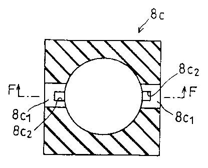
Figure 6 shows one example of a method of releasing
vapor. An insulating body 8c is provided with vapor
release sections 8cl and vapor release sections 8c2 for
releasing vapor produced during heating. Vapor produced
by the ingredients 9 (not shown) in the metal mold 8
during heating passes through the vapor release sections
8c2 to the vapor release sections 8cl, from which it is
released to the exterior of the metal mold 8. As an
alternative to the structure shown in Figure 6, a
structure like that shown in Figure 7 may also be used,
in which a plurality of vapor release sections 8c2 (for
example eight) are provided in a circular vapor release
section 8cl.
The number of vapor release sections 8c2 is usually
at least two, for the sake of balance. Further, the size,
shape, number, etc. of the vapor release sections 8cl and
the vapor release sections 8c2 are adjusted to those most
suitable to the molded baked snack to be produced. These
must be changed as necessary in keeping with changes in
the ingredient mixture and the properties of the molded
baked snack to be produced. In the present invention, it
CA 022431~6 1998-07-1
- 26
is satisfactory if the vapor is released from the
ingredients 9 to the exterior of the metal mold 8 in a
balanced manner, and thus there is no particular
limitation on the shape, size, and number of vapor
release sections. Incidentally, Figures 6 and 7 show
structures in which the vapor release sections 8c1 and 8c2
are provided in the insulating section, but, in order to
mold the entirety uniformly and efficiently, vapor
release sections may also be provided, as necessary, in
places other than the insulating section.
As shown in Figures 1 and 2, one of the two
electrodes 7a and 7b is a feed electrode, and the other
a grounding electrode. In the arrangement shown in Figure
1, the electrode 7a is the feed electrode, and electrode
7b the grounding electrode. In Figure 2, the electrodes
are connected in the opposite manner.
Although not shown in the drawing, the heating
section 3 is provided with an electric heater and a
temperature regulator, and thus the metal mold 8 can be
heated at a predetermined temperature. Incidentally, when
using external heating alone, current is not supplied
from the power section 2, and heating and molding are
performed by this heater alone.
The entirety of the heating section 3 is a vacuum
chamber, and, using the aforementioned vacuum pump, the
CA 022431~6 1998-07-1
pressure therein can be reduced.
The metal mold 8 is fixed between the electrodes 7a
and 7b using the vertical press method shown in Figure 8.
Alternatively, as shown in Figure 9, a method may be
adopted in which a hinge 25 is provided at one end of the
mold, and the other end can be locked (fixed).
(MOLD)
The following will explain the structure of the
metal mold 8, which serves as the mold into which the
ingredients are placed.
As shown in Figures 10(a) and lO(b), the metal mold
8 is basically divided into two blocks. Although not
shown in the drawings, depending on the shape of the
molded baked snack and the method of removal, a metal
mold made up of three or more parts, such as a split mold
or one provided with a knockout pin, may be used, but
even in these cases, the parts are grouped into two
blocks: a feed electrode side and a grounding electrode
slde .
The parts of each group have sections which fit
together closely when the mold is fixed and molding is
performed. Between the one block (the mold half 8a side)
and the other block (the mold half 8b side), a space for
molding of the molded baked snack and an insulating
section (here, the insulating body 8c) are provided. As
CA 022431~6 1998-07-1
- 28 -
shown in Figures 10(a) and 10(b), the insulating body 8c
can be attached to either block, or it can be attached to
both blocks.
Further, as shown in Figures ll(a) and ll(b), the
insulating section may be provided by means of a space 8d
between the mold halves 8a and 8b, without using an
insulating body. In this case, the range of the interval
of the space 8d is no less than 0.3mm and no more than
one-half the thickness of the baked molded snack. If the
interval is less than 0.3mm, insulation breakdown is
likely, and sparking makes molding impossible. On the
other hand, if the interval is more than one-half the
thickness of the molded baked snack, the pressure inside
the mold is too low, and molding cannot be performed.
Vapor release sections are provided in order to
release to the exterior of the mold large amounts of
vapor produced during molding. In the case of the
examples shown in Figures 10(a) and lO(b), these vapor
release sections are provided in the insulating body 8c,
or in a surface of the mold half 8a or the mold half 8b
which is in contact with the insulating body 8c. In the
case of the example shown in Figures ll(a) and ll(b), the
space 8d (insulating section) also serves as the vapor
release section.
CA 02243l~6 l998-07-l~
-- 29 -
(MOLDED BAKED SNACKS)
The following will explain the molded baked snacks
prepared using the foregoing ingredients, mold, and
heating devices.
Samples shown in Table 8 and in Figures 12 (a)
through 15(b) were baked. In each case, a mold
appropriate to the desired shape was used.
TABLE 8
SNACK SNACK NAMESURFACE PROJECTED AVERAGE MOLDED INGREDIENT MOLDING
SHAPE AREAAREA (cm')THICKNESS WEIGHT (g) MIXTURE
(cm') (mm) EXTERNAL HEATING INTERNAL HEATING
(1)CAKE CONE 100 20 2 4.0t0.2ALL EXCEPT NO. O
25 AND NO. 26 D
(2)CAKE CONE (LARGE) 170 40 2 7.5~0.4 ALL EXCEPT NO. ~ ~ ~
25 AND NO. 26 r
t3)CAKE CONE (THICK) 100 20 5 7.0~0,4 ALL EXCEPT NO.
25 AND NO. 26 W
(4)CAKE CONE (THICK) 100 20 10 12.5~0.5 ALL EXCEPT NO. X O
Z5 AND NO. 26
(5)CAKE CONE (W/ RIES)110 20 2 4.2~0.2 ALL EXCEPT NO. O
25 AND NO. 26
(6)SUGAR ROLL CONE WAFER 125 125 2.5 15.0~1.0 ALL~ ~ O
(7)MONAKA 85 52 2 5.0~0.325 AND NO. 26
~ Even No. 25 and No. 26 can be molded.
CA 022431~6 1998-07-1~
In Table 8, snack shapes (1) through (4) are shapes
like that shown in Figures 12(a) and 12(b). For example,
a diameter of 54mm, a height of 120mm, and thicknesses of
2.0mm, 5.0mm, and lO.Omm may be used. In another example,
a diameter of 72mm, a height of 150mm, and a thickness of
2.5 mm may be used. The snack shape (5), as shown in
Figures 13(a) and 13(b), has the shape of snack shape
(1), but with ribs added. For example, a diameter of
54mm, a height of 120mm, and a thickness of 2.Omm may be
used. The snack shape (7) is a shape like that shown in
Figures 15(a) and 15(b). For example, a length of 150mm,
a width of 35mm, a height of 12mm, and a thickness of
2.Omm may be used.
In the case of the sugar roll cone shown in Figures
14(a) and 14(b), a wafer is first baked in a fan shape
like that shown in Figure 16, or a circular shape like
that shown in Figure 17, i.e., in the shape of snack
shape (6) shown in Table 8. Then, as post-molding, the
snack in the shape of snack shape (6) is wrapped around
a conical form and cooled, thus producing the final
shape. In other words, the shape of the mold used in
baking is that of a mold for baking the wafer like that
shown in Figure 16 or Figure 17. Snack shape (6) has, for
example, a diameter of 50mm, a height of 120mm, and a
thickness of 2.5mm.
CA 022431~6 1998-07-1
- 32
Since the manner in which the ingredients expand
varies depending on the shape of the molded baked snack,
the placement of vapor release sections and mold sections
in contact with the ingredient mixture must be changed as
necessary, but the method of molding is basically
equivalent. Molded baked snacks having snack shapes (1)
through (5) and (7) are maintained in that shape after
removal from the mold, and are thus completed. With
regard to molded baked snacks having snack shape (6),
after baking the flat wafer, the aforementioned post-
molding is performed, thus giving the wafer its final
shape.
When using molding by external heating, with molded
baked snacks with thick walls, such as snack shapes (3)
and (4), the surface thereof dries during baking, but
since liquid tends to remain in the interior, the
consistency when eaten is poor, and cracking, etc. makes
molding difficult. Using internal heating, on the other
hand, snacks with a uniform, fine texture can be prepared
not only with thin molded baked snacks, but also with
thick molded baked snacks such as snack shapes (3) and
(4).
In addition to flat wafers like that of snack shape
(6) and other wafers, the present invention can be used
in manufacturing many types of baked snacks, and thus
CA 02243l~6 l998-07-l~
- 33 -
variety can be increased.
(EVALUATION)
The strength of the molded baked snacks produced was
measured and evaluated using the method shown in Table 9
and in Figures 18 and 19. To explain, as shown in Figure
18, a conical molded baked snack 40 was placed on a stand
41, and strength was measured by lowering a plunger 42
from above. For wafer- and monaka-shaped molded baked
snacks with a large flat area, as shown in Figure 19, a
molded baked snack 44 was placed on a hollow stand 43,
and strength was measured by lowering a plunger 42 from
above.
TA~3LE 9
MEASUREMENT OF STRENGTH
DEVICE USED: FUDOH RHEO METER NRM-2010J-CW
MEASUREMENT NO.MEASUREMENT lMEASUREMENT 2
SENSITIVITY 10kg 10kg
MEASURING PLUNGER SPEED 5cm/MINUTE 5cm/MINUTE
PLUNGER CIRCULAR SUS CIRCULAR SUS
~ 40mm ~ 10mm
MEASURED VALUE ADOPTED GREATEST MEASURED GREATEST MEASURED
STRENGTH STRENGTH
The molded baked snacks' consistency when eaten was
measured and evaluated using the method shown in Table 10
and in Figure 20. To explain, a conical molded baked
snack 40 was placed on a stand 41, and measurement was
CA 02243l~6 l998-07-l~
made by lowering from above a plunger 46 strung with
piano wire 45.
TABLE 10
MEASUREMENT OF CONSISTENCY WHEN EATEN
DEVICE USED: FUDOH RHEO METER NRM-2010J-CW
SENSITIVITY 10kg
MEASURING PLUNGER SPEED 2cm/MINUTE
PLUNGER PIANO WIRE
MEASURED VALUE ADOPTED PEAK NUMBER
Next, the liquid content of the molded baked snacks
was measured and evaluated using the method shown in
Table 11.
TABLE 11
MEASUREMENT OF LIQUID CONTENT
DEVICE USED: KETT ULTRAVIOLET LIQUID CON1~N1 METER FD-220
MEASURED MATERIAL FINELY GROUND SNACKS
TEMPERATURE 135~C
DURATION OF MEASUREMENT 5 MINUTES
Next, the extent of coloring of the molded baked
snacks was measured and evaluated using the method shown
in Table 12.
CA 022431~6 1998-07-1
TABLE 12
MEASUREMENT OF EXTENT OF COLORING
DEVICE USED: MINOLTA COLORIMETER CR-200
MEASURED POINTS THREE TIMES
L VALUE BLACK: SMALL; WHITE: LARGE
EVALUATION
a VALUE GREEN: SMALL; RED: LARGE
b VALUE YELLOW: SMALL; BLUE: LARGE
Viscosity of the ingredients was measured using the
method shown in Table 13.
TABLE 13
MEASUREMENT OF VISCOSITY OF INGREDIENTS
DEVICE USED: TOKYO KEIKI BM-MODEL VISCOMETER
ROTOR NO. 4
REVOLUTIONS 30 REVOLUTIONS/MINUTE
AT TIMES OTHER THAN WHEN IN NOT MEASURED
LIQUID AND SLURRY STATES
Evaluation of the molding of the molded baked snacks
was made as shown in Table 14.
TABLE 14
EVALUATION OF MOLDING OF MOLDED BAKED SNACKS
~EXCELLENT
EVALUATION
OCAN BE MOLDED WITH ALMOST NO PROBLEMS
NEEDS IMPROVEMENT IN MOLD RELEASE,
MAINTENANCE OF SHAPE, ETC.
XCANNOT BE MOLDED
CA 02243l56 l998-07-l5
- 36 -
Evaluation of the properties of the molded baked
snacks was made as shown in Table 15.
TABLE 15
EVALUATION OF PROPERTIES OF MOLDED BAKED SNACKS
PROPERTIES STRENGTH, TEXTURE, APPEARANCE
EVALUATED (SURFACE CONDITION, COLOR)
~EXCELLENT
EVALUATION
~ GOOD
~FAIR
XPOOR
Next, several concrete examples will be explained.
(EXAMPLE 1)
Specifications of the present Example were as
follows.
Ingredient mixture: No. 3.
Heating method: As shown in Tables 16 through
19 .
Snack shapes: (1) and (5).
TABLE 1 6
SNACK SHAPE ( 1 )
CONDITIONS RBSULTS
EXPERIMENT
NO UEATINGPRESSURE MOLD LIQUID CONTENT (%) MOLDING
DEVICEREDUCTION TEMPERATURE TIME (sec.) PROPERTIES MOLDING NOTE
(~C) AFTER 10AFTER 30FINAL
SECONDSSECONDS D
1-1 UA ONLY YES 80 40.537.2 33.5 OVER 120 X X HALF-BAKED
1-2 UA ONLY NO 140 22.115.3 6.5 75 X ~ UALF-BAKED
1-3 UA ONLY NO 200 18.210.4 1.7 55 0 ~ I ~
1-4 UBl YES 80 38.535.3 30.0 OVER 120 X X UALF-BAKED O
1-5 UBl+UA NO 140 22.013.8 6.0 75 ~ ~ UALF-BAKED
1-6 UBl+UA NO 200 17.810.2 1.8 50 0
1-7 UB2 YES 80 33.428.2 20.2 OVER 120 X X UALF-BAKED
1-8 HB2+HA NO 140 20.212.5 4.8 70
1-9 HB2+UA NO 200 16.9 9.8 1.5 50 ~ ~
1-10 HB3 YES 80 30.235.3 13.2 120 X ~ HALF-BAKED
1-11 HB3+UA NO 140 18.010.2 3.0 65 0 0
1-12 HB3+UA NO 200 15.1 8.3 2.0 45 ~ O
TABLE 1 7
SNACK SHAPE ( 1 )
CONDITIONS RESULTS
EXPERIMENT
NO HEATINGPRESSURE MOLD LIQUID CONTENT (~) MOLDING
DEVICEREDUCTION TEMPERATURE TIME (sec.) PROPERTIES MOLDING NOTE
(~C)APTER 10 AFTER 30 FINAL
SECONDS SECONDS D
1-13 HCl YES 80 13.2 8.2 2.5 60 ~ O
1-14HCl+HA NO 140 10.2 5.5 3.0 50 ~ O
1-15HCl+HA NO 200 8.5 4.1 2.9 35
1-16 HC2 YES 80 6.7 4.2 2.9 40 0 0 CO
1-17HC2+HA NO 140 5.9 - 2.9 20
1-18HC2+HA NO 200 5.1 - 1.8 18 ~ ~
1-19 HC3 YES 80 6.5 2.0 2.0 30 ~ ~ SPARKING IS
LIKELY
1-20HC3+HA NO 140 4.8 - 2.0 15 0 ~ SPARKING IS
1-21HC3~HA NO 200 3.7 - 2.3 12 0 ~ SPARKING IS
LIKELY
TABLE 1 8
SNACK SHAPE ( 5 )
CONDITIONS RESULTS
EXPERIMENT
NOHEATINGPRESSUREMOLD LIQUID CONTENT (~) MOLDING
DEVICEREDUCTIONTEMP. TIME PROPERTIESMOLDING NOTE
(~C)AFTER 10AFTER 30FINAL(3ec.)
SECONDSSECONDS
1-22HA ONLY YES 80 41.5 37.7 33.8 OVER 120 X XUALF-BAKED
1-23HA ONLY NO 140 23.1 15.8 6.8 75 X XRIBS HALF-BAKED O
1-24HA ONLY NO 200 19.2 10.9 2.0 55 0 ~ r
1-25 HBl YES 80 39.5 35.8 30.3 OVER 120 X XHALF-BAKED I
1-26HBl+HA NO 140 23.0 14.3 6.3 75 ~ XRIBS HALF-BAKED I
1-27HBl+HA NO 200 18.8 10.7 a . 1 so O ~ ~
1-28 HB2 YES 80 34.4 28.7 20.5 OVER 120 X XRIBS HALF-BAKED
1-29HB2+HA NO 140 21.2 13.0 5.1 70 ~ ~RIBS SLIGHTLY
1-30HH2+HA NO 200 17.9 10.3 1.8 50 ~
1-31 HB3 YES 80 31.2 35.8 13.5 120 X XRIBS HALF-BAKED
1-32HB3+HA NO 140 19.0 10.7 3.3 65 ~ ~RIBS SLIGHTLY
1-33HB3+HA NO 200 16.1 8.8 2.3 45 ~ ~
TABLE 1 9
SNACK SHAPE ( 5 )
CONDITIONS RESULTS
EXPERIMENT
NO HEATINGPRESSUREMOLD LIQUID CONTENT (~)MOLDING TIME
DEVICEREDUCTIONTEMP. (sec.) ~nu~nll~SMOLDING NOTE
(~C) AFTER 10 AFTER 30 FINAL
SECONDS SECONDS Q
1-34 UCl YES 80 14.2 8.7 2.8 60 X X RIBS HAhF-BAKED
1-35HCl+HA NO 140 11.2 6.0 3.3 50 0 ~ RIBS SLIGHTLY
HALF-BAKED
1-36HCl+HA NO 200 9.5 4.6 3.2 35 ~ ~ O
1-37 HC2 YES 80 7.7 4.7 3.2 40 X X RIBS HALF-BAKED
1-38HC2+HA NO 140 6.9 - 3.2 20 0 0
1-39HC2+HA NO 200 6.1 - 2.1 18 ~ ~
1-40 HC3 YES 80 7.5 2.5 2.3 30 X X RIBS HALF-BAKED
1-41HC3+HA NO 140 5.8 - 2.3 15 0 0
1-42HC3+HA NO 200 4.7 - 2.6 12 0
CA 022431~6 1998-07-1~
The results of the foregoing evaluations are as
follows. Tables 17 and 19 are continuations of Tables 16
and 18, respectively.
The higher the frequency is set, the shorter the
molding time, and the properties and molding of the
molded baked snacks tend to improve. However, if the
frequency is set too high, sparking is likely to occur,
and it becomes difficult to control sparking.
If molding time is shortened, the ingredients expand
quickly, and the properties of the molded baked snack
tend to be weakened. Accordingly, in this case, it is
necessary to select an ingredient mixture which does not
easily expand and is not likely to form keloids on its
surface.
When a combination of external and internal heating
is used, duration of molding is markedly shortened.
Comparing Tables 16 and 17 with Tables 18 and 19, it
is evident that the difficulty of applying voltage to the
rib portions makes it difficult to induce internal
heating, and the rib portions may be only half-baked.
This naturally impairs the properties and molding of the
molded baked snack. Since the rib portions are enclosed
in the interior of one of the mold halves, when a voltage
is applied to the metal mold, it is difficult to apply
voltage to the ribs, and internal heating is difficult to
CA 022431~6 1998-07-1
- 42 --
induce. In a case like this, when a shape has portions
which do not heat internally, external heating is
generally also used. Further, it is also necessary to
ensure that heating in these portions is equal to that in
the internally heated portions by designing the metal
mold so that its thickness at the portions which do not
heat internally is thinner than elsewhere. In addition,
another effective measure is to make it easier to apply
voltage to the rib portions by adjusting the arrangement
of the insulating section and the conductive body in the
vicinity of the rib portions of the ingredients.
(EXAMPLE 2 )
Specifications of the present Example were as
follows.
Ingredient mixtures: No. 1 through No. 7.
Snack shape: (1).
Heating method: Shown in Tables 20 through
22 for ingredient mixture
Nos. 1, 3 and 6.
TABLE 20
INGREDIENT MIXTURE NO. 1
HEATING DEVICEHC2 OUTPUT LIaUID MOLDING TIMB (ReC . ~ SPARXING PROPERTIES
CONVERSION CONTENT MOLD- NOTE
EXTERNAL INTERNALEXTBRNAL FIRSTSECOND~v .,la~ r APPEAR- TEXTURE EVALU-
I NG
HA HA HB2 HC2HALF HALPWHEN EATEN ANCB ATION
HB2 HC2 L Cl C2 OFF
O X X / / /UNDER 1 65 / / / / HARDPOOR COARSE 8 @l
O O X / / /UNDER 3 /65 / / / HARDPOOR COARSE ~ la NO CURRENT FROM HB2
O O X / / /UNDER 3 /65 / / / HARDPOOR COARSE ~ ,a NO CURRENT FROM HB2
O O x / / /UNDER 3 /65 / / / HARDPOOR COARSE A O NO CURRENT FROM HB2
O x O1540 9 UNDER 3 / / 28 / SOFT GOODPINe 1~3 0 D
O X O1560 9 UNDER 3 / / 23 / / SOFT GOODFINE ~ ~a O
O X 01340 9 UNDER 3 / / 23 / / SOFT GOODFINE 13
O x 01360 9 UNDER 3 / / 18 / SOFT GOODFINE ¢3 O Ul
O X O1140 9 UNDER 3 / / 18 / / SOFT GOODFINE
O x O1160 9 UNDRR 3 / / 17 / / SOFT GOODFINE 1;~1 O o
O X O 940 9 UNDER 3 / / 13 / / SOFT FAIRFINE O O
O X O 960 9 UNDER 3 / / 18 / / SOFT FAIRSLIGHTLY BURNED ~ O
O O O15~0 9 UNDBR 3 / 5 28 / / SOFT GOODFINE 1~3 0
O O O1560 9 UNDBR 3 / 5 23 / / SOFT GOODFINE 1~ llil
O O 01340 9 UNDER 3 / 5 23 / / SOFT GOODPINE ~'3 O
O O O1360 9 UNDER 3 / 5 18 / / SOFT GOODFINE
O O O1140 9 UNDER 3 / 5 18 / / SOFT GOODFINE O 5}~
O O O1160 9 UNDER 3 / 5 16 / / SOFT GOODFINE Si~
O O O 940 9 UNDER 3 / 5 13 / / SOFT GOODFINB O ~iil
O O O 960 9UNDER 3 / 5 la / / SOPTFAIRSLIGHTLY BURNED A O
TABLE 21
INGREDIENT MIXTURE NO. 3
NEATING DEVICEHC2 OUTPUT LIQUID MOLDING TIME /I;ec. ) SPARKING PROPERTIES
CONVERSION CONT8NT MOLD- NOTE
EXTERNAL INTERNALEXTERNAL FIRSTSECOND~un.,la~ r APPEAR- TEXTURE EVALU-
ING
HA HA HB2 HC2HALF HALFWHEN EATENANCE ATIûN
HB2 HC2 L Cl C2 OFF
O x x / / /UNDRR 3 65 / / / / HARD POOR COARSE
o O x / / /UNDER 3 /65 / / / HARD POOR COARSE A
O O x / / /UNDER 3 /60 / / / HARD FAIR COARSE O
o O x / / /UNDER 3 /55 / / /FAIRLY SOFT FAIR FAIRLY FINE O ~3
O x OlS40 9UNDRR 3 / / 30 / / SOFT GOOD FINR ~ O
O X O1560 9UNDRR 3 / / 25 / / SOFT GOOD FINE 0 0 0
O x 013q0 9UNDER 3 / / 25 / / SOFT GOOD FINE ~a ,a
O x 01360 9UNDER 3 / / 20 / / SOFT GOOD FINE
O x O1140 9UNDER 3 / / 20 / / SOFT GOOD FINB
O x O1160 9UNDRR 3 / / 18 / / SOFT FAIRSLIGHTLY BURNRD A O
O x O 940 9UNDRR 3 / / lS / / SOFT FAIR FINR O O
O x O 960 9UNDER 3 / / - YeS - - BURNEDVRRY BURNRD x x MATCHING UNSTABLE
O O OlS40 9UNDER 3 / S 28 / / SOFT GOOD FINR oe o
O O OlS60 9UNDER 3 / S 23 / / SOFT GOOD FINE e o
O O O1340 9UNDER 3 / S 23 / / SOFT GOOD FINE ~3 oe
O O 01360 9UNDER 3 / 5 Ia / / SOFT GOOD FINE ~ Si
O O O1140 9UNDER 3 / 5 18 / / SOFT GOOD FINE
O O Oll60 9UNDER 3 / 5 16 / / SOFT GOOD FINE ~ O
O O O 940 9UNDBR 3 / 5 13 / / SOFT GOOD FINE ~3 0
O O O 960 9 UNDER 3 / S 18 / / SOFT FAIR SLIGNTLY BURNED ~ O MATCHING UNSTABLE
TABLE 22
INGREDIENT MIXTURE NO. 6
HEATING DEVICEHC2 OUTPUT LIQUID MOLDING TIMB ( lleC . ) SPARRING PROPBRTIBS
CONVERSION CONTBNT MOLD- NOTE
BXTBRNAL INTBRNAL BXTERNAL FIRSTSECOND ~ . APPBAR- TEXTURE EVALU-
~t) ING
HA HAHB2 HC2 HALF HALFWHBN BATEN ANCB ATION
HB2 HC2 L Cl C2 OFF
O x x / / /UNDBR 365 / / / / HARDPOOR COARSE A 1;3
O O x / / /UNDBR 3 /62 / / / HARDPOOR COARSE A
O O x / / /UNDER 3 /55 / / /FAIRLY SOFT FAIR FAIRLY FINE O ,a~
O O x / / /UNDER 3 /50 / / /FAIRLY SOFT FAIR FAIRLY FINE O 03
O X O1540 9UNDER 3 / / 35 / / SOFTGOOD FINB ,a O
O x O1560 9UNDER 3 / / 30 / / SOFTGOOD FINE O O o
O X O1340 9UNDBR 3 / / 30 / / SOFTFAIR FINE / ~ 13 r
O X 01360 9UNDER 3 / / 25 / / SOFTFAIRSLIGHTLY BURNED O O Ul
O X O1140 9UNDBR 3 / / _YBS _ _RURNBDVERY BURNED X X MATCHING UNSTABLE I ~
O X O1160 9UNDER 3 / / - YES - - BURNBDVBRY BURNBD X X M~TCHING UNSTABLB o
O X O 940 9UNDBR 3 / / _YBS - - BURNBDVBRY BURNBD X X MATCHING UNSTABLB
O X O 960 9UNDBR 3 / / - YBS - - BURNBDVBRY BURNBD X X MATCHING UNSTABLB
O O O1540 9UNDBR 3 / 532 / / SOFT GOOD FINB ~ O
O O O1560 9UNDBR 3 / 527 / / SOFT GOOD FINB ~C3 o
O O 01340 9UNDBR 3 / 527 / / SOFT GOOD FINB ~ ~
O O 01360 9UNDBR 1 / 521 / / SOFT GOOD FINB
O O O1140 9UNDER 3 / 521 / / SOFT FAIR SLIGHTLY BURNED O O
O O O1160 9UNDER 3 / 5 - YES - - BURNED VBRY BURNED x x MATCHING UNSTABLB
O O O 940 9UNDBR 3 / 5 - YBS - - BURNBDVBRY BURNBD x X MATCHING UNSTABLB
O O O 960 9UNDBR 3 / 5 - YBS - - BURNEDVERY BURNED x X MATCHING UNSTABLB
CA 022431~6 1998-07-1
- 46 -
In each of the Tables, the values under the headings
"L," "C1," and "C2 OFF" are values for the L component,
the C1 component, and the C2 component, respectively, set
in order to adjust output during heating by internal
heating at a predetermined frequency. "C2 OFF" indicates
that, although the automatic capacitor C2 usually
functions as an automatic capacitor, that function has
been turned off here, and the value set manually. These
matters are also true for each of the following Examples.
The results of the foregoing evaluations were as
follows.
At 200Hz, ingredient mixture No. 1, which contained
no salt, i.e., electrolyte, did not heat internally, and
there was no difference from heating with external
heating alone.
At 13.56MHz, heating was possible at each of the
different salt concentrations, but with higher
concentrations, increased conductivity led to marked
sparking, and with ingredient mixtures No. 6 and No. 7,
it was impossible to control molding so as to prevent
sparking. Even with the same concentration, sparking was
more likely the higher the frequency. It was also found
that sparking could be controlled by decreasing the
electric field between the electrodes by holding down
output.
CA 02243156 1998-07-1~
With ingredient mixture No. 6, because of the
difficulty of controlling sparking, output had to be
decreased substantially, and thus molding time was
increased. When processing was first performed at 200Hz,
however, subsequent processing at 13.56MHz went
successfully.
(EXAMPLE 3)
Specifications of the present Example were as
follows.
Ingredient mixture: No. 3.
Heating method: As shown in Tables 23 and 24.
Snack shape: (1).
TABLE 2 3
*: UNMEASURABLE
HEATING DEVICE MOLD LIQUID MOLDING PROPERTIES MOI,DING
TEMP. CONTENT TIME NOTE
BXTERNALINTERNALPRESSURE STRENGTH ~U~n~ïCOLORING IL VALUB) EVALU- SHAPE MOLD
(~C)~t)(~ec )
HA REDUCTION (Xg. )WHEN EATEN APPEARANCRTBXTURE ATION MAINTEN- RELEASE
HB2 HC2 (TIMES/MIN. ~DEPOSITED EXPANDED ANCE
AREASAREAS
O x X YES 50 -OVER 120 ~ ~ - -VERY WRINKLBD~RAW INSIDE X X X NO CHANGE
O X x NO 50 -OVER 120 ~ ~ - -VERY WRINKLED/RAW INSIDE x x x NO CHANGE
O x x YES 11018.2OVER 120 ~ ~ 62 65VERY WRINXLED/RAW INSIDE x X X SURFACE ~r-TYPE D
DEFORMED O
O x x NO 11020.2OVER 120 ~ 62 65VERY WRINXLED/RAW INSIDE X X x SURFACE a-TYPE r
DEFORMED ~
O X X NO 1702.8 65 1.2 48 58 61 GOOD COARSE O ~ O I I--
O x x NO 2301.2 50 0.9 40 55 58 GOOD COARSE O o OSLIGHTLY BRITTLE I ~
x O x YES 5033.5OVER 120 ~ ~ 63 65 VERY WRINI~LED/ RAW INSIDE x x X NO CHANG8 '1
DEFORMeD
X O X NO 5035.2OVER 120 ~ ~ 63 65 VBRY WRINXLED/ RAW INSIDE x X X NO CHANGE
O O X YES 11014 85 0 . 558 62 63VERY WRINKLED/ RAWINSIDE A ~ A ENTIRETY ~-TYPB
DEFORMED
O O X NO 11015OVER 120 0.5 58 62 63 VERY WRINXLED/ RAW INSIDE A X A ENTIRETY ~Y-TYPE
O O X NO 1701. 760 0 . 960 58 60 GOOD SLIGHTLY O O O
O O x NO 2301. 245 0 . 953 55 57 GOOD SLIGHTLY O O OSLIGHTLY BRITTLE
TABLE 24
*: UNMEASURABLE
HEATING DEVICE MOLD LIOUID MOLDING PROPERSIES MOLDING
TEMP. CONTENS TIME NOTE
EXTERNALINTERNALPRESSURE SSRENGTH ~U.. ~ IG.. I COLORING ~L VALUE) EVALU- SHAPE MOLD
1~C)('~ec.)
HA REDUCTION ~Kg. )WHEN EATEN APPEARANCETEXTURE ATION MAINTEN- RELEASE
HB2 HC2 ~TIMES/MIN. )DEPOSITEDEXPANDED ANCE
AREASAREAS
x x O YES 502 . 945 1 70 65 66 GOOD FINE O O O
x x O NO So2 . 945 1 70 65 66VERY WRINKLED/ FINE x x x SPARKING
DEFORMED
O x O YES 1103.3 30 0.9 72 63 64EXCELLENTFINE O O O
O x O NO 1103.4 35 0.9 72 63 64 GOOD FINE O O ~ D
O x O NO 1702.3 20 0.9 75 60 60EXCELLENTFINE O O ~ r
O x O NO 2301.8 12 0.8 71 60 S9EXCELLENTFIN8 O O O 1--
x O O YES 502 . 650 1 70 65 66 GOOD FINE O O O
x O O NO 502 . 650 1 70 65 66VERY WRINKLED~ FINE x x x SPARKING ~
DEFORMED O
O O O YES 1101.4 35 0.9 72 63 64EXCELLENTFINE O O O
O O O NO 1103.3 40 0.9 72 63 64 GOOD FINE O O
O O O NO 1701. 923 0 . 979 60 60EXCELLENTFINE 13 O O
O O O NO 2302 .1lS 0 . 872 60 S9EXCELLENSFINE O O O
CA 022431~6 1998-07-1
- 50 -
The results of the foregoing investigations are as
follows. Table 24 is a continuation of Table 23.
When molding using external heating or in the low
frequency range, molding could not be performed unless
the mold temperature was at least 140~C to 150~C.
Further, whether molding was successful or unsuccessful
had little to do with reduction of pressure, etc., but
depended almost entirely on mold temperature.
With molding in the low frequency range, drying as
a result of internal heating progressed somewhat more
than with external heating alone, but the difference was
small.
With molding in the high frequency range, when the
temperature of the metal mold and the vapor release
sections was 100~C or less, reduction of pressure was
definltely necessary. Without reduction of pressure,
water vapor condensed, especially around the vapor
release sections, and molding was impossible due to
sparking. If the temperature was over 100~C, water vapor
produced from the ingredients exited from the metal mold,
and did not condense. Under these conditions, reduction
of pressure was unnecessary, and good molded baked snacks
could be manufactured.
Figures 21(a) and 21(b) show the appearance of the
ingredients 9 during molding. As shown in these Figures,
CA 022431~6 1998-07-1~
there are deposited areas 9a, where the ingredients 9
touch the mold at the time of depositing (injection),
surrounded by an expanded area 9b, into which the
ingredients expand due to foaming. Under the conditions
shown in Table 24, the difference in the L values of the
deposited areas 9a and the expanded area 9b was only O to
1, but with external heating alone, as shown in the first
six rows of Table 23, this difference in L values was 3,
i.e., the deposited areas 9a and the expanded area 9b had
a marked color difference. In other words, with molding
by external heating, the appearance of the deposited
areas 9a was poor. With molding by internal heating, the
deposited areas 9a had an excellent appearance.
With external heating alone, the molded baked snack
is likely to be non-uniform, with an uneven surface in
the deposited areas 9a, and a coarse internal texture.
Figure 23 shows the internal texture of a molded baked
snack manufactured using external heating. With external
heating, only the particles at the surface have small
diameters, and those in the interior are coarse.
With molding in the low frequency range, in
contrast, the properties obtained were somewhat better
than with external heating alone.
With molding in the high frequency range, properties
of the molded baked snacks tended to be excellent. Color
CA 022431~6 1998-07-1~
difference between the deposited areas 9a and the
expanded area 9b was small, there was little surface
unevenness or difference in strength, and a molded baked
snack with fine, uniform texture could be manufactured.
Figure 22 shows the internal texture of a molded baked
snack manufactured using internal heating. With internal
heating, particle diameters both on the surface and in
the interior are sufficiently small.
(EXAMPLE 4)
In the present Example, the influence of liquid
content was investigated. Specifications were as follows.
Experiment Nos.: No. 4-1 through No. 4-8.
Ingredient Mixtures: No. 8 through No. 15.
Snack shape: (1).
The heating method was heating with heating device
HC2 at a mold temperature of 170~C. The results were as
shown below.
CA 02243l~6 l998-07-l~
- 53 -
TA~3LE 25
EXPERIMENT INGREDIENT HEATING PROPERTIES MOLDING NOTE
NO. MIXTURE NO. DEVICE
4-1 8 O
4-2 9
4-3 10 HC2
4-4 11
4-5 12
4-6 13
4-7 14 O
4-8 15 O
Varying the liquid content of the ingredients
influenced the properties of the molded baked snacks, but
good molding was obtained in each case.
With regard to the properties of the molded baked
snacks, the lower the original liquid content, the harder
the consistency when eaten, and the harder the molded
baked snack obtained. Applying this principle, it can be
seen that the properties of the molded baked snack can be
adjusted by varying the liquid content of the
ingredients. However, since the ingredients after mixing
may be in a dough state, or, even if in a slurry state,
may have varying viscosities, the method of depositing
the ingredients into the metal mold should make use of a
structure in keeping with the ingredient mixture used.
The liquid content of the ingredients was varied
CA 022431~6 1998-07-1~
widely, but it was sufficient merely to provide a deposit
(injection) structure in keeping with the properties of
the ingredients; there were no problems with molding or
with properties after molding. However, with lower liquid
content and more solids, molded baked snacks with a hard
consistency when eaten tended to be produced.
Consequently, it was shown that the liquid content may be
set in keeping with the desired shape and use of the
molded baked snack.
(EXAMPLE 5)
In the present Example, the influence of starch was
investigated. Specifications were as follows.
Experiment Nos. No. 5-1 through No. 5-15.
Ingredient mixtures: No. 3 and No. 16 through
No. 19.
Starches used: Potato, rice, wheat, corn,
tapioca, sweet potato.
Snack shapes: (1), (4), and (7).
The heating method was heating with heating device
HC2 at a mold temperature of 170~C. The results were as
shown below.
CA 02243l~6 l998-07-l~
- 55 -
TABLE 26
EXPERIMENT INGREDIENT SHAPE HEATING PROPERTIES MOLDING NOTE
NO. MIXTURE NO DEVICE
5-1 3
5-2 16 (1) HC2
5-3 17
5-4 18
5-5 19 O
5-6 3 O O
5-7 16 (4~ HC2 ~ O
5-8 17
5-9 18
5-10 19
S-ll 3 O O
5-12 16 (7) HC2 ~ ~
5-13 17
5-14 18
5-15 19
Varying the quantity and type of starch in the
ingredients influenced the properties of the molded baked
snacks, but good molding was obtained in each case. The
properties of the molded baked snacks varied greatly,
especially according to the type of starch used, and
since expansion, consistency when eaten, etc. could be
varied, it was possible to make adjustments, by changing
the type and quantity of starch, in order to obtain
necessary expansion (shape), consistency when eaten, etc.
CA 022431~6 1998-07-1
-- 56 -
Snack shapes (1) through (5) are long in the
direction of the axis of the cone, and thus expansion in
this direction, i.e., longitudinal expansion, is
important. Snack shapes ( 6 ) and (7) are long in an in-
plane direction, like wafers or monaka, and for these
shapes, it is preferable to use a starch suited to
expansion in this direction, i.e., in-plane expansion.
With thick shapes such as snack shapes (3) and (4), a
molded baked snack with better properties can be molded
by using a starch able to impart a soft consistency when
eaten, and by using ingredients containing more starch,
such as ingredient mixture Nos. 17 through 19.
(EXAMPLE 6 )
In the present Example, re-use of molded baked
snacks was investigated. Specifications were as follows.
Experiment Nos.: No. 6 -1 and No. 6 - 2.
Ingredient mixtures: No. 20 and No. 21.
Snack shapes: (1), (4), and (7).
The heating method was heating with heating device
HC2 at a mold temperature of 170~C. The results were as
shown below.
- CA 02243l~6 l998-07-l~
TABLE 27
EXPERIMENTINGREDIENTHEATING PROPERTIES MOLDING NOTE
NO. MIXTURE NO.DEVICE
6-1 20 HC2
6-2 21 HC2
Previously molded snacks and burrs protruding from
between the mold halves were gathered, impurities were
removed therefrom, and they were ground and added to the
mixer with flour, starch, etc., and stirred and mixed
together. Good molding and good properties were obtained,
and in this way burrs and defective molded snacks can be
re-used, and loss reduced.
Further, it was proven that burrs produced during
molding, and defective molded snacks, can be re-used by
mixing with the original ingredients after purification
and grinding.
Viscosity of the ingredient mixture was also
increased by the addition of the ground matter. However,
in comparison with ingredient mixture No. 3, there was
almost no significant difference in properties and
molding, and both of these were good.
(EX~iMPLE 7)
In the present Example, the influence of sugar was
investigated. Specifications were as follows.
Experiment Nos.No. 7-1 through No. 7-16.
CA 02243156 1998-07-15
Ingredient mixtures: No. 11 and Nos. 22 through
for snack shapes (1)
and (3); No. 11 and No. 22
through No. 26 for snack
shape (6).
Snack shapes: (1), (3), and (6).
The heating method was heating with heating device
HC2 at a mold temperature of 170~C. The results were as
shown below.
TABLE 28
EXPERIMENT INGREDIENT SHAPE HEATING PROPER- MOLDING NOTE
NO.MIXTURE NO. DEVICETIES
7-l 11 (~) ~)
7-2 22 (l) HC2
7-3 23
7-4 24
7-5 25 X XPOOR MOLD RELEASE
7-6 ll
7-7 22 (3~ HC2
7-8 23 (~
7-9 24 ~) ~
7-10 25 ~ ~POOR MOLD RELEASE
7-ll 11 ~) OBECAUSE OF LACI~ OF
FLEXIBILITY AFTER
7-12 22 (6) HC2 ~) OaAKING, COULD NOT BE
7-13 23 ~) OFORMED INTO CONE, BUT
COULD BE MOLDED AS
7-14 24 ~) O WAFER
7-15 25
7-16 26
CA 022431~6 1998-07-1
-- 59 -
Varying the quantity of sugar added to the
ingredients influenced the molding of the molded baked
snacks, but good molding was obtained in each case.
Properties of the molded baked snacks varied greatly
according to the quantity of sugar added, and thus
expansion during molding, consistency when eaten, and
flavor can be varied.
When using ingredient mixture No. 25, which included
a large quantity of sugar, molded baked snacks having
snack shape (6) showed flexible properties in a high-
temperature state immediately after baking. For this
reason, these molded baked snacks are initially baked in
a wafer shape using two iron plates. Thereafter, the
wafer may be wrapped around a conical form, and cooled
and formed. With snack shapes (1) and (3), because of a
low rate of shrinkage when the mold was opened after
molding, and because the molded baked snack was too
flexible, mold release was poor. This made molding
difficult.
(EXAMPLE 8)
In the present Example, addition of aromatics was
investigated. Specifications were as follows.
Experiment Nos. No. 8-1 through No. 8- 5 .
Ingredient mixtures: No. 24 and No. 27 through
No. 30.
CA 022431~6 1998-07-1
- 60 -
Snack shape: (3).
The heating method was heating with heating device
HC2 at a temperature of 170~C. The results are shown
below.
TABLE 29
EXPERIMENT INGREDIENT HEATING PROPERTIES MOLDING NOTE
NO. MIXTURE NO. DEVICE
8-1 24
8-2 27 HC2
8-3 28
8-4 29
8-5 30
More of the aromatics were dispersed with heating
methods with long molding times, but with molded baked
snacks able to be baked in a short time, it was shown
that only a small amount of aromatic was necessary.
A functional test found that, in comparison with
external heating of the same ingredient mixture, internal
heating was able to obtain an equivalent aroma using one-
half the quantity of aromatic.
(EXAMPLE 9)
In the present Example, addition of leavening was
investigated. Specifications were as follows.
Experiment Nos.: No. 9-1 through No. 9-6.
Ingredient mixtures: No. 31 through 36.
CA 022431~6 1998-07-1
- 61 -
Snack shape: (1)
The heating method was heating with heating device
HC2 at a temperature of 170~C. The results are shown
below.
T~3LE 30
EXPERIMENT INGREDIENT HEATING PROPERTIES MOLDING NOTE
NO.MIXTURE NO.METHOD
9-1 31
9-2 32 HC2
9-3 33
9_4 34
9-5 35 O
9-6 36 ~ O
When performing internal heating using the same
quantity of leavening, it was found that, in comparison
with external heating alone, internal heating was able to
obtain an equivalent expansion with a smaller amount of
leavening. In other words, in consideration of the weight
of the ingredients to be molded, and of the stability of
expansion, it was found that it was sufficient to use
approximately one-half of the quantity of leavening used
with external heating. Conversely, when too much
leavening was added, defective molding tended to occur.
(EXAMPLE 10)
First, using Figures 24 through 30, the following
will explain setting of a good oscillator vacuum tube
CA 022431~6 1998-07-1
- 62 --
anode current for molding by internal heating (high
frequency range).
If a graph is prepared of the relationship between
heating time (horizontal axis) and the oscillator vacuum
tube anode amperage flowing through the metal mold
(vertical axis), as shown in Figure 24, at the
commencement of heating, there are cases in which too
much current flows, and this excessive current (output)
can lead to sparking, burning of the molded baked snack,
etc. Possible reasons for this include:
(1) The maximum amperage is too high (output is too
large);
(2) The ingredients in the metal mold are in an unstable
state;
(3) The quantity of salt contained is too large; and
(4 ) Pressure inside the metal mold is too high.
In such cases, measures are taken such as decreasing
the output (as shown by curve A in Figure 2 5 ), making the
slope of the increase in current more gradual (as shown
by curve B in Figure 25), etc. Alternatively, as shown in
Figure 26, measures may be taken to stabilize the state
of the ingredients in the initial stage of heating by
adding an ingredient stabilization step C in the initial
stage of heating. By means of these measures, excessive
increase of the anode amperage can be controlled.
CA 022431~6 1998-07-1
-- 63
As shown in Figure 27, in the latter half of
heating, there are cases in which the current remains at
an unnecessarily high level, and since the amperage
during the drying stage is too high, sparking, burning of
the molded baked snack, etc. may occur. Possible reasons
for this include:
(1) The quantity of salt contained is too large;
(2) The ingredients contain a large quantity of
ingredients which easily burn; and
(3 ) The quantity of ingredients is insufficient.
In such cases, as shown in Figure 28, measures are
taken to reduce output. Alternatively, as shown by the
solid line in Figure 29, measures may be taken to prolong
the time the maximum amperage is maintained. By means of
these measures, excessive anode amperage in the latter
half of heating can be controlled.
For example, as shown in Figure 3 O, output can be
changed by changing the L component and the C component.
Curve a is a case in which the L component is short, and
the C component is narrow. Curve c is a case in which the
L component is long, and the C component is wide. Curve
b is a case in which the values of the L component and
the C component are intermediate between their respective
values in curves a and c. If the L component and the C
component are changed, heating conditions can be changed
CA 02243l~6 l998-07-l~
- 64
by altering the shape of this graph, and the
aforementioned control of amperage can be performed.
If suitable control of output is used in this way to
control at least sparking and burning, the molded baked
snacks will be superior, with soft consistency when
eaten, uniform, fine texture, and good appearance.
Accordingly, the key is to find optimum settings for mold
structure, ingredient mixture, and internal heating
conditions.
In order to find such optimum conditions, the
following experiments were carried out.
Ingredient mixture: No. 3
Snack shape: (1)
The heating method was heating performed according
to the molding conditions shown in Tables 31 through 34.
The results are shown in Tables 31 through 34.
In Tables 33 and 34, "C2 ON" indicates that the
automatic capacitor C2 is functioning as an automatic
capacitor, and "AUTOMATIC" indicates that it actually
functioned automatically. These matters are also true for
each of the following Examples.
TABLE 3 1
HEATING DEVICE HC2 OUTPUTLI0UID MOLDING TIME /9ec. I SPARltING PROPBRTIES
CONVERSION CONTENT MOLD- NOTE
EXTERNAL INTERNAL EXTERNAL FIRST SECOND CONSISTENCY APPEAR- TEXTURE EVALU-
ING
HA HA HB2 HC2HALP HALFWHEN llATEN ANCE ATION
HD2 HC2 L Cl C2 OPP
O x X / / /UNDER 3 65 / / / / HARD POOR COARSE A 0
O O x / / /UNDER 3 / 65 / / / HARD POOR COARSE A
O O X / / /UNDER 3 / 60 / / / HARD PAIR COARSE O
O O X / / /UNDER 3 / 55 / ~ /FAIRLY SOFT FAIR FAIRLY FINE O 6~'
O x OlS40 9UNDER 3 / /30 / / SOFT GOOD FINE 1~1 0 D
O X OlS60 9UNDER 3 / /25 / / SOPT GOOD FINE O O
O x O1340 9UNDER 3 / /25 / / SOFT GOOD FINE ¢3 O
O X 01360 9UNDER 3 / /20 / / SOFT GOOD FINE O .~3
O x O1140 9UNDER 3 / /20 / / SOFT GOOD FINE kl O Ul ~
O x O1160 9UNDI!R 3 / /18 / / SOFT FAIR SLIGHTLY DURNED A O ~1
O x O 940 9UNDER 3 / /lS / / SOFT FAIR FINE O O ~Jl
O X O 960 9UNDER 3 / / - YES - - DURNED VBRY BURNED X x MATCHING UNSTABLE
O O OlS40 9 UNDER 3 / S 28 / / SOFT GOOD FINE ¢3 O
O O OlS60 9 UNDER 3 / S 23 / / SOFT GOOD FINE (3 0
O O 01340 9 UNDER 3 / S 23 / / SOFT GOOD FINE 1~ 0
O O 01360 9 UNDER 3 / 5 18 / / SOPT GOOD FINE Sl @
O O O1140 9 UNDER 3 / 5 18 / / SOFT GOOD FINB
O O O1160 9 UNDER 3 / 5 16 / / SOFT GOOD FINE @~ O
O O O 940 9 UNDER 3 / 5 13 / / SOFT GOOD FINE 1}:1 0
O O O 960 9 UNDER 3 / S 18 / / SOPT FAIR SLIGHTLY BURNED A O MATCHING UNSTABLE
TABLE 3 2
HEATING DBVICE HC2 OUTPUT LIQUID MOLDING TIME 115ec . ) SPARI~ING PROPERTIES
CONVERSION CONTENT MOLD- NOTE
EXTERNAL INT8RNAL EXTERNAL FIRSTSECOND ~U.. ~ I APPEAR- TEXTURE EVALU-
(t) ING
HA HA HB2 HC2HALF HALFWHEN EATEN ANCB ATION
HB2 HC2 L Cl C2 OFF
O X O15 40 7 UNDER 3 / / 45 ~ ~ SOFT FAIR FINE 5}1 1}1
O x O15 60 7 UNDER 3 / / 40 / / SOFT FAIR FINE O 5
O X 013 40 7 UNDER 3 / / 40 / / SOFT FAIR FINE O O
O X 013 60 7 UNDER 3 / / 30 / / SOFT GOOD FINE @l ~O
O x O11 40 7 UNDER 3 / / 30 / / SOFT GOOD FINE O 13 ~ D
O X O11 60 7 UNDER 3 / / 25 / / SOFT GOOD FINE 1~1 G r
O X O 9 40 7 UNDER 3 / / 25 / / SOFT GOOD FINE O a}l ~n
O X 0 9 60 7 UNDER 3 / / 30 / / SOFT FAIR SLIGHTLY BURNED E 0 1 ~
O O O15 40 7 UNDER I / 5 43 / / SOFT FAIR FINE O O I IXI
O O O15 60 7 UNDER 3 / 5 38 / / SOFT FAIR FINE O O '1
O O O13 40 7 UNDER 3 / 5 3R / / SOFT FAIR FINE O ¢3
O O 013 60 7 UNDER 3 / 5 2a / / SOFT GOOD FINE G 1
O O O11 40 7 UNDBR 3 / 5 28 / / SOFT GOOD FINE 181 1
O O O11 60 7 UNDER 3 / 5 23 / / SOFT GOOD FINE IOI 0
O O û 9 40 7 UNDER 3 / 5 23 / / SOFT GOOD FINE li~
O O 0 9 60 7 UNDER 3 / 5 28 / / SOFT GOOD FINE ~}1 ¢3
TABLE 33
*: MATCHING UNSTABLE
HBATING DBVICBHC2 OUTPUT AMPERAGB LIOUID MOLDING TIMB (sec. ) SPARXING pRopeRTIBs
CONVERSION (A) CONTBNT MOLD- NOTE
EXTERNAL INTERNALEXTERNAL FIRST SECOND ~u.. ~s ~ APPEARANCE TEXTURE EVALU-
HA (t) HAHB2 HC2HALF HALFWHEN EATEN ATION ING
HB2 HC2 L ClC2 ON
O x O15 60AUTOMATIC 1UNDBR 3 / / 20 / /SOFT GOOD FINB ~ O
O x O15 80AUTOMATIC 1UNDER 3 / / 15 / /SOFT FAIR SLIGHTLY BURNED A O
O x O13 60AUTOMATIC 1UNDER 3 / / 15 / /SOFT GOOD FINE ~ ~
O x O13 80AUTOMATIC 1UNDER 3 / / - / YES SOFTRURNED SLIGHTLY BURNED A X ~ D
O x O11 60AUTOMATIC 1UNDBR 3 / / - / YES SOFTBURNED SLIGHTLY BURNED x x
O x O11 80AUTOMATIC 1UNDER 3 / / - YES - -BURNED VERY BURNED x x ~ r
O x O 9 60AUTOMATIC 1UNDER 3 / / - YES - -BURNED VERY BURNED x x
O x O 9 80AUTOMATIC 1UNDER 3 / / - YES - -BURNED VERY BURNED x x ~ I ~
O O O15 60AUTOMATIC 1UNDER 3 / 5 18 / /SOFT aooD FINE ~ O O
O O O15 80AUTOMATIC 1UNDBR 3 / 5 14 / /SOFT GOOD FINB O O ~n
O O O13 60AUTOMATIC 1UNDBR 3 / 5 14 / /SOFT GOOD FINB
O O O13 80AUTOMATIC 1UNDBR 3 / 5 10 / /SOFT GOOD FINB O O
O O O11 60AUTOMATIC 1UNDBR 3 / 5 12 / /SOFT GOOD FINB ~ o
O O O11 80AUTOMATIC 1L'NDBR 3 / 5 - / YBSSOFT BURNBD SLIGHTLY BURNBD x x
O O O 9 60AUTOMATIC 1L'NDBR 3 / 5 - YBS - - BURNBD VBRY BURNBD x x
O O O 9 80AUTOMATIC 1UNDER 3 / 5 - YES - -BURNED VERY BURNBD x x
TABLE 3 4
*: MATCHING l~NSTABLE
HEATING DEVICEHC2 OUTPUT AMPERA5E LIQUID MOLDING TIMR (se~ . l SPARXING PROPERTIES
CONVERSION IA) CONTBNT MOLD- NOTE
EXTERNAL INTERNAL (t~EXTERNAL FIRST SECOND coNsrsTENcy APPEARANCE TEXTURE EVALU- ING
HA HA HB2 HC2 HALF HALFWHEN EATEN ATION
HE2 HC2 L Cl C2 ON
O x O15 60AUTOMATIC 0.6 UNDER 3 / / 3s / / SOFT GOOD FINE O O
O X O15 80AUTOMATIC 0 . 6 UNDER 3 / / 30 / / SOFT GOOD FINE @l O
O x 013 60AUTOMATIC 0 . 6 UNDER 3 / / 30 / / SOFT GOOD FINE O ;3
O x 013 80AUTOMATIC 0.6 UNDER 3 / / 25 / / SOFT GOOD FINE O
O x O11 60AUTOMATIC 0 . 6 UNDER 3 / / 25 / / SOFT GOOD FINE O O O
O x O11 80AUTOMATIC 0 . 6 UNDER 3 / / 30 / / SOFT GOOD FINE k3 A ~ r
O x O 9 60AUTOMATIC 0 . 6 UNDER 3 / / - / YES SOFT FAIR SLIGHTLY 8URNED A X ~ Ul
O x O 9 80AUTOMATIC O . 6 UNDER 3 / / - YES - - RURNED VERY 8URNED x x ~ C~
O O O15 60AUTOMATIC O . 6 UNDER 3 / 5 32 / / SOFT GOOD FINE O O
O O O15 80AUTOMATIC 0 . 6 UNDER 3 / s 27 / / SOFT GOOD FINE O O
O O O13 60AUTOMATIC O . 6 UNDER 3 / 5 27 / / SOFT GOOD FINE O O
O O 013 80AUTOMATIC O . 6 UNDER 3 / 5 22 / / SOFT GOOD FINE G O
O O O11 60AUTOMATIC 0 . 6 UNDER 3 / 5 22 / / SOFT GOOD FINE O (.3
O O O11 80AUTOMATIC 0 . 6 UNDER 3 / 5 27 / / SOFT GOOD FINE O O
O O O 9 60AUTOMATIC O . 6 UNDER 3 / 5 - / YES SOFT FAIR SLIGHTLY ElURNED A A
O O O 9 80AUTOMATIC 0 . 6 UNDER 3 / 5 - YES - - 8URNED VERY l}URNED x x
CA 022431~6 1998-07-1
- 69 -
With internal heating, expansion and drying of the
ingredients are rapid, and the properties of the molded
baked snack are much better than with external heating.
With heating at 200Hz, effects in the initial stage
of expansion are great, and the greater the output, the
shorter the molding time and the better the properties of
the molded baked snack.
With heating at 13.56MHz, change of the L and C
components greatly alters molding time. Making conditions
too strict is likely to cause sparking, and to lead to a
state in which the molded baked snack is burned on the
inside, but is not yet dry.
The range within which both L and C components are
optimum varies according to ingredient mixture and shape.
For this reason, internal heating conditions must be set
in accordance with each ingredient mixture and snack
shape. If conditions are set too strictly, the
ingredients in the metal mold are sometimes difficult to
heat, and loss is great. Accordingly, setting of
conditions is important. If, using strict conditions, the
ingredients are expanded too rapidly, holes may form in
the molded baked snack, pressure inside the mold may rise
excessively, and sparking and defective molding may
result. For this reason, adjustment of the ingredient
mixture and the structure of the metal mold (vapor
CA 022431~6 1998-07-1
- 70 -
release sections) are necessary. By making such
adjustments, sparking can be controlled.
When heating using both 200Hz and 13.56 MHz, if a
low frequency range is used initially, expansion is more
stable, burning and sparking are less likely, and the
properties of the molded baked snack are also more
stable. Consequently, the useable high frequency range is
extended.
In Table 32, since output is controlled with the
interval between the plates of the capacitor set wider
than in Table 31, the range of control of the L component
is extended, and more stable molded baked snacks can be
obtained.
In Tables 33 and 34, the anode amperage is held
constant by automatic control of one of the capacitors,
i.e., of the automatic capacitor C2. Consequently,
molding time was able to be shortened.
Further, burning and sparking are likely to occur in
the latter stage of drying when the L component is
lengthened, and are likely to occur at the moment of
commencement of heating when the L component is
shortened.
Under the heating conditions shown in Table 33, the
amperage is lA. As can be seen from the Table, the range
of control of the L component and the C component is
CA 02243l~6 l998-07-l~
- 71 --
narrow, and since the constant amperage is high, sparking
is likely to occur. Under the conditions shown in Table
34, on the other hand, the amperage is 0.6A. As can be
seen from the Table, the range of control of the L
component and the C component is wider than in Table 33,
and burning and sparking are less likely.
(EXAMPLE 11)
Specifications of the present Example were as
follows.
Ingredient mixture: No. 3
Snack shape: (1)
The heating method was as shown in Tables 3 5 through
37. In the Tables, "AMPERAGE: SETTING 1" and "SETTING 2"
indicate that the amperage was set at setting 1 during
the initial stage of heating, and was then switched to
setting 2 later during heating.
TABLE 35
*: MATCHING UNSTABLE
HEATING DEVICE HC2 OUTPUT ~Un ~ olUNAMPERAGE (A) MOLD TEMP . LI~UID MOLDING TIMB (!lec . ) PROP- MOLDING
(-C)CONTENT ERTIES NOTE
EXTERNAL INTERNAL L Cl C2 ON EXTERNAL HB2 HC2
(~)
HA HA
HB2 HC2 SETTING 1 SETTING 2 SETTING 1 SETTING 2
O x x / / / / / 170 UNDER 3 65 / / / A ~1
O O X / / / / / 170 UNDER 3 / 65 / / ~ ~
O O x / / / / / 17 0 UNDER 3 / 6 0 / / 0 13
O O x / / / / / 170 UNDER 3 / 55 / / O O
O X O 15 60AUTOMATIC 1 0 . 6 170 UNDER 3 / / 17 10 0 0
O X 0 15 80AUTOMATIC 1 0 . 6 170 UNDER 3 / / 13 a ~'3 0 0
O x 0 13 60AUTOMATIC 1 0 . 6 170 UNDER 3 / / 13 8 1}~ @I r
O x 0 13 80AUTOMATIC 1 0 . 6 170 UNDER 3 / / 10 5 0 @1 ~JI
O X O 11 60AUTOMATIC 1 0.6 170 UNDER 3 / / 10 S O
O X O 11 80AUTOMATIC 1 0.6 170 UNDER 3 / / 7 5 ~ 0
O X 0 9 60AUTOMATIC 1 0 . 6 170 UNDER 3 / / 7 5 A
O X O 9 80AUTOMATIC 1 0 . 6 170 UNDER 3 / / 7 10 X X
O O O 15 60AUTOMATIC 1 0 . 6 170 UNDER 3 / 5 17 10 0 0
O O O lS aoAUTOMATIC 1 0 . 6 170 UNDER 3 / S 13 a o
O O 0 13 60AUTOMATIC 1 0.6 170 UNDER 3 / S 13 a o o
O O 0 13 aoAUTOMATIC 1 0 . 6 170 UNDER 3 / S 10 S O @
O O O 11 60AUTOMATIC 1 0.6 170 UNDER 3 / 5 10 5 o 13
O O O 11 80AUTOMATIC 1 0.6 170 UNDER 3 / S 7 S ~ O
O O 0 9 60AUTOMATIC 1 0 . 6 170 UNDER 3 / 5 7 5 A A
o o o 9 aoAUTOMATIC 1 0 . 6 170 UNDER 3 / 5 7 10 X X
TABLE 3 6
HEATING DEVICEHC2 OUTPUT CONVERSION AMPERAGE IA) MOLD LIQUID MOLDING TIME (~ec. ) PROP- MOLD-
TEMP. CONTENT (' ) ERTIES ING NOTE
EXTERNAL INTERNAL L Cl C2 ON EXTERNAL HB2 HC2
( ~C)
HA HA
HB2 HC2 SETTING 1 SETTING 2 SETTING 1 SETTING 2
O x o15 60AUTOMATIC 0.7 0.4 170 UNDER 3 / / 30 15 ~ O
o x o1S aoAUTQMATIC 0.7 0.4 170 UNDER 3 / / 25 12 ~ C
O x 013 60AUTOMATIC 0.7 0.4 170 UNDER 3 / / 25 12 ~3 ~
O x O13 80AUTQMATIC 0.7 0.4 170 UNDER 3 / / 20 10 ~ D
O x O11 60AUTOMATIC 0 . 7 0 . 4 170 UNDER 3 / / 20 10 O O
O x O11 80AUTOMATIC 0.7 0.4 170 UNDER 3 / / 15 10 O O
O x O 9 60AUTOMATIC 0.7 0.4 170 UNDER 3 / / 15 10 ~2 o o~
O x O 9 80AUTOMATIC 0.7 0.4 170 UNDER 3 / / 15 8 ~1 0
O O O15 60AUTOMATIC 0.7 0.4 170 UNDER 3 / 5 30 15 ~ O O
O O O15 80AUTOMATIC 0.7 0.4 170 UNDER 3 / 5 25 12
O O O13 60AUTOMATIC 0.7 0.4 170 UNDER 3 / 5 25 12 O
O O O13 80AUTOMATIC 0.7 0.4 170 UNDER 3 / 5 20 10 O O
O O O11 60AUTQMATIC 0.7 0.4 170 UNDER 3 / 5 20 10 O
O O O11 80AUTQMATIC 0.7 0.4 170 UNDER 3 / 5 15 10
O O O 9 60AUTOMATIC 0 . 7 0 . 4 170 UNDER 3 / 5 15 10 O
O O O 9 80AUTOMATIC 0.7 0.4 170 UNDER 3 / 5 15 8 ~ O
TABLE 3 7
HEATING DEVICE HC2 OUTPUT ~u.. UN AMPERAGE (A) MOLD LIQUID MOLDING TIME (Rec. ) PROP- MOLD-
TEMP. CûNTENT ~'~) ERTIES ING NOTE
EXTERNAL INTERNAL L Cl C2 ON EXTERNAL HB2 HC2
~ ~C)
HA HA
H82 HC2 SETTING 1 SETTING 2 SETTING 1 SETTING 2
O x O15 60 AUTOMATIC 1 0.4 170 UNDER 3 / / 17 15 O @1
O X O15 80 AUTOMATIC 1 0.4 170 UNDER 3 / / 13 12 G;l 0
O x 013 60 AUTOMATIC 1 0.4 170 UNDER 3 / / 13 12 k3 Sl
O X O13 80 AUTOMATIC 1 0 . 4 170 UNDER 3 / / 10 10 ~
O X O11 60 AUTOMATIC 1 0.4 170 UNDER 3 / / 10 10 ~ k3 O
O x O11 80 AUTOMATIC 1 0 . 4 170 UNDER 3 / / 7 10 ¢3 ~il r
O x 0 9 60 AUTOMATIC 1 0.4 170 UNDER 3 / / 7 10 G
O x O 9 80 AUTOMATIC 1 0.4 170 UNDER 3 / / 7 8 O O ,~ '~:1
O O O15 60 AUTOMATIC 1 0 . 4 170 UNDER 3 / 5 17 15 1~1 ,a o
O O O15 80 AUTOMATIC 1 0 . 4 170 UNDER 3 / 5 13 12 O
O O 013 60 AUTOMATIC 1 0.4 170 UNDER 3 / 5 13 12 O 1~3
O O 013 80 AUTOMATIC 1 0.4 170 UNDER 3 / 5 10 10 O ~)
O O O11 60 AUTOMATIC 1 0.4 170 UNDER 3 / 5 10 10 O ~3
O O O11 80 AUTOMATIC 1 0 . 4 170 UNDER 3 / 5 7 10
O O O 9 60 AUTOMATIC 1 0 . 4 170 UNDER 3 / 5 7 10 O O
O O O 9 80 AUTQMATIC 1 0.4 170 UNDER 3 / 5 7 8 @1 81)
CA 022431~6 1998-07-1
- 75 -
As was clear from Example 10, when a constant output
is applied, shortening molding time leads to instability
such as sparking, etc., but stabilizing molding makes
molding time comparatively longer. Accordingly, in the
present Example, molding conditions were switched from a
high output in the initial stage of heating, when the
liquid content remaining in the ingredients is high, to
a low output in the latter stage of heating (drying
period), when the remaining liquid content is low. As a
result, molded baked snacks with good properties could be
manufactured stably and more efficiently. In other words,
in Tables 3 5, 3 6, and 3 7, stable molded baked snacks were
able to be manufactured more efficiently than in Tables
33 and 34 of Example 10. In Table 36, in which the
outputs of both settings 1 and 2 are lower than in Table
35, molding time is lengthened, but the range of control
is wider, and good molded baked snacks were obtained.
Further, in Table 37, only the output of setting 2 was
lower than that of Table 35, but molding time was shorter
than in Table 3 6, and molding could be performed with a
wider range of control than in Table 35. In this way, it
was proven that providing a large difference in output
between the initial stage and latter stage of molding
made it possible to perform stable molding in a short
time.
CA 02243156 1998-07-15
- 76 -
(EXAMPLE 12)
Specifications of the present Example were as
follows.
Ingredient mixture: No. 3
Snack shape: (1)
The heating method was as shown in Table 38. Control
of the output of the oscillator was performed by
adjusting the L component and the C component. Drying was
ended when the anode amperage reached a constant level.
The results are shown in Tables 38 and 39 and in Figures
31 through 33. Table 39 shows the anode amperage (A) when
heating at 13.56MHz (Experiments No. 12-4 through No. 12-
15).
TA~3LE 3 8
HEATING DEVICE 200Hz HC2 HC2 CONDITIONS MOLDING
EXPERIMENT NUM8ER OF OUTPUT TIME PROPERTIES MOLDING
NO. EXTERNAL INTERNALMOLDS (W)OSCILLATORANODE L Cl C2(sec.)
HA OUTPUT (KW)CURRENT (A)
HB2 HC2
12-1 O X X 1 / / / / / / 65 O
12-2 O X X 5 / / / / / / 65 O
12-3 0 X X 20 / / / / / / 65 0 ~
12-4 O X O 1 / 7 0.6~0.05 13 60 9 15 ~ ~ ~
12-5 0 X 0 2 / 7 0.6~0.05 7 60 9 15 ~ O r
12-6 O X O 5 / 7 0.6~0.05 2 60 9 21
12-7 O X O 10 / 7 0.6+0.05 1 60 9 24
12-a 0 X 0 20 / 15 0.6~0.05 2 60 9 24 ~ O
12-9 O O O 1 200 7 0.6+0.05 13 60 9 5-13
12-10 O O O 2 200 7 0.6~0.05 7 60 9 5-13
12-11 O O O 5 200 7 0.6~0.05 2 60 9 5-18
12-12 O O O 10 200 7 0.6~0.05 1 60 9 5-20
12-13 O O O 20 200 15 0.6+0.05 2 60 9 5-20
12-14 O X O 20 / 15 0.8+0.05 2 70 9 18
12-15 O X O 20 / 15 0.9~0.05 2 80 9 15
CA 022431~6 1998-07-1
- 78 --
TABLE 39
EXPERI- MOLDING TIME (sec. )
MENT NO.
0 1 3 6 9 12 15 18 21 24 30
12-4 0 0 540.45 0 430.42 0.400.39 0.38 0.38 0.38 0.38
12-5 0 0.570.49 0 440.41 0.400.39 0.38 0.38 0.37 0.37
12-6 0 0.550.58 0.610.58 0.570.52 0.47 0.45 0.44 0.43
12-7 0 0.510.53 0.560.61 0.590.54 0.52 0.46 0.44 0.43
12-8 0 0.460.47 0.520.60 0.580.53 0.49 0.42 0.39 0.38
12-9 00.500.46 0.400.39 0.38 0.3B 0.38
12-10 00.550.45 0.420.38 0.38 0.38 0.38
12-11 00.550.58 0.480.44 0.42 0.40 0.40
12-12 00.510.56 0.520.44 0.40 0.39 0.38
12-13 00.470.55 0.480.44 0.42 0.40 0.39
12-14 0 0.680.81 0.720.55 0.480.44 0.42 0.42
12-15 0 0.800.89 0.720.52 0.450.44 0.44 0.44
Even when the number of molds was increased, there
was no change in the properties and molding of the molded
baked snacks, which were excellent. By setting output
higher and slightly increasing the anode amperage the
greater the number of molds added, molding could be
performed with little change in molding time.
Localized heating was more likely the greater the
number of molds, but by switching from the heating device
shown in Figure 1 to that shown in Figure 2, sparking was
less likely, and stable molding was obtained.
CA 022431~6 1998-07-1
- 79 -
(EXAMPLE 13)
Specifications of the present Example were as
follows.
Ingredient mixtures: No. 11, No. 24, No. 25.
Snack shapes: (1) through (7).
The heating method was heating using heating device
HC2 under the conditions below. The results are shown in
Tables 40 and 41, and in Figures 34 and 35.
Table 40 shows the transition in anode amperage (A)
for molding of various snack shapes with a mold
temperature of 170~C, Cl=60, C2=9, and L=13. Figure 34 is
a graph of the same information.
Table 41 shows the transition in anode amperage (A)
for molding of snack shape (2) with a mold temperature of
170~C, Cl=60, C2=9, and various values of L in addition
to 13. Figure 35 iS a graph of the same information.
TA~3LE 40
ANODE AMPERAGE (A)
SNACK MOLDING TIME (sec. )
SHAPE
0 3 6 9 12 15 18 21 24 30
(1) 00.800.600.450.400.40 0.400.40 0.400.40
(2) 00.650 630.600.550.51 0.470.43 0.400.39
(3) 00.500.730.650.4a0.39 0.3a0.37 0.370.37
(4) 00.450.550.710.650.53 0.430.38 0.360.35
(5) 00.7a0.600.4a0.420.40 0.400.40 0.400.40
(6) 00.65o.ao0.650.540.48 0.460.46 0.450.45
(7) 00.820.5a0.450.410.41 0.410.41 0.410.41
CA 022431~6 1998-07-1
-- 80 -
TABLE 41
ANODE AMPERAGE (A)
L MOLDING TIME (sec. )
0 3 6 9 12 lS 18 21 24 30
13 00 650 63 0.600 55 0.510.47 0.430.40 0.39
11 00.660.62 0.590.55 0.500.45 0.410.41 0.40
9 00.720.62 0.540.49 0.460.42 0.400.40 0.40
7 00.790.58 0.510.46 0.420.41 0.410.41 0.41
As can be seen from Table 40 and the graph in Figure
34, since snack shape (2) has a greater surface area than
snack shape (1), the anode amperage is more difficult to
increase using the same output, and a longer molding time
is required. However, the pattern of the amperage for
snack shape (1) in the graph in Figure 34 is similar to
the pattern of the amperage for snack shape (2) shown in
Table 41 and Figure 35. From this it can be seen that,
with snack shape (2), if output is increased by
shortening the L component, a good molded baked snack can
be obtained with approximately the same molding time as
with snack shape (1).
AS can be seen from Table 40 and the graph in Figure
34, the peak anode amperage for snack shapes (3) and (4)
is approximately equal to that with snack shape (1), but
since these shapes are thicker than snack shape (1), the
rise in anode amperage is slower. Thus molding time for
CA 02243l~6 l998-07-l~
- 81
these shapes takes that much longer than for snack shape
(1). However, the properties and molding of the molded
baked snacks are good, and molded baked snacks can be
obtained whose consistency when eaten, chewiness, and
flavor are completely different from snack shape (1).
As discussed above, the first method of
manufacturing molded baked snacks according to the
present invention is a method of manufacturing molded
baked snacks by placing ingredients in a mold made up of
first and second conductive mold halves and an insulating
section therebetween, and applying across both mold
halves alternating current from an alternating current
power source, thus heating and expanding the ingredients
by means of resistance heating and/or dielectric heating,
in which the insulating section of the mold is provided
with a vapor release section, pressure is reduced outside
the mold, and the heating is performed while releasing
vapor produced thereby through the vapor release section.
During heating and molding of the molded baked
snacks, a large amount of vapor is produced, and this
vapor condenses in the vapor release section provided in
the insulating section, causing insulation breakdown.
However, with the foregoing method, by reducing pressure,
condensation of the vapor is prevented. Consequently,
insulation breakdown can be prevented.
CA 022431~6 1998-07-1
- 82
The second method of manufacturing molded baked
snacks is a method of manufacturing molded baked snacks
by placing ingredients in a mold made up of first and
second conductive mold halves and an insulating section
therebetween, and applying across both mold halves
alternating current from an alternating current power
source, thus heating and expanding the ingredients by
means of resistance heating and/or dielectric heating, in
which the insulating section of the mold is provided with
vapor release sections, the vapor release section is
heated during heating of the ingredients, and the heating
of the ingredients is performed while releasing vapor
produced thereby through the vapor release section.
During heating and molding of the molded baked
snacks, a large amount of vapor is produced, and this
vapor condenses in the vapor release section provided in
the insulating section, causing insulation breakdown.
However, with the foregoing method, by heating the vapor
release section, condensation of the vapor is prevented.
Consequently, insulation breakdown can be prevented.
The third method of manufacturing molded baked
snacks is either the first or second method above, in
which external heating is also used to heat the
ingredients.
By also using external heating, molding time can be
CA 022431~6 1998-07-1
- 83
further shortened, and a roasted flavor can be imparted.
With the foregoing method, heating can be performed
even when it is difficult to heat using the other heating
methods mentioned above because of complicated
structures, such as ribs, which make it difficult to
provide electrodes opposite one another, and to which,
accordingly, it is difficult to apply a voltage. In such
a case, it is sufficient to externally heat only those
portions which are difficult to heat using the other
heating methods mentioned above, and accordingly the
structure of the external heating device can be made
simpler than when molding by external heating alone.
Further, the temperature control conditions for external
heating may be more relaxed than when molding by external
heating alone. Thus it is possible to obtain a desired
final molded baked snack within a wide external heating
temperature range such as "from 100~C through 230~C. "
Consequently, the structure of the external heating
device can be further simplified in comparison with
molding by external heating alone.
The fourth method of manufacturing molded baked
snacks is any one of the first through third methods
above, in which the ingredients have a composition with
a weight ratio of 100 flour, 10 to 150 starch, 0.5 to 10
salt, 2 to 60 sugar, and 70 to 2 60 water, and water makes
CA 022431~6 1998-07-1
- 84 -
up 30~ to 70~ by weight of the whole.
Incidentally, it is preferable if water makes up 40~
to 60~ by weight. Further, additional ingredients
selected, as necessary, from among flavoring, leavening,
coloring, aromatics, oil, emulsifier, etc., may be added
with a weight ratio of 3 to 12 parts to the foregoing
ingredients.
The embodiments and concrete examples of
implementation discussed in the foregoing detailed
explanation of the present invention serve solely to
illustrate the technical contents of the present
invention, which should not be narrowly interpreted
within the limits of such concrete examples, but rather
may be applied in many variations without departing from
the spirit of the present invention and the scope of the
patent claims set forth below.
INDUSTRIAL APPLICABILITY
The present method of manufacturing molded baked
snacks is capable of preventing insulation breakdown
caused by condensation of large amounts of vapor produced
by ingredients during heating and molding of molded baked
snacks by means of resistance heating or dielectric
heating.