Sélection de la langue

Search

Sommaire du brevet 2243178 

Énoncé de désistement de responsabilité concernant l'information provenant de tiers

Une partie des informations de ce site Web a été fournie par des sources externes. Le gouvernement du Canada n'assume aucune responsabilité concernant la précision, l'actualité ou la fiabilité des informations fournies par les sources externes. Les utilisateurs qui désirent employer cette information devraient consulter directement la source des informations. Le contenu fourni par les sources externes n'est pas assujetti aux exigences sur les langues officielles, la protection des renseignements personnels et l'accessibilité.

Disponibilité de l'Abrégé et des Revendications

L'apparition de différences dans le texte et l'image des Revendications et de l'Abrégé dépend du moment auquel le document est publié. Les textes des Revendications et de l'Abrégé sont affichés :

  • lorsque la demande peut être examinée par le public;
  • lorsque le brevet est émis (délivrance).
(12) Brevet: (11) CA 2243178
(54) Titre français: STRUCTURES DE RETENUE ET D'ORIENTATION D'UN TUBE DE CHARGEMENT DANS UN CANON DE PERFORATION
(54) Titre anglais: CHARGE TUBE RETAINING AND ORIENTING STRUCTURES FOR A PERFORATING GUN
Statut: Périmé et au-delà du délai pour l’annulation
Données bibliographiques
Abrégés

Abrégé français

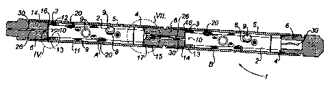
Une structure est réalisée pour le positionnement circonférentiel et longitudinal d'un tube de charge au sein d'un tube porteur, de sorte que les charges du tube de charge soient alignées avec les échancrures du tube porteur. Un collier supérieur, doté d'une clavette externe, est fixé sur la partie supérieure du tube de charge. Une cannelure verticale est usinée à travers les filets supérieurs du tube porteur. Lorsque la clavette pénètre dans la cannelure, le tube porteur est orienté circonférentiellement. De préférence, un disque d'acier à filet extérieur se visse dans les filets inférieurs internes du tube porteur, pour positionner longitudinalement le tube de charge lorsqu'il est introduit dans le tube porteur et se place contre le disque. En outre, le disque supporte et retient le tube chargé dans le tube porteur lorsqu'une section du canon se trouve en position droite, sans bouchon en tandem inférieur pour l'exécution de ces fonctions.


Abrégé anglais

Structure is provided to circumferentially and longitudinally position a charge tube within a carrier tube, so that the charge tube charges are aligned with the carrier tube scallops. A top collar, having an external key, is secured to the top of the charge tube. A vertical groove is machined through the top threads of the carrier tube. When the key enters the groove the carrier tube is circumferentially oriented. Preferably, an externally threaded steel disc is screwed into the internal bottom threads of the carrier tube, to longitudinally position the charge tube when it is inserted into the carrier tube and abuts the disc. The disc further functions to support and retain the charged tube in the carrier tube when a gun section is in an upstanding position without a bottom tandem plug in place to perform these functions.

Revendications

Note : Les revendications sont présentées dans la langue officielle dans laquelle elles ont été soumises.


-9-
Claims:
1. A perforating gun assembly comprising:
a) a charge tube having a plurality of openings that are
spaced longitudinally and circumferentially from one another;
b) a shaped charge fitted into each one of said charge tube
openings;
c) a carrier tube containing said charge tube in concentric
inwardly spaced relationship, said carrier tube having a plurality of scallops
formed in its side wall for registering with the charges;
d) an alignment collar connected to the charge tube, the
collar having a first orienting means and protruding therefrom;
e) a second orienting means positioned on an inner surface
of the carrier tube, wherein the first orienting means and second orienting
means are configured to align the charges with the scallops; and,
f) a longitudinal alignment means positioned in the carrier
tube such that the charge tube is movable within the carrier tube toward the
longitudinal alignment means and when the charge tube bottoms on said
longitudinal alignment means, the charges are longitudinally aligned with the
scallops.
2. The perforating gun assembly as defined in claim 1 wherein
said longitudinal alignment means comprises a member
attached to the inside of the carrier tube.
3. The perforating gun assembly as defined in claim 2 wherein
said member comprises an annular surface for supporting the
charge tube.
4. The perforating gun assembly as defined in claim 2 wherein
said member is detachable from the inside of the carrier tube.
5. The perforating gun assembly as defined in claim 1 wherein

-10-
said longitudinal alignment means comprises an annular
member on which the charge tube bottoms to prevent the charge tube from
dropping out of the carrier tube.
6. A perforating gun assembly comprising:
a) a charge tube having a plurality of openings that are
spaced longitudinally and circumferentially from one another;
b) a shaped charge fitted into each one of said charge tube
openings;
c) a carrier tube containing said charge tube in concentric
inwardly spaced relationship, said carrier tube having a plurality of scallops
formed in its side wall for registering with the charges;
d) a first orienting means protruding from the charge tube;
e) a second orienting means positioned on an inner surface
of the carrier tube, wherein the first orienting means and second orienting
means are configured to align the charges with the scallops; and,
f) a longitudinal alignment member attached to the inside of
the carrier tube;
wherein the charge tube is movable within the carrier tube
toward the annular member such that when the charge tube bottoms on the
annular member, the charges are longitudinally aligned with the scallops.
7. A method for assembling a perforated gun assembly including a
charge tube having a plurality of openings that are spaced longitudinally and
circumferentially from one another, a carrier tube having a plurality of
scallops
formed in its side wall for aligning with the plurality of openings and a
longitudinal alignment means, the method comprising:

-11-
a) fitting a shaped charge into at least one charge tube
opening in the plurality of charge tube openings in the charge tube;
b) providing a first orienting means and a second orienting
means positioned on the charge tube and the carrier tube for circumferentially
aligning the charge tube openings with the scallops;
c) attaching the longitudinal alignment means to a bottom
end of the carrier tube; and,
d) dropping the charge tube into a top end of the carrier tube
such that the first orienting means and the second orienting means cooperate
to circumferentially align the charge tube openings with the scallops, and
when the charge tube bottoms on the longitudinal alignment means, the
charge tube openings are longitudinally aligned with the scallops.
8. The method as defined in claim 7 wherein the second orienting
means is positioned on an inner surface of the carrier tube, and an alignment
collar is connected to the charge tube, the alignment collar having the first
orienting means protruding therefrom, and the method further comprises
inserting the charge tube into the carrier tube such that the first orienting
means and the second orienting means engage, thereby bringing the charge
tube openings into circumferential alignment with the scallops.
9. The method as defined in claim 7 wherein the carrier tube has
lower internal threads at the bottom end, and step c) comprises threading an
externally threaded annular disk into the lower internal threads of the
carrier
tube.
10. A perforating gun assembly for containing shaped charges that
can be detonated to form perforations in a well casing wall, comprising:
a) a charge tube having a plurality of openings that are
spaced longitudinally and circumferentially from one another, at least one of
the plurality of openings being formed to receive a shaped charge;

-12-
b) a carrier tube containing said charge tube in concentric
inwardly spaced relationship, said carrier tube having a plurality of scallops
formed in its side wall for registering with the plurality of openings, the
scallops being weakened wall areas;
c) an alignment collar connected to the charge tube, the
collar having a first orienting means and protruding therefrom;
d) a second orienting means positioned on an inner surface
of the carrier tube, wherein the first orienting means and second orienting
means are configured to align the plurality of openings with the scallops;
and,
e) a longitudinal alignment means positioned in the carrier
tube such that the charge tube is movable within the carrier tube toward the
longitudinal alignment means and when the charge tube bottoms on said
longitudinal alignment means, the plurality of openings are longitudinally
aligned with the scallops.
11. The perforating gun assembly as defined in claim 10 wherein
said longitudinal alignment means comprises a member
attached to the inside of the carrier tube.
12, The perforating gun assembly as defined in claim 11 wherein
said member comprises an annular surface for supporting the
charge tube.
13. The perforating gun assembly as defined in claim 11 wherein
said member is detachable from the inside of the carrier tube.
14. The perforating gun assembly as defined in claim 10 wherein
said longitudinal alignment means comprises an annular
member on which the charge tube bottoms to prevent the charge tube from
dropping out of the carrier tube.

Description

Note : Les descriptions sont présentées dans la langue officielle dans laquelle elles ont été soumises.


CA 02243178 2004-04-02
-2-
Title: CHARGE TUBE RETAINING AND ORIENTING
STRUCTURES FOR A PERFORATING GUN
Field Of The Invention
The invention relates to perforating guns and more particularly
to guns having structures for retaining and orienting the charge tube within
the
carrier tube.
Backctround Of The Invention
Perforating guns are commonly used to bring oil and gas wells
into production. The guns contain shaped charges which can be detonated to
form perforations in the well casing wall.
A perforating gun usually is formed by a string of one or more
sections, each typically comprising:
~ An outer steel tube referred to as the carrier tube. The tube
is relatively thick-walled. It has "scallops" formed in its outer
surface. These are indentations or thinned and weakened
wall areas. These scallops are usually spaced longitudinally
and circumferentially from one another in a spiral pattern;
~ A steel charge tube positioned within the carrier tube in
concentric, inwardly spaced relationship. The charge tube is
relatively thin walled. It has a series of side wall openings
into which the shaped charges are fitted. These openings are
arranged along an identical spiral path so as to coincide or
register with the scallops;
~ The carrier tube is internally threaded at each of its ends so
that externally threaded connection subs may be threaded
thereinto. T he subs function to connect sequential gun
sections together and, at the top section, to connect it to the
tubing string or cable on which it is commonly run;

CA 02243178 2005-03-08
-3-
~ The subs and charge tubes have central connected vertical
passageways through which a detonating cord assembly
extends. At the base of each charge tube and the top of the
adjacent sub, the detonating cord of an upper gun section is
electrically connected with the detonating cord of the next
lower gun section by a pair of boosters separated by a
narrow air gap.
As previously indicated, it is necessary to accurately orient the
charges so that they are in register with or positioned directly opposite to
the
scallops.
Also, when two gun sections are being connected together at
the wellsite, there is a stage where the bottom sub may not form part of one
of
the sections. For example, assume that a gun is being assembled to be run
into the well bore on tubing by a service rig. One section of the gun may be
suspended in the top of the well, with its top sub protruding. The next
section
will only have a sub at its top end, until connected with the section already
in
the well. As a result, the risk exists that the charge tube and its charges
could
slip out the bottom of the carrier tube in the course of raising it vertically
to
connect it with the first section.
So there needs to be some means used to retain the charge
tube within the carrier tube so that it cannot drop out.
In the prior art, these two concerns are dealt with by providing
two collars that attach to the charge tube, one at the base and one at the
top.
The bottom collar is then attached to the carrier tube. More particularly, the
top and bottom collars are attached to the charge tube before it is inserted
into the carrier tube. The top collar is attached by means of screws. One of
the screws is only partially threaded in, so that it protrudes outwardly and
radially. When the charge tube is inserted into the carrier tube, the
protruding
screw engages a vertical groove formed by the interior surface of the carrier
tube, thereby ensuring correct circumferential orientation. The bottom collar
attaches to the bottom of the charge tube with screws as well. Once the

CA 02243178 2004-04-02
-4-
charge tube is inserted into the carrier tube, the bottom collar must then be
secured to the carrier tube by means of screws, so that the charge tube does
not drop through the bottom of the carrier tube. However this is awkward to
do.
It is therefore one object of the invention to provide an improved
system for orienting the charge tube so that its charges are circumferentially
aligned with the scallops.
In accordance with an embodiment of the invention, it is another
object to provide a means for simultaneously retaining the charge tube in the
carrier tube, when no bottom sub is in place, and for positioning the charge
tube so thafi its charges are longitudinally aligned with the scallops.
Summary Of The Invention
In a preferred form of the invention, two modifications are made
to the conventional perforating gun. More particularly:
~ A top collar having an external vertical key and three screw
holes is provided. The key and holes are equidistantly
located around the collar. The charge tube will have been
provided with three holes corresponding with the collar holes.
A vertical groove is formed in the side wall of the carrier tube,
through the upper internal threads so as to extend below the
threads. Screws are inserted through the collar holes to
penetrate the charge tube holes. This fixes the location of the
key. The locations of the screw holes, key and groove have
been coordinated and arranged so that the charges are
automatically circumferentially aligned with the scallops
when the key is dropped into the groove;
~ Preferably, an annular steel disc having external threads is
also provided. The disc is screwed up to the top of the lower
threads of the carrier tube. It functions to support the charge
tube at its bottom end. The location of the thread end is

CA 02243178 2004-04-02
-5-
coordinated and arranged so that the charges are
automatically longitudinally aligned with the scallops. When
the bottom sub is threaded in, it serves to support the disc in
retaining the charge tube.
Most preferably, the disc has a relatively thick outer annular
portion (to enable threads to be cut in its circumferential surface) and a
relatively thin inner portion (to minimize the air gap between the bottom
booster of the top gun section and the top booster of the bottom gun section).
As a result of the foregoing, a perforating gun assembly is
provided which can more easily be assembled. There is automatic orientation
and positioning of the charges opposite the scallops. And the charge tube is
prevented from dropping out of the carrier tube when the bottom sub is not in
place.
In accordance with an embodiment of the invention, there is
provided a perforating gun assembly comprising: a charge tube carrying a
plurality of charges that are spaced longitudinally and circumferentially from
one another; a carrier tube having upper and lower internal threads at its
upper and lower ends, said carrier tube containing the charge tube in
concentric, inwardly spaced relationship, said carrier tube having scallops
formed in its side wall, for registering with the charges; an annular
alignment
collar secured to the top of the charge tube; the collar having first
orienting
means formed by its outer surface; the carrier tube having second orienting
means formed by its inner surface; said first and second orienting means
being engaged and causing the carrier tube to be positioned with its charges
aligned circumferentially with the scallops; an externally threaded, annular
disc, positioned at the upper end of the carrier tube's lower threads, said
disc
supporting the charge tub S.~. that W charges arc aligned i~ngitudiiW lly
v~iiih
the scallops, said disc preventing the charge tube from dropping out of the
carrier tube; whereby the charge tube is retained in the carrier tube with the
scallops in register with the charges.

CA 02243178 2004-04-02
-6-
Description Of The Drawincts
Figure 1 is a cross-sectional side view of an assembled
perforating gun having two sections in accordance with an embodiment of the
invention;
Figure 2 is a sectional plan view of the upper alignment collar;
Figure 3 is a perspective view of the collar of Figure 2;
Figure 4 is an expanded cross-sectional side view of the collar
structure shown in circle IV of Figure 1;
Figure 5 is a perspective view of the retainer disc;
Figure 6 is a cross-sectional side view of the retainer disc;
Figure 7 is an expanded cross-sectional side view of the disc in
the gun, shown in circle VII of Figure 1;
Figure 8 is a perspective view of the upper end of the carrier
tube with part of the side wall broken away, showing an orienting groove
extending down into the unthreaded portion of the side wall; and
Figure 9 is a sectional side view showing a tandem sub
connecting two gun sections.
Description Of The Preferred Embodiment
An embodiment of the invention will first be described in
connection with the fully assembled perforating gun assembly 1 shown in
Figure 1.
The assembly 1 comprises two sections A, B, each comprising a
charge tube 2, an upper alignment collar 3, a charge tube retainer disc 4, a
carrier tube 5 and connecting subs 6.
Each charge tube 2 has a series of charge openings 8 spaced
circumferentially and longitudinally relative to one another. A shaped charge
9
is fitted into the uppermost opening 8. Usually there will be a plurality of
charges mounted in the charge tube.

CA 02243178 2004-04-02
_7_
At its upper end, three openings 10 are formed in the side wall
11 of the charge tube 2. The openings 10 are spaced apart equidistantly at
1/4, 1/2 and 3/4 of the circumferential extent.
The collar 3 is mounted on the end of the charge tube 2. The
collar 3 is annular in configuration and has an outwardly protruding key 12
and three side openings 13. The key 12 and openings 13 are equidistantly
spaced around the collar 3. It also has an internal upper lip 19 for
positioning
the openings 13 at the desired elevation on the charge tube 2.
The carrier tube 5 is internally threaded at its upper and lower
ends. The upper and lower threads 14, 15 terminate at 16, 17 respectively. A
vertical groove 18 extends down through the threads 14 into the non-threaded
side wall 11, as shown in Figure 8.
The carrier tube 5 has a series of scallops 20 formed in its side
wall 21. The scallops 20 are areas where the side wall 21 is weakened by
thinning it. The scallops 20 are spirally arranged so that they are
circumferentially and longitudinally spaced one from another.
In assembling the assembly 1, the collar 3 is seated on the
upper end of the charge tube 2. The collar side openings 13 are aligned with
the charge tube openings 10. Screws 23 are screwed into the aligned
openings 13, 10 to fix the collar 2 on the charge tube 2.
An annular, externally threaded steel disc 4 is screwed into the
carrier tube 5 from its bottom end. When the disc 4 reaches the top 17 of the
lower threads 15, it is in position to control the longitudinal location of
the
charge tube 2.
When the charge tube 2 is dropped into the carrier tube 5,
engagement of the key 17 and grnn.~o 1~ r..-~o.,+ +t". ~. g ~~~ ~~ wit h i h8
_.. .. . r ~ .,... .. ~ v. ici mS a is i.v iar a a
scallops 20 with respect to circumferential location. Simultaneously, the
charge tube 2 bottoms on the disc 4, which fixes the longitudinal positioning
of
the charges 9. In this way, the charges 9 are located opposite to the scallops
20.

CA 02243178 2004-04-02
_ 8
As shown in Figures 5-7, the disc 4 is constructed with a thinned
inner portion 4a and a thickened outer portion 4b. The thickened outer portion
4b provides strength and enables cutting of the threads 25 in the
circumferential edge surface of the disc 4. The purpose of thinning the
portion
4a is explained below.
As shown in Figures 1 and 9, the connecting subs 6 have axial
passageways or bores 26 through which detonator cords 30a, 30b extend. At
the bottom end of the top charge tube 2 an internal insert 31 is positioned.
Insert 31 is connected with detonator cord 30a. At the top end of sub bore 26,
a second insert 32 is positioned. The two inserts 31, 32 each comprise
boosters 33, 34 for transmitting energy from the upper gun section A to the
lower gun section B through an air gap 35. The disc 4 is thinned to minimize
the air gap 35.
In summary then, the embodiment of the invention described
above provides means which facilitate the assembling of the gun sections and
ensure retention of the charge tube when the bottom sub 6 is not in the
assembly.
The scope of the invention is defined by the claims now
following.

Dessin représentatif
Une figure unique qui représente un dessin illustrant l'invention.
États administratifs

2024-08-01 : Dans le cadre de la transition vers les Brevets de nouvelle génération (BNG), la base de données sur les brevets canadiens (BDBC) contient désormais un Historique d'événement plus détaillé, qui reproduit le Journal des événements de notre nouvelle solution interne.

Veuillez noter que les événements débutant par « Inactive : » se réfèrent à des événements qui ne sont plus utilisés dans notre nouvelle solution interne.

Pour une meilleure compréhension de l'état de la demande ou brevet qui figure sur cette page, la rubrique Mise en garde , et les descriptions de Brevet , Historique d'événement , Taxes périodiques et Historique des paiements devraient être consultées.

Historique d'événement

Description Date
Le délai pour l'annulation est expiré 2018-07-16
Lettre envoyée 2017-07-14
Inactive : Lettre officielle 2007-01-19
Inactive : Paiement correctif - art.78.6 Loi 2007-01-04
Inactive : Brevet abandonné 2006-04-04
Exigences de redélivrance - jugée conforme 2006-04-04
Lettre envoyée 2006-04-04
Inactive : Correction - Doc. d'antériorité 2006-04-03
Inactive : CIB de MCD 2006-03-12
Inactive : Page couverture publiée 2006-03-03
Demande visant une demande de redélivrance reçue 2006-02-20
Demande visant une demande de redélivrance reçue 2006-02-14
Inactive : Lettre officielle 2005-12-28
Inactive : Supprimer l'abandon 2005-12-01
Inactive : Demande ad hoc documentée 2005-12-01
Inactive : Abandon. - Aucune rép. à lettre officielle 2005-10-14
Modification reçue - modification volontaire 2005-09-02
Inactive : Demande ad hoc documentée 2005-08-24
Lettre envoyée 2005-07-28
Exigences de prorogation de délai pour l'accomplissement d'un acte - jugée conforme 2005-07-28
Demande de prorogation de délai pour l'accomplissement d'un acte reçue 2005-07-13
Inactive : Prorogation de délai lié aux transferts 2005-07-13
Inactive : Lettre officielle 2005-04-14
Modification reçue - modification volontaire 2005-03-08
Exigences de prorogation de délai pour l'accomplissement d'un acte - jugée conforme 2004-12-21
Lettre envoyée 2004-12-21
Demande de prorogation de délai pour l'accomplissement d'un acte reçue 2004-12-08
Inactive : Lettre officielle 2004-09-08
Lettre envoyée 2004-04-22
Exigences relatives à la révocation de la nomination d'un agent - jugée conforme 2004-04-21
Inactive : Lettre officielle 2004-04-21
Exigences relatives à la nomination d'un agent - jugée conforme 2004-04-21
Demande visant une demande de redélivrance reçue 2004-04-02
Inactive : Taxe de redélivrance traitée 2004-04-02
Accordé par délivrance 2002-06-11
Inactive : Page couverture publiée 2002-06-10
Préoctroi 2002-03-27
Inactive : Taxe finale reçue 2002-03-27
Lettre envoyée 2001-12-07
Inactive : Transfert individuel 2001-10-29
Un avis d'acceptation est envoyé 2001-10-11
Lettre envoyée 2001-10-11
Un avis d'acceptation est envoyé 2001-10-11
Inactive : Approuvée aux fins d'acceptation (AFA) 2001-09-28
Inactive : Demande ad hoc documentée 2001-08-16
Lettre envoyée 2001-08-16
Avancement de l'examen jugé conforme - alinéa 84(1)a) des Règles sur les brevets 2001-08-16
Inactive : Grandeur de l'entité changée 2001-08-16
Exigences relatives à la révocation de la nomination d'un agent - jugée conforme 2001-08-01
Inactive : Lettre officielle 2001-08-01
Exigences relatives à la nomination d'un agent - jugée conforme 2001-08-01
Toutes les exigences pour l'examen - jugée conforme 2001-06-28
Exigences pour une requête d'examen - jugée conforme 2001-06-28
Inactive : Taxe de devanc. d'examen (OS) traitée 2001-06-28
Inactive : Avancement d'examen (OS) 2001-06-28
Requête d'examen reçue 2001-06-28
Demande visant la nomination d'un agent 2001-06-12
Demande visant la révocation de la nomination d'un agent 2001-06-12
Lettre envoyée 2000-05-04
Inactive : Transfert individuel 2000-04-07
Demande publiée (accessible au public) 2000-01-14
Inactive : Page couverture publiée 2000-01-13
Inactive : CIB en 1re position 1998-10-30
Symbole de classement modifié 1998-10-30
Inactive : CIB attribuée 1998-10-30
Inactive : Certificat de dépôt - Sans RE (Anglais) 1998-09-18
Exigences de dépôt - jugé conforme 1998-09-18
Demande reçue - nationale ordinaire 1998-09-17

Historique d'abandonnement

Il n'y a pas d'historique d'abandonnement

Taxes périodiques

Le dernier paiement a été reçu le 2001-06-28

Avis : Si le paiement en totalité n'a pas été reçu au plus tard à la date indiquée, une taxe supplémentaire peut être imposée, soit une des taxes suivantes :

  • taxe de rétablissement ;
  • taxe pour paiement en souffrance ; ou
  • taxe additionnelle pour le renversement d'une péremption réputée.

Les taxes sur les brevets sont ajustées au 1er janvier de chaque année. Les montants ci-dessus sont les montants actuels s'ils sont reçus au plus tard le 31 décembre de l'année en cours.
Veuillez vous référer à la page web des taxes sur les brevets de l'OPIC pour voir tous les montants actuels des taxes.

Titulaires au dossier

Les titulaires actuels et antérieures au dossier sont affichés en ordre alphabétique.

Titulaires actuels au dossier
CORE LABORATORIES CANADA LTD.
Titulaires antérieures au dossier
ANDREW BUZINSKY
Les propriétaires antérieurs qui ne figurent pas dans la liste des « Propriétaires au dossier » apparaîtront dans d'autres documents au dossier.
Documents

Pour visionner les fichiers sélectionnés, entrer le code reCAPTCHA :


Pour visualiser une image, cliquer sur un lien dans la colonne description du document. Pour télécharger l'image (les images), cliquer l'une ou plusieurs cases à cocher dans la première colonne et ensuite cliquer sur le bouton "Télécharger sélection en format PDF (archive Zip)" ou le bouton "Télécharger sélection (en un fichier PDF fusionné)".

Liste des documents de brevet publiés et non publiés sur la BDBC .

Si vous avez des difficultés à accéder au contenu, veuillez communiquer avec le Centre de services à la clientèle au 1-866-997-1936, ou envoyer un courriel au Centre de service à la clientèle de l'OPIC.


Description du
Document 
Date
(aaaa-mm-jj) 
Nombre de pages   Taille de l'image (Ko) 
Abrégé 1998-07-13 1 24
Description 1998-07-13 9 299
Revendications 1998-07-13 2 51
Dessins 1998-07-13 5 197
Dessin représentatif 2000-01-04 1 13
Dessin représentatif 2002-05-06 1 13
Abrégé 2004-04-01 1 21
Description 2004-04-01 7 282
Revendications 2004-04-01 3 90
Dessins 2005-03-07 5 192
Description 2005-03-07 7 281
Revendications 2005-03-07 3 102
Revendications 2005-09-01 3 108
Dessin représentatif 2006-03-02 1 14
Revendications 2006-02-19 4 161
Certificat de dépôt (anglais) 1998-09-17 1 174
Rappel de taxe de maintien due 2000-03-14 1 111
Courtoisie - Certificat d'enregistrement (document(s) connexe(s)) 2000-05-03 1 113
Avis du commissaire - Demande jugée acceptable 2001-10-10 1 166
Courtoisie - Certificat d'enregistrement (document(s) connexe(s)) 2001-12-06 1 113
Avis concernant la taxe de maintien 2017-08-24 1 182
Avis concernant la taxe de maintien 2017-08-24 1 181
Taxes 2001-06-27 1 30
Taxes 2002-07-02 1 37
Correspondance 2001-07-31 1 14
Correspondance 2001-07-31 1 16
Correspondance 2002-03-26 1 30
Taxes 2000-06-12 3 103
Correspondance 2004-04-20 1 15
Correspondance 2004-04-20 1 13
Correspondance 2004-04-21 1 13
Correspondance 2004-12-07 1 37
Correspondance 2004-12-20 3 108
Correspondance 2005-07-27 1 14
Correspondance 2005-07-12 1 34
Correspondance 2005-12-27 1 14
Correspondance 2006-04-03 1 15
Taxes 2006-07-06 1 31
Correspondance 2007-01-18 1 12