Note : Les descriptions sont présentées dans la langue officielle dans laquelle elles ont été soumises.
CA 02244468 1998-08-04
-2-
GAS-FIRED WATER HEATER HAVING PLATE-MOUNTED
REMOVABLE BOTTOM END BURNER AND PILOT ASSEMBLY
BACKGROUND OF THE INVENTION
The present invention generally relates to fuel-fired water heaters and,
in a preferred embodiment thereof, more particularly provides a gas-fired
water
heater having incorporated therein a specially designed plate-mounted
removable bottom end burner and pilot assembly circumscribed by a flame
arresting combustion air intake structure.
Gas-fired residential and commercial water heaters are generally formed
to include a vertical cylindrical water storage tank with a gas burner
disposed
in a combustion chamber below the tank. The burner is supplied with a fuel
gas through a gas supply line, and combustion air through one or more air
inlet
openings providing communication between ambient air and the interior of the
combustion chamber.
Water heaters of this general type are extremely safe in operation.
However, when gasoline or other flammable liquids are stored or used
improperly in proximity to the water heater, there may exist a possibility of
flammable vapors becoming entrained in the air intake of the water heater. It
is theorized that such vapors might cause secondary combustion to occur
within the confines of the water heater combustion chamber. It is accordingly
possible for the resulting flame to propagate out of the combustion chamber
into the ambient environment around the water heater as a result of following
the intake path of the flammable vapor.
In conventionally constructed water heaters of this general type, a
combustion chamber access door is typically provided in a vertical side wall
CA 02244468 1998-08-04
-3-
portion of the water heater, with the burner and pilot gas supply lines
extending horizontally through the access door into the combustion chamber
and connected to their associated burner and pilot structures within the
combustion chamber. This access door design can possibly provide a potential
leakage path between the combustion chamber and the exterior of the water
heater. Another potential leakage path is presented by the inlet passage used
to flow ambient combustion air into the combustion chamber. For water
heater designs focusing on controlling the entrance location of flammable
vapors passing into the combustion chamber it would be desirable to provide
a sealed access structure for the combustion chamber and to hinder the
entrance of flammable vapors into the combustion chamber via an unintended
combustion air inflow path. It is to these goals which the present invention
is
directed.
SUMMARY OF THE INVENTION
In carrying out principles of the present invention, in accordance with a
preferred embodiment thereof, an improved fuel-fired water heater is provided.
The water heater is representatively a gas-fired water heater, but could
alternatively be an oil-fired water heater, and includes a tank adapted to
hold
a quantity of water, and a combustion chamber disposed beneath the tank and
having a bottom side wall structure with a burner mounting opening extending
upwardly therethrough.
A mounting plate structure is secured to the underside of the bottom
side wall structure, over the burner mounting opening, and is downwardly
removable from the bottom side wall structure. Secured to the top side of the
CA 02244468 1998-08-04
-4-
mounting plate structure for downward removal therewith from the bottom
side plate structure is a fuel burner which projects upwardly into the
combustion chamber through the burner mounting opening in the bottom side
wall structure. The burner is operatively connected to a fuel supply pipe that
is disposed externally of the combustion chamber and is removably coupled to
a fuel valve device, representatively a thermostatic gas valve, externally
mounted on the water heater. A single seal element, illustratively an annular
high temperature sealing gasket, is used to seal the mounting plate structure
to the underside of the bottom side wall structure.
According to a feature of the present invention, it is necessary to
decouple the fuel supply pipe from the fuel valve device to remove the
mounting plate structure from the bottom side wall structure and thereby
uncover the burner mounting opening. Thus, the burner mounting opening
cannot be uncovered while the burner is firing. Additionally, when the
mounting plate structure is replaced, its operative re-sealing to the bottom
side
wall structure of the combustion chamber can be more easily and reliably
achieved using the single seal element interposed between the mounting plate
structure and the bottom side wall structure.
An air inlet path is provided through which combustion air may be
flowed into the interior of the otherwise sealed combustion chamber, a portion
of this air inlet path being defined by a spaced series of openings formed in
the
bottom side wall structure, and preferably in the mounting plate structure as
well. According to another aspect of the present invention, these openings act
as flame arrestors to inhibit flame outflow therethrough from within the
combustion chamber as might possibly occur in the event that flammable
CA 02244468 1998-08-04
-5-
vapors passing upwardly through the openings were to be ignited within the
combustion chamber during operation of the water heater.
The combustion air inlet openings disposed on the bottom side of the
combustion chamber are sized and configured to ( 1 ) freely permit upward
combustion air flow therethrough into the combustion chamber, and at the
same time (2) hinder flame outflow downwardly through the combustion air
inlet openings. Preferably, these openings have predetermined hydraulic
diameter characteristics causing them to quench a flame passing downwardly
therethrough.
Illustratively, the bottom side wall structure and the mounting plate
structure are each of a steel construction and are approximately 0.25 inches
thick, each of the spaced series of combustion air inlet openings has a
generally circular cross-section with a diameter of approximately 0.063
inches,
and the openings have a center-to-center spacing of approximately 0.125
inches. Preferably, the bottom side wall structure and the mounting plate
structure are each formed from a plurality of stacked perforated steel plates
(representatively four in number) in which the perforations therein are in
registry with one another to combinatively form the combustion air inlet
openings. Alternatively, each of the bottom side wall structure and the
mounting plate structure could be of a one piece metal construction, and the
combustion air inlet openings could be formed only in the bottom side wall
structure.
In a preferred embodiment thereof, the water heater further includes a
hollow skirt structure extending downwardly beyond the bottom side wall
structure and having a vertical side wall portion with a spaced series of
inlet
CA 02244468 1999-12-21
-6-
openings formed therein for permitting a combustion air inflow therethrough
into the interior of the hollow skirt structure for delivery therefrom into
the
combustion chamber via the combustion air inlet openings in the bottom side
of the combustion chamber.
Additionally, in the preferred water heater embodiment an insulating
jacket structure circumscribes the tank. The insulating jacket structure has
an
outer wall portion with a lower end section that outwardly circumscribes the
hollow skirt structure and defines therewith an air inlet plenum. The lower
end
section of this outer jacket wall portion has a spaced series of air inlet
openings
therein that permit combustion air to flow inwardly therethrough into the air
inlet plenum for delivery therefrom into the interior of the hollow skirt
structure
through the inlet openings in its vertical side wall portion.
The vertical side wall portion of the skirt structure and the outer jacket
wall portion preferably have aligned access openings formed therein through
which a horizontal portion of the fuel supply pipe outwardly passes before
turning upwardly to its coupling location on the thermostatic fuel valve. The
mounting plate structure, the fuel burner, and a portion of the fuel supply
pipe
are outwardly removable through the access openings when the fuel supply
pipe is decoupled from the thermostatic fuel valve and the mounting plate
structure is downwardly removed from the bottom side wall structure of the
combustion chamber. A suitable removable cover plate is externally attached
to the water heater to cover the access openings until removal of the fuel
burner is desired.
CA 02244468 1998-08-04
_7_
BRIEF DESCRIPTION OF THE DRAWINGS
FIG. 1 is a simplified partial cross-sectional view through a gas-fired
water heater embodying principles of the present invention and having a
removable bottom end-mounted burner and pilot assembly circumscribed by a
flame outflow-arresting air inlet structure;
FIG. 1 A is a view similar to that in FIG. 1, but with the burner and pilot
assembly downwardly removed from the lower end of the water heater;
FIG. 2 is an enlarged detail view of the dashed circle area "2" in FIG. 1;
FIG. 3 is an enlarged detail view of the dashed circle area "3" in FIG. 1;
FIG. 3A is a view similar to that in FIG. 3, but showing an alternate
construction of a plate structure upon which the burner and pilot assembly is
mounted; and
FIG. 4 is a side elevational view of the water heater taken along line 4-4
of FIG. 1.
DETAILED DESCRIPTION
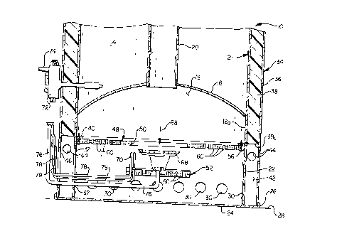
Cross-sectionally illustrated in simplified form in FIG. 1 is a lower end
portion of a specially designed fuel-fired water heater 10 embodying
principles
of the present invention. Illustratively, the fuel-fired water heater 10 is a
gas-
fired water heater, utilizing natural or liquified petroleum gas, but could
alternatively be an oil-fired water heater. Water heater 10 has a vertically
oriented cylindrical metal water storage tank 12 in which a quantity of heated
water 14 is stored, the tank 12 having an upwardly domed bottom head
portion 16 that defines the upper wall of a combustion chamber 18 which
communicates with the open lower end of a combustion flue tube 20 that
CA 02244468 1998-08-04
_8_
centrally extends upwardly through the interior of the tank 12. An annular
outer side wall portion of the combustion chamber 18 is defined by an annular
lower end portion 12a of the tank which extends downwardly past the
periphery of the bottom head portion 16. In a conventional manner suitable
outlet and inlet pipes (not shown) are connected to the tank 12 to
respectively
flow heated water out of the tank and flow water to be heated into the tank.
The lower end portion 12a of the tank 12 is supported atop an annular
skirt structure 22 having an open lower end 24 which is received in a bottom
pan member 26 that rests on a suitable horizontal support surface such as the
indicated floor 28. A circumferentially spaced array of combustion air inlet
openings 30 are formed in the vertical side wall portion of the skirt
structure
22 near the bottom end 24 of the skirt, and an access opening 32 is formed
in the skirt 22 in a left portion thereof as viewed in FIG. 1.
Outwardly circumscribing the tank 12 is a cylindrical insulating jacket
structure 34 having an annular outer metal jacket portion 36 which is coaxial
with the tank 12 and spaced outwardly therefrom. A suitable insulation
material, such as foam insulation 38, is disposed within the annular space
between the metal jacket portion 36 and the tank 12. The lower end of the
metal jacket portion 36 is received within the bottom pan 26, and the
insulation 38 has an annular lower end surface 38a which is spaced upwardly
apart from the lower end of the jacket portion 36 and is vertically adjacent
an
annular, inturned flange 40 formed on the upper end of the skirt 22 (see FIG.
2).
The absence of insulation 38 vertically along the skirt 22 forms an
annular air intake plenum space 42 between the skirt 22 and a lower end
CA 02244468 1998-08-04
_g_
section of the jacket portion 36. At the upper end of the plenum 42 a
circumferentially spaced series of air inlet openings 44 are formed in the
jacket
portion 36. Additionally, an access opening 46 is formed in a left side of the
skirt 22 (as viewed in FIG. 1 ) and is aligned with the access opening 32
formed in a left side portion of the skirt 22.
The bottom side wall of the combustion chamber 18 is positioned at the
top side of the skirt structure and is defined by ( 1 ) an annular, perforated
bottom side wall structure 48 having a central circular burner mounting hole
50, and (2) a circular perforated mounting plate structure 52. As best
illustrated in FIG. 2, the bottom side wall structure 48 is positioned beneath
the skirt flange 40, with an annular high temperature sealing gasket 54 being
interposed between a peripheral edge portion of the bottom side wall structure
48 and the skirt flange 40. This peripheral edge portion of the bottom side
wall structure 48 is sealed to the underside of the flange 40 by a
circumferentially spaced series of screws 56 extending upwardly through the
periphery of the bottom side wall structure 48, and the flange 40, and
compressing the gasket 54.
Preferably, the bottom side wall structure 48 is formed from a stacked
plurality of annular perforated metal plates 58 (representatively four in
number), with the perforations in the plates 58 being in registry with one
another to combinatively define a spaced series of vertical combustion air
intake openings 60 vertically extending from the bottom side of the bottom
side wall structure 48 to its top side. The illustrated openings 60 have
circular
cross-sections along their lengths, but could alternatively have other cross-
sectional configurations. While the bottom side wall structure 48 is
CA 02244468 1998-08-04
-10-
illustratively formed from a stacked plurality of perforated plates, it will
be
appreciated that if desired it could be alternatively formed from a single
thicker
plate.
The mounting plate structure 52 extends along a central lower side
portion of the bottom side wall structure 48 and covers the burner mounting
hole 50 therein (see FIGS. 1 and 3). A high temperature sealing gasket 62 is
interposed between facing peripheral portions of the mounting plate structure
52 and the burner mounting opening 50, with a circumferentially spaced series
of screws 64 extending upwardly through the overlapping peripheral portions
of the bottom side wall structure 48 and the mounting plate structure 52 and
compressing the gasket 62 to form a peripheral seal between the bottom side
wall structure 48 and the mounting plate structure 52.
Like the annular bottom side wall structure 48, the circular mounting
plate structure 52 is formed from a stacked plurality of perforated plates 66
(representatively four in number) whose individual perforations are in
registry
with one another to combinatively form in the mounting plate structure 52 a
spaced series of combustion air intake openings 60 that vertically extend from
the bottom side of the mounting plate structure 52 to its top side.
Alternatively, the perforated mounting plate structure could be formed from a
single, thicker metal plate with the openings 60 formed therethrough, or be an
unperforated mounting plate structure 52a as shown in FIG. 3A.
A gas burner 68 and an associated pilot and thermocouple assembly 70
are suitably secured to and project upwardly from the top side of the mounting
plate structure 52 into the combustion chamber 18. To provide external
visibility of the burner flame within the combustion chamber, a suitable sight
CA 02244468 1998-08-04
-11-
glass structure of conventional construction (not shown) is provided on the
water heater. A thermostatic gas supply valve 72, which monitors the
temperature of the stored water 14 and correspondingly controls the firing of
the burner 68, to maintain a predetermined tank water temperature, is
externally mounted on the outer side of the jacket structure 34 on the left
side
of the water heater 10 as viewed in FIG. 1.
Thermostatic valve 72 receives a supply of gaseous fuel through a gas
pipe 74 and is operatively coupled to ( 1 ) the burner 68 by a gas supply pipe
76, and (2) the pilot/thermocouple assembly 70 by a pilot gas line 78, the
body
79 of the thermocouple portion of the assembly 70, and electrical wiring (not
shown). Gas lines 76 and 78, the thermocouple body 79, and the electrical
wiring sequentially extend downwardly from the gas valve 72 externally of the
jacket structure 34, pass inwardly into the interior of the skirt 22 via the
jacket
and skirt access openings 46 and 32, and then extend upwardly through the
mounting plate structure to connect to the burner 68 and the
pilot/thermocouple assembly 70. In this manner, the piping and wiring are
advantageously kept out of the interior of the hot combustion chamber 18.
As best illustrated in FIG. 4, a notched cover plate 80 is removably
secured to the outer side of the jacket structure 34 over the jacket access
opening 46 by means of flanges 82 formed on top side portions of the cover
plate and removably interlocked with corresponding flanges formed on the
outer metal jacket portion 36. For purposes later described herein, bottom
side
portions of the aligned access openings 46,32 (se FIG. 4) are notched as at
84.
CA 02244468 1998-08-04
-12-
As illustrated in FIG. 1, during operation of the water heater 10, while
the burner 68 is firing, ambient combustion air 86 exteriorly adjacent the
water
heater 10 is sequentially drawn inwardly through the jacket openings 44,
downwardly through the skirt/jacket plenum area 42, inwardly through the skirt
wall openings 30 into the interior of the skirt 22, and upwardly into the
combustion chamber 18 via the openings 60 in the bottom side wall structure
48 and the mounting plate structure 52. The air 86 entering the combustion
chamber 18 mixes and is combusted with fuel exiting the burner 68. The
resulting hot combustion gases flow upwardly through the flue tube 20 and are
used to supply heat to the tank water 14.
When it becomes necessary to inspect, service or replace the burner 68
and/or the pilot/thermocouple assembly 70, the cover plate 80 (see FIG. 4) is
removed and the pipes 76 and 78, the thermocouple body 79, and the
associated electrical wiring (not shown) are decoupled from the thermostatic
gas valve 72. Additionally, via the jacket and skirt access openings 46 and 32
the screws 64 (see FIG. 1 ) are removed from the mounting plate structure 52.
Then, as indicated by the arrow 88 in FIG. 1 A, the mounting plate structure
52
is downwardly removed from the bottom side of the bottom side wall structure
48, thereby lowering the mounting plate structure 52, the burner 68, the
pilot/thermocouple structure 70 and the associated piping 76,78 and
thermocouple body 79 to their FIG. 1 A positions. The aligned access openings
46,32 are configured to permit the downward movement of the horizontal
portion of the gas supply pipe 76, with the bottom side notches 84 of such
access openings receiving a horizontal portion of the pipe 76. The removed
CA 02244468 1998-08-04
-13-
mounting plate, burner, pilot/thermocouple assembly and relating piping
structures may be pulled leftwardly out of the aligned access openings 46,32.
By mounting the burner 68 and the pilot/thermocouple assembly 70 on
the bottom side wall structure 48 of the combustion chamber 18 using the
mounting plate structure 52, several advantages are gained over conventional
water heater design in which access to the combustion chamber is provided
by an access door which is mounted on a vertical side wall portion of the
combustion chamber.
First, these conventional vertically oriented access door structures are
typically formed from several pieces, at least one of which is provided with
openings for the main burner and pilot gas piping to pass through into a
horizontally central portion of the combustion chamber. This access door
placement and construction necessitates the use of several seal elements
which must be carefully installed when the water heater is manufactured, and
then carefully replaced after subsequently servicing the burner and pilot
structures. By using the bottom mounted cover plate structure 52 of the
present invention, however, only a single seal (representatively, the gasket
member 62 shown in FIGS. 3 and 3A) is required. This makes it considerably
easier to assure that a good seal is maintained at the combustion chamber
opening 50.
Second, conventionally configured, vertically oriented combustion
chamber access doors are typically openable during firing of the burner within
the combustion chamber, thereby communicating the burner flame with the
ambient environment exterior to the water heater. In the present invention,
however, this condition cannot occur since to uncover the combustion
CA 02244468 1998-08-04
-14-
chamber bottom side wall opening 50 it is necessary to decouple the gas
piping from the thermostatic gas valve 72, thereby positively precluding the
presence of a flame within the combustion chamber when the opening 50 is
uncovered.
Third, as can be seen in FIG. 1, in the present invention the gas piping
76,78 is disposed entirely externally of the combustion chamber 18 - no
portion of such piping need be run through the hot interior of the combustion
chamber. Additionally, the horizontal run of the piping 76,78 is desirably
supported by the mounting plate structure 52 such that neither the burner 68
nor the pilot/thermocouple assembly 70 exert a cantilever load on such piping.
The combustion chamber 18 is generally sealed except at the
combustion air intake openings 60 in the bottom side wall structure 48 and the
mounting plate structure 52 (or only in the bottom side wall structure 48 in
the
embodiment shown in FIG. 3A). Thus, the openings 60 define essentially the
sole passage through which the combustion air 86 may enter the interior of the
combustion chamber 18. According to another key feature of the present
invention, the spacing and configurations of the openings 60 are selected to
cause the openings 60 to ( 1 ) allow the combustion air 86 to flow upwardly
through the openings 60 with a pressure drop which is sufficiently low so as
to not materially impede the normal combustion process of the fuel-fired water
10, while at the same time (2) act as flame arresting passages that hinder a
downward flow of flames through the openings 60 in the event that flammable
vapors passing upwardly through the openings 60 are ignited within the
combustion chamber 18.
CA 02244468 1998-08-04
-15-
To provide the combustion air inlet openings 60 with these two
characteristics, their hydraulic or effective diameters and their passage
lengths
are selected in a manner such that upward air inlet flow through the openings
60 can occur with minimal pressure drop, but the openings 60 act to decrease
downward flame propagation velocity therethrough in a manner extracting
sufficient heat from such downwardly directed flames to quench them before
they downwardly exit the openings 60. In this manner, downward flame
outflow through the bottom ends of the openings 60, caused by ignition within
the combustion chamber 18 of flammable vapors upwardly entering the
combustion chamber through the openings 60, is hindered to thereby reduce
the possibility of such ignition being spread to flammable vapors externally
adjacent the combustion chamber 18.
There are two primary flame control situations which should be
considered in the context of water heater design. The first concerns high
velocity flame (i.e., a flame having a propagation velocity greater than about
50 feet per secondl. To arrest a high velocity flame, the flame must be both
decelerated and quenched. The second situation concerns low velocity flame
(i.e., a flame having a propagation velocity less than about 50 feet per
second)
in which case flame quenching is usually sufficient to arrest the flame.
Whether or not a flame is quenched before it exits a passage through
which it is traveling depends on several factors such as the passageway
length, the effective or hydraulic diameter of the passageway, the approach
velocity of the flame, the pressure differential between the inlet and outlet
of
the passageway, and the temperature of the material in which the passageway
is formed. In turn, the flame approach velocity for a given fuel depends on
the
CA 02244468 1998-08-04
-16-
fuel and air mixture ration. Maximum flame velocity occurs at a stoichiometric
fuel/air ratio, while minimum velocity tends to occur at a lean fuel/air
ration.
In general, as flame speed is increased the hydraulic diameter should be
decreased and the passageway length increased.
In the depicted preferred embodiment of the present invention, the four
stacked metal plates 58 in the combustion chamber bottom side wall structure
48 (and the four stacked metal plates 66 in the mounting plate structure 52
shown in FIG. 3) each have a thickness of approximately 0.063 inches.
Accordingly, the total thickness of the each of the bottom side wall structure
48 and the mounting plate structure is approximately 0.25 inches. Thus, if
each of these two structures is formed from a single layer of metal
(preferably
steel) the single metal layer would similarly have a thickness of
approximately
0.25 inches.
Preferably, the diameter of each of the openings 60 is approximately
0.063 inches, and the center-to-center spacing of the openings 60 is
approximately 0.125 inches. As previously mentioned, the openings 60 have
circular cross-sections but could be provided with noncircular cross-sections,
having equivalent hydraulic diameters, if desired.
In developing the water heater 10 of the present invention it has been
found that the use of the specially configured combustion air inlet openings
60
at the bottom side of the combustion chamber 18 serves to quench low
velocity flames, and quench and decelerate high velocity flames, in a manner
hindering their downward outflow through the openings 60. While these flame
backflow-arresting opening have been illustratively shown as being disposed
along the bottom side of the combustion chamber 18, it will be appreciated by
CA 02244468 1998-08-04
-17-
those of skill in this particular art that they could be located elsewhere on
the
water heater, and be effective for their intended purpose, as long as they
define essentially the sole inlet passageway for combustion air entering the
combustion chamber.
The foregoing detailed description is to be clearly understood as being
given by way of illustration and example only, the spirit and scope of the
present invention being limited solely by the appended claims.