Sélection de la langue

Search

Sommaire du brevet 2245255 

Énoncé de désistement de responsabilité concernant l'information provenant de tiers

Une partie des informations de ce site Web a été fournie par des sources externes. Le gouvernement du Canada n'assume aucune responsabilité concernant la précision, l'actualité ou la fiabilité des informations fournies par les sources externes. Les utilisateurs qui désirent employer cette information devraient consulter directement la source des informations. Le contenu fourni par les sources externes n'est pas assujetti aux exigences sur les langues officielles, la protection des renseignements personnels et l'accessibilité.

Disponibilité de l'Abrégé et des Revendications

L'apparition de différences dans le texte et l'image des Revendications et de l'Abrégé dépend du moment auquel le document est publié. Les textes des Revendications et de l'Abrégé sont affichés :

  • lorsque la demande peut être examinée par le public;
  • lorsque le brevet est émis (délivrance).
(12) Brevet: (11) CA 2245255
(54) Titre français: DISPOSITIF D'ASSEMBLAGE POUR FIXER UN PREMIER ELEMENT A UN DEUXIEME ELEMENT
(54) Titre anglais: FASTENING ASSEMBLY FOR FASTENING A FIRST MEMBER TO A SECOND MEMBER
Statut: Périmé et au-delà du délai pour l’annulation
Données bibliographiques
(51) Classification internationale des brevets (CIB):
  • F16B 5/02 (2006.01)
  • B60R 11/00 (2006.01)
  • B60R 21/01 (2006.01)
  • B60R 21/16 (2006.01)
  • F16B 5/00 (2006.01)
  • F16B 21/09 (2006.01)
  • F16B 35/04 (2006.01)
  • F16B 37/12 (2006.01)
(72) Inventeurs :
  • JAKOB, ANDREAS (Allemagne)
  • BREHMER, LOTHAR (Allemagne)
(73) Titulaires :
  • ITW AUTOMOTIVE PRODUCTS GMBH & CO. KG
(71) Demandeurs :
  • ITW AUTOMOTIVE PRODUCTS GMBH & CO. KG (Allemagne)
(74) Agent: FINLAYSON & SINGLEHURST
(74) Co-agent:
(45) Délivré: 2002-12-03
(22) Date de dépôt: 1998-08-18
(41) Mise à la disponibilité du public: 1999-02-19
Requête d'examen: 1998-08-18
Licence disponible: S.O.
Cédé au domaine public: S.O.
(25) Langue des documents déposés: Anglais

Traité de coopération en matière de brevets (PCT): Non

(30) Données de priorité de la demande:
Numéro de la demande Pays / territoire Date
297 14 824.9 (Allemagne) 1997-08-19

Abrégés

Abrégé français

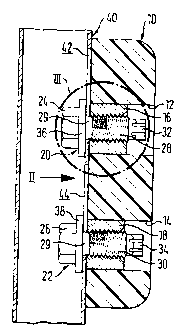
La présente invention a pour objet un dispositif de fixation servant à fixer un premier élément à un deuxième élément; celui-ci comporte au moins un organe de fixation fileté avec une tête à l'une de ses extrémités, la tête en question comportant des surfaces de manoeuvre pour outil d'entraînement, une tige filetée, l'autre extrémité de cette tige comportant des surfaces de manoeuvre pour outil d'entraînement; le premier élément est percé d'au moins un alésage permettant le vissage de la tige filetée en question aux fins de montage préliminaire, la tête se trouvant éloignée de la surface de contact du premier élément; le deuxième élément, de préférence fabriquée d'une tôle de faible épaisseur, comporte au moins une ouverture de forme allongée, celle-ci comportant une première région destinée à recevoir la tête du boulon à vis, et une deuxième région plus petite destinée à recevoir la tige filetée du boulon en question, tandis que la tête du boulon en question prend appui sur le rebord extérieur de l'ouverture en question.


Abrégé anglais


A fastening assembly for fastening a first member to a second member
comprising
- at least one threaded fastener having a head at one end thereof, said head
having engagement surfaces for a tool, a threaded shank, the other end of
said shank having engagement surfaces for a tool,
- at least one receiving bore in the first member into which said threaded shank
is threaded in a pre-mounted state from one end thereof, with the head being
spaced from the associated surface of the first member,
- the second member being preferably of thin sheet material and having at least
one elongated opening, said opening having a first portion adapted to allow
the entrance of said head and a smaller portion adapted to accommodate said
shank while said head grips behind the edge of said opening.

Revendications

Note : Les revendications sont présentées dans la langue officielle dans laquelle elles ont été soumises.


-7-
The embodiments of the invention in which an exclusive property or privilege
is claimed are
defined as follows:
1. A fastening assembly, comprising:
a first member having at least one threaded bore defined therein and a first
engagement surface;
at least one threaded fastener having a head at a first end thereof and a
threaded
shank connected at a first end thereof to said head and having a second
opposite end which
has means thereon for engaging a rotary tool, said at least one threaded
fastener being
disposed within said at least one threaded bore of said first member as a
result of threaded
engagement of said threaded shank of said at least one threaded fastener with
said at least one
threaded bore of said first member whereby said head of said at least one
threaded fastener
is separated from said first engagement surface of said first member so as to
define a space
therebetween; and
a second member comprising a panel having first and second engagement
surfaces and at least one elongated opening having a first larger portion for
accommodating
said head of said at least one threaded fastener and a second smaller portion
for
accommodating said threaded shank of said at least one threaded fastener so as
to permit said
second member panel to be disposed within said space defined between said head
of said at
least one threaded fastener and said first engagement surface of said first
member when said
head of said at least one threaded fastener is initially inserted through said
first larger portion
of said at least one elongated opening of said second member and when said
first end of said
threaded shank is subsequently moved from said first larger portion of said at
least one
elongated opening of said second member and into said second smaller portion
of said at least
one elongated opening of said second member, whereby when said at least one
threaded

-8-
fastener is subsequently tightened as a result of rotary engagement of a
rotary tool with said
second opposite end of said at least one threaded fastener, said head of said
at least one
threaded fastener will be engaged with said first engagement surface of said
second member
while said second engagement surface of said second member will be engaged
with said first
engagement surface of said first member.
2. The fastener assembly as set forth in claim 1, wherein:
said threaded shank of said at least one threaded fastener has a left-hand
thread
provided thereon.
3. The fastener assembly as set forth in claim 1, further comprising:
insert means fixedly disposed within said first member and having an internal
thread defined therein so as to define said at least one threaded bore within
said first member.
4. The fastener assembly as set forth in claim 3, wherein:
said insert means is fixedly disposed within said first member by an
interference
fit.
5. The fastener assembly as set forth in claim 1, further comprising:
coating means disposed upon said threaded shank of said at least one threaded
fastener for increasing adherence of said at least one threaded fastener
within said at least one
threaded bore of said first member.
6. The fastener assembly as set forth in claim 1, wherein:
said head of said at least one threaded fastener has means for engaging a
rotary
tool which comprises external hexagonal facets defined upon said head.

-9-
7. The fastener assembly as set forth in claim 1, wherein:
said first member has two threaded bores defined therein;
said second member has two elongated openings defined therein; and
said at least one threaded fastener comprises two threaded fasteners
respectively
threadedly engaged within said two threaded bores of said first member.
8. The fastener assembly as set forth in claim 1, wherein:
said first member comprises an automotive airbag sensor; and
said second member comprises an automotive support panel.
9. The fastener assembly as set forth in claim 7, wherein:
said elongated openings of said second member have substantially keyhole
configurations which define said first larger and second smaller portions
thereof.
10. The fastener assembly as set forth in claim 1, wherein:
said second member comprises a hollow portion; and
said head of said at least one threaded fastener is disposed internally within
said
hollow portion of said second member while said second end of said at least
one threaded
fastener is disposed internally within said at least one threaded bore of said
first member such
that said head and second end portions of said at least one threaded fastener
do not project
externally of said first and second members.
11. A method of assembling, comprising the steps of:
providing a first member with at least one threaded bore and a first
engagement
surface;
pre-assembling at least one threaded fastener, having a head and a threaded

-10-
shank connected at a first end thereof to said head and having a second
opposite end, within
said at least one threaded bore of said first member as a result of threaded
engagement of said
at least one threaded fastener within said at least one threaded bore of said
first member such
that said head of said at least one threaded fastener is separated from said
first engagement
surface of said first member so as to define a space therebetween;
providing a second member comprising a panel with first and second
engagement surfaces and at least one elongated opening having a first larger
portion for
accommodating said head of said at least one threaded fastener and a second
smaller portion
for accommodating said threaded shank of said at least one threaded fastener;
inserting said head of said at least one threaded fastener through said first
larger
portion of said at least one elongated opening of said second member panel;
moving said at least one threaded fastener and said first member relative to
said
second member such that said first end of said threaded shank of said at least
one threaded
fastener is moved from said first larger portion of said at least one
elongated opening of said
second member and into said second smaller portion of said at least one
elongated opening
of said second member and said panel of said second member is disposed within
said space
defined between said head of said at least one threaded fastener and said
first engagement
surface of said first member; and
threadedly tightening said at least one threaded fastener within said at least
one
threaded bore of said first member such that said head of said at least one
threaded fastener
will be engaged with said first engagement surface of said second member while
said second
engagement surface of said second member will be engaged with said first
engagement
surface of said first member.
12. The method as set forth in claim 11, wherein:

-11-
said threaded shank of said at least one threaded fastener is provided with a
left-hand thread.
13. The method as set forth in claim 11, further comprising the steps of:
threadedly engaging said at least one threaded fastener within said at least
one
threaded bore of said first member, during said pre-assembling step, from said
second end of
said at least one threaded fastener by means of a left-hand drive; and
threadedly engaging said at least one threaded fastener within said at least
one
threaded bore of said first member, during said tightening step, by said head
of said at least
one threaded fastener by means of right-hand drive.
14. The method as set forth in claim 12, wherein:
said head of said at least one threaded fastener has a hexagonal external
configuration so as to facilitate said threaded engagement of said at least
one threaded fastener
within said at least one threaded bore of said first member and said second
end of said at least
one threaded fastener is provided with a Torx-portion for also facilitating
said threaded
engagement of said at least one threaded fastener within said at least one
threaded bore of
said first member.
15. The method as set forth in claim 11, further comprising the step of:
providing an internally threaded insert within said first member so as to
define
said at least one threaded bore within said first member.
16. The method as set forth in claim 15, further comprising the step of:
fixedly disposing said threaded insert within said first member by an
interference fit.

-12-
17. The method as set forth in claim 11, further comprising the step of:
providing a coating upon said threaded shank of said at least one threaded
fastener for increasing the adherence of said at least one threaded fastener
within said at least
one threaded bore of said first member.
18. The method as set forth in claim 11, further comprising the steps of:
providing said first member with two threaded bores;
providing said second member with two elongated openings; and
threadedly engaging two threaded fasteners within said two threaded bores of
said first member.
19. The method as set forth in claim 11, wherein:
said first member comprises an automotive airbag sensor; and
said second member comprises an automotive support panel.
20. The method as set forth in claim 11, wherein:
said at least one elongated opening of said second member has a substantially
keyhole configuration defining said first larger and second smaller portions
thereof.

Description

Note : Les descriptions sont présentées dans la langue officielle dans laquelle elles ont été soumises.


CA 02245255 2001-11-20
FASTENING ASSEMBLY FOR FASTENING A FIRST MEMBER TO A SECOND
MEMBER
The invention refers to a fastening assembly for fastening a first member to a
second member.
When fastening a sensor, e.g. for an airbag, it is required that the fastener
means, for example,
one or a plurality of threaded fasteners, must not project beyond the sensor,
otherwise there
is a danger that the safety belt which is attached to a column of the car body
may contact the
end of a solid fastener and thus may be damaged. A fastening of such a housing
from the
opposite side normally is not possible as the hollow column does not admit
access to the
interior thereof.
The invention provides a fastening assembly consisting of a member to be
fastened, in
particular a housing for a sensor and a support member which allows a safe and
extremely
simple and quick fastening without leaving unnecessarily protruding parts.
The invention in one aspect provides a fastening assembly, comprising a first
member having
at least one threaded bore defined therein and a first engagement surface, at
least one threaded
fastener having a head at a first end thereof and a threaded shank connected
at a first end
thereof to the head and having a second opposite end which has means thereon
for engaging
a rotary tool, the at least one threaded fastener being disposed within the at
least one threaded
bore of the first member as a result of threaded engagement of the threaded
shank of the at
least one threaded fastener with the at least one threaded bore of the first
member whereby
the head of the at least one threaded fastener is separated from the first
engagement surface
of the first member so as to define a space therebetween. A second member
comprises a

CA 02245255 2001-11-20
-1.A -
panel having first and second engagement surfaces and at least one elongated
opening having
a first larger portion for accommodating the head of the at least one threaded
fastener and a
second smaller portion for accommodating the threaded shank of the at least
one threaded
fastener so as to permit the second member panel to be disposed within the
space defined
between the head of the at least one threaded fastener and the first
engagement surface of the
first member when the head of tile at least one threaded fastener is initially
inserted through
the first larger portion of the at least one elongated opening of the second
member and when
the first end of the threaded shank is subsequently moved from the first
larger portion of the
at least one elongated opening of t:he second member and into the second
smaller portion of
the at least one elongated opening of the second member. When the at least one
threaded
fastener is subsequently tightened as a result of rotary engagement of a
rotary tool with the
second opposite end of the at least one threaded fastener, the head of the at
least one threaded
fastener will be engaged with the first engagement surface of the second
member while the
second engagement surface of the second member will be engaged with the first
engagement
surface of the first member.
Another aspect of the invention relates to a method of assembling such a
fastener system.
More particularly, the fastening assembly, according to the invention,
provides a threaded
fastener which is accommodated by a through-going bore of the member, e.g.
sensor

CA 02245255 1998-08-18
-2-
housing. The threaded fastener has a head at one end thereof which may be
additionally formed with a flange portion serving as a washer. The threaded
shank of
the fastener is accommodated by an inner thread of the bore and has engagement
surfaces for a tool at the free end thereof, e. g. a so-called Torx-portion.
The second
member which is preferably of thin sheet material, e. g. a column of the body
of an
automobile, has an opening or a hole which comprises two portions, namely a
larger
portion allowing the passage of the fastener head and a smaller sized portion
which
allows the head to grip behind the edge of the hole while contemporarily
accommodating the fastener shank. The fastener is pre-assembled in the member
such that the head is spaced from the associated surface of the member.
According
to an embodiment of the invention, the fastener shank can be threaded into an
insert
which for example forms an interference fit with the bore. If, however, the
member
is of metallic material in the area of the bore, the bore can be provided with
an inner
thread. In any case it is appropriate if the thread of the shank has an
adhering portion
by which the threaded fastener is held in the pre-position. With the pre-
mounted
threaded fastener the member is then brought into engagement with the support
member, with the head being introduced through the larger portion of the hole.
Thereafter, the member is displaced along the outer surface of the support
member
so that the head grips behind the edge of the hole, and the shank enters the
smaller
portion thereof. Now, the threaded fastener can be tightened in that the tool
engages
the end of the shank. When tightened the head of the fastener engages the
inner side
.../3

CA 02245255 1998-08-18
-3-
of the sheet material of the support member. It is understood that the
threading
movement at the end of the shank is opposite to that at the end of the head.
As the
most screw drivers normally are turning right-hand, it is recommended
according to
an embodiment of the invention to provide the threaded shank with a left hand
thread. For the pre-assembling in this case a driver is necessary which turns
left
hand.
If as explained above a protruding of the fastener is not desired it must be
taken care
that sufficient space is prevailing for the engagement of the driver. If an
insert is
used the space between shank and wall of the bore is automatically larger. If,
however, the fastener is directly threaded into the bore, the bore preferably
has an
enlarged portion at the end opposite to the fastener head to allow engagement
of the
screw driver.
The hole in the support member preferably has the shape of a keyhole with the
smaller portion being below the larger one.
The fastener assembly according to the invention allows a pre-assembling of
the
member with the threaded fastener so that the final assembling can be carried
out
within shortest time. The portion of the shank which is free of a thread
adjacent to
the head thus cannot be damaged which would not allow an assembling or a
.../4

CA 02245255 1998-08-18
-4-
threading. For example, the fastener shank can have a clearance with respect
to the
wall of the hole in order to allow the precise positioning of the member. The
fastener
assembly according to the invention for example allows the attachment of the
housing of an airbag sensor to the column such that unnecessarily protruding
parts
are avoided. The fastener assembly according to the invention is extremely
simple
structured. A simple threaded fastener is used only having the particularity
that the
end of the shank is provided with engagement surfaces for a tool. A nut which
normally is used for the screw attachment is not necessary.
An embodiment example is subsequently explained along accompanying drawings.
Fig. 1 shows a cross section through an attachment of an airbag sensor to a
column
of the body of an automotive vehicle.
Fig. 2 shows a view on the assembly of Fig. 1 in the direction of arrow A.
Fig. 3 shows a detail B of Fig. 1 without the column and in a pre-assembled
condition of the sensor housing with a threaded fastener.
./5

CA 02245255 2001-11-20
By cross hatching in Fig. 1 the housing 10 of an airbag sensor is indicated.
The housing 10
has two through-bores 12, 14 into which inserts 16 and 18 are inserted by an
interference fit.
The inserts 16, 18 have an inner thread.
Threaded fasteners 20 and 22 are provided with a head 24, 26, threaded shanks
28, 30 and
ends 32, 34. The threaded shank is threaded into the inner thread of the
inserts 16, 18. The
ends 32, 34 of the shank have a Torx-portion. The heads 24, 26 have integrally
formed radial
flanges 36, 38. A non-threaded portion 29 joins the heads 24, 26.
A column 40 of a body of an automotive vehicle not shown in detail is hollow
and formed
of sheet material. At the inner side the column 10 has two holes 42, 44 in
vertical alignment.
The holes 42, 44 are shaped like a keyhole with an upper circular larger
portion 46, 48 and
a smaller portion 50, 52 below the larger position. The larger portion is so
dimensioned that
the head 24, 24 with flange 3Ei, 38 can be inserted. The smaller portion S0,
S2 is
dimensioned such that the flange may grip behind the edge of the hole 42, 44
as can be seen
in Figs. 1 and 2.
In Fig. 3 two different embodiments are to be seen. In the lower portion of
Fig. 3 the
illustration corresponds to that of~ Fig. 1. In the upper portion of Fig. 3
the insert 16 is
omitted. Rather, bore 12a has an inner thread into which the threaded shank 28
is threaded
immediately. In order to allow the engagement of a screwdriver with the Torx-
portion 32 in
Fig. 3 the bore 12a is provided with an enlarged portion 12b. In Fig. 3 it can
be finally seen
that the fastener 20 has a pre-assembled position wherein flange 36 is spaced
a distance from
the associated surface of the housing, the distance being somewhat larger than
the thickness

CA 02245255 2001-11-20
-6-
of the sheet material into which the holes 42, 44 are formed. The shank is
partially provided
with a plastic coating 60 which allows the fastener 20 to remain in the pre-
assembled
position. The coating 60 not only secures the pre-assembled state, but also
locks the screw
when finally tightened as shown in Fig. 1.
The shank 28 for example, has a left hand thread so that during pre-assembling
the fastener
is threaded into bore 12 by a left hand screwdriver. In the pre-assembled
state the sensor
housing 10 is brought against column 40 with the heads 24, 26 inserted through
the portion
46, 48 of holes 42, 44. Then the hausing can be released so that the shank 28,
30 enters the
smaller portion 50, 52 of hole 42.. 44 and flange 36, 38 grips behind the edge
of the hole.
Now the fastener 20, 22 can be tightened by a right hand screwdriver in order
to attach the
housing 10 tightly to column 40. The end of the shaft does not project beyond
the housing
so that a damage of the safety belt does not occur.

Dessin représentatif
Une figure unique qui représente un dessin illustrant l'invention.
États administratifs

2024-08-01 : Dans le cadre de la transition vers les Brevets de nouvelle génération (BNG), la base de données sur les brevets canadiens (BDBC) contient désormais un Historique d'événement plus détaillé, qui reproduit le Journal des événements de notre nouvelle solution interne.

Veuillez noter que les événements débutant par « Inactive : » se réfèrent à des événements qui ne sont plus utilisés dans notre nouvelle solution interne.

Pour une meilleure compréhension de l'état de la demande ou brevet qui figure sur cette page, la rubrique Mise en garde , et les descriptions de Brevet , Historique d'événement , Taxes périodiques et Historique des paiements devraient être consultées.

Historique d'événement

Description Date
Inactive : CIB de MCD 2006-03-12
Le délai pour l'annulation est expiré 2004-08-18
Lettre envoyée 2003-08-18
Accordé par délivrance 2002-12-03
Inactive : Page couverture publiée 2002-12-02
Lettre envoyée 2002-09-26
Exigences de modification après acceptation - jugée conforme 2002-09-26
Modification après acceptation reçue 2002-09-03
Préoctroi 2002-09-03
Inactive : Taxe finale reçue 2002-09-03
Un avis d'acceptation est envoyé 2002-03-05
Lettre envoyée 2002-03-05
Un avis d'acceptation est envoyé 2002-03-05
Inactive : Approuvée aux fins d'acceptation (AFA) 2002-02-21
Modification reçue - modification volontaire 2001-11-20
Inactive : Dem. de l'examinateur par.30(2) Règles 2001-07-20
Demande publiée (accessible au public) 1999-02-19
Inactive : Certificat de dépôt - RE (Anglais) 1998-12-08
Inactive : CIB attribuée 1998-12-02
Inactive : CIB en 1re position 1998-12-02
Inactive : CIB attribuée 1998-12-02
Symbole de classement modifié 1998-12-02
Inactive : Transfert individuel 1998-10-26
Inactive : Correspondance - Formalités 1998-10-26
Inactive : Lettre de courtoisie - Preuve 1998-10-13
Inactive : Certificat de dépôt - RE (Anglais) 1998-10-07
Exigences de dépôt - jugé conforme 1998-10-07
Demande reçue - nationale ordinaire 1998-10-06
Exigences pour une requête d'examen - jugée conforme 1998-08-18
Toutes les exigences pour l'examen - jugée conforme 1998-08-18

Historique d'abandonnement

Il n'y a pas d'historique d'abandonnement

Taxes périodiques

Le dernier paiement a été reçu le 2002-08-13

Avis : Si le paiement en totalité n'a pas été reçu au plus tard à la date indiquée, une taxe supplémentaire peut être imposée, soit une des taxes suivantes :

  • taxe de rétablissement ;
  • taxe pour paiement en souffrance ; ou
  • taxe additionnelle pour le renversement d'une péremption réputée.

Veuillez vous référer à la page web des taxes sur les brevets de l'OPIC pour voir tous les montants actuels des taxes.

Historique des taxes

Type de taxes Anniversaire Échéance Date payée
Requête d'examen - générale 1998-08-18
Taxe pour le dépôt - générale 1998-08-18
Enregistrement d'un document 1998-10-26
TM (demande, 2e anniv.) - générale 02 2000-08-18 2000-08-09
TM (demande, 3e anniv.) - générale 03 2001-08-20 2001-08-03
TM (demande, 4e anniv.) - générale 04 2002-08-19 2002-08-13
Taxe finale - générale 2002-09-03
Titulaires au dossier

Les titulaires actuels et antérieures au dossier sont affichés en ordre alphabétique.

Titulaires actuels au dossier
ITW AUTOMOTIVE PRODUCTS GMBH & CO. KG
Titulaires antérieures au dossier
ANDREAS JAKOB
LOTHAR BREHMER
Les propriétaires antérieurs qui ne figurent pas dans la liste des « Propriétaires au dossier » apparaîtront dans d'autres documents au dossier.
Documents

Pour visionner les fichiers sélectionnés, entrer le code reCAPTCHA :


Pour visualiser une image, cliquer sur un lien dans la colonne description du document. Pour télécharger l'image (les images), cliquer l'une ou plusieurs cases à cocher dans la première colonne et ensuite cliquer sur le bouton "Télécharger sélection en format PDF (archive Zip)" ou le bouton "Télécharger sélection (en un fichier PDF fusionné)".

Liste des documents de brevet publiés et non publiés sur la BDBC .

Si vous avez des difficultés à accéder au contenu, veuillez communiquer avec le Centre de services à la clientèle au 1-866-997-1936, ou envoyer un courriel au Centre de service à la clientèle de l'OPIC.


Description du
Document 
Date
(aaaa-mm-jj) 
Nombre de pages   Taille de l'image (Ko) 
Abrégé 1998-08-18 1 21
Description 1998-08-18 6 179
Dessins 1998-08-18 1 40
Revendications 1998-08-18 2 34
Description 2001-11-20 7 235
Revendications 2001-11-20 6 219
Page couverture 1999-03-17 2 73
Dessin représentatif 2002-10-30 1 13
Dessins 2002-09-03 1 34
Page couverture 2002-10-30 1 45
Dessin représentatif 1999-03-17 1 16
Certificat de dépôt (anglais) 1998-10-07 1 163
Courtoisie - Certificat d'enregistrement (document(s) connexe(s)) 1998-12-09 1 115
Certificat de dépôt (anglais) 1998-12-08 1 163
Rappel de taxe de maintien due 2000-04-19 1 111
Avis du commissaire - Demande jugée acceptable 2002-03-05 1 166
Avis concernant la taxe de maintien 2003-09-15 1 174
Correspondance 2002-09-03 1 37
Correspondance 2002-09-26 1 9
Correspondance 1998-10-13 1 31
Correspondance 1998-10-26 3 98