Note : Les descriptions sont présentées dans la langue officielle dans laquelle elles ont été soumises.
: CA 0224~347 1998-09-23
BAC 140 - Nester, Reynolds
ROBOTIC WELDING
FIELD OF THE INVENTION
The present invention relates to robotic welding, and more particularly, to robotic welding
of a header on the co-planar ends of a group of tubes for fluid-tight seals.
BACKGROUND OF THE INVENTION
Heat exchangers and other devices typically include a stack of bent tubes connected at
- their ends to flat tubesheets that are welded to another sheet metal product to form a fluid header.
The tube ends and flat tubesheets must usually be welded, and the welds must not only provide a
joint with sufficient structural ~lleng~l to join the pieces, but must also provide a water or fluid-
tight seal so that the fluid may l~ rer between the header and the individual tubes without
leaking.
In a typical coil for a heat exchanger, there may be more than fifty tubes to be welded to
the tubesheet. Considering that there are typically two similar headers for each coil, there may
be well over one-hundred welds to be performed. Manual welding of so many joints is time
consuming and therefore potentially expensive. However, implementation of robotic welding has
been difficult. Given the need for fluid tight seals, it is n~cess~ry that each weld completely
surround each junction of a tube end and the tubesheet. Given the size of the coils, manipulation
of the coil for accurate welding has been problematic, and it is difficult and ~ensive to attempt
to make a fixture that would hold such bulky workpieces repeatedly and consistently in the same
position with respect to a welding m~rllin~ so that such fluid-tight welds could be produced.
Attempts to achieve consistent, reproducible welds in mass production through use of
commercially available robotic systems have also met with problems. It has remained difficult to
achieve acceptable fluid-tight welds in successive combinations of tubes and tubesheets.
SUMMARY OF THE INVENTION
The present invention addresses the need for efficient and accurate welding of a bulky
object, such as a coil with headers for use in a heat exchanger. One object of the present
CA 0224~347 1998-09-23
BAC 140 - Nester, Reynolds
invention is to provide for accurate robotic welding of two workpieces without requiring a fixture
that would define the robot's coordinate system.
The present invention provides a method of making a heat exchanger having tubes with
inlet and outlet headers welded to the tubes. The method comprises the steps of providing a
planar tubesheet to form part of the inlet header, and providing a planar tubesheet to form part of
the outlet header. Each tubesheet has a perimeter. Each tubesheet also has a first edge portion, a
second edge portion and a third edge portion along the perimeter of the tubesheet. The first and
second edge portions are substantially co-linear, and the third edge portion intersects a line
through the first and second edges. Each tubesheet has a substantially planar surface with interior
edges defining interior holes to receive the ends of the tubes. A robotic welding system is
provided including a sensor, a welding apparatus and means for controlling the movement and
operation of the welding apparatus. The control means accepts input from the sensor. A
reference origin is defined along a line through the first and second edge portions of the tubesheet
and a line through the third edge portion and perpendicular to the line through the first and
second co-linear edge portions. A reference three-dimensional coordinate system is provided
having the reference origin. The reference three-dimensional coordinate system includes
reference weld locations for the tubesheet based on distances from the reference origin, so that
movement of the welding apparatus may be based upon the reference weld locations and reference
three-dimensional coordinate system. One of the tubesheets is scanned with the robotic system
sensor a sufficient number of times to define an actual origin lying along a line through the first
and second edge portions and a line through the third edge portion and perpen~ r to the line
through the first and second co-linear edges. The robotic system correlates the actual origin and
the reference origin. The welding appal~lus of the robotic system is moved to weld the tubesheet
and the tubes together. The positions of the welds are based upon the location of the actual
origin.
BRIEF DESCRIPTION OF THE DRAWINGS
FIG. 1 is a perspective view of a coil of tubes with inlet and outlet headers at one end,
with one of the headers shown in exploded view.
CA 0224~347 1998-09-23
BAC 140 - Nester, Reynolds
FIG.2is an enlarged view of the header end of the coil of FIG.l.
FIG.3is a partial top plan view of a welding area, showing part of a tubesheet and part of
a coil in relation to a robotic welding apparatus, the tubesheet and part of the coil being enlarged
with respect to the robotic welding apparatus, the elements being shown schematically.
FIG. 4 is a schematic elevation of part of a robotic welding apparatus and tubesheet.
FIG.5is an elevation of a tubesheet of the present invention.
FIG.6is a perspective view of an alternative tubesheet of in the present invention,
showing a reference coordinate system in place on the tubesheet.
FIG. 7 is an elevation of a tubesheet showing the locations of the first two search points
located through the method of the present invention, and showing the preliminary position of one
of the axes determined by the robotic system.
FIG. 8 is an elevation of the tubesheet of FIG. 7 showing the location of the third search
point located through the method of the present invention and showing the shift of the origin and
axes to account for the third search point.
FIG.9is a perspective view of the tubesheet of FIGS. 7-8, showing that the coordinate
system and origin based on the locations of the first three search points can be askew on the
tubesheet surface.
FIG.lOis a perspective view of the tubesheet of FIGS. 7-9, showing a possible location
of the fourth search point and the proper ~lignment of the actual coordinate system based upon
the first four search points.
FIG.llis a perspective view of the tubesheet of FIGS. 7-10, showing a cover positioned
on the tubesheet and the positions of the search points for welding the cover onto the tubesheet.
DETAILED DESCRIPTION
As shown in FIG.l, a coil or tube bundle 10 for use in a heat exchanger typically
includes a plurality of horizontal rows 12 of tubes 14 bent into a serpentine pattern. The rows of
tubes are assembled as a bundle or group of overlying rows. The vertical planes of overlying
rows 12 may be slightly offset horizontally as shown. Typical tube arrangements may carry
cooling water, oil, ethylene glycol solutions, and other fluids or refrigerants in a closed,
CA 0224~347 1998-09-23
BAC 140 - Nester, Reynolds
pressurized system. Design pressure in such systems may be on the order of 280 psig, and test
pressures may be on the order of 350 psig. In some environments, it may be n~cessary or
desirable for the coil or tube bundle 10 to meet the ASME Boiler and Pressure Vessel Code.
In the illustrated embodiment, the tubes are continuous steel tubing, formed into the
serpentine shape and welded into the assembly. The complete assembly may be hot-dip
galvanized after fabrication.
At one end 16 of the illustrated tube bundle 10, each horizontal row 12 of continuous tube
14 has an inlet end 18 and an outlet end 20. As illustrated, the inlet and outlet ends of overlying
rows of tubes are slightly offset in a horizontal direction, so that the inlet ends of adjacent rows
are in different vertical planes, and so that the inlet ends of alternating rows are vertically
aligned, as are the outlet ends of alternating rows. The inlet ends 18 are all connected to an inlet
header 22 and the outlet ends 20 are all connPctPd to an outlet header 24.
The illustrated inlet header 22 is conn~ct~d to an inlet pipe 26 and the outlet header 24 is
connected to an outlet pipe 28. The inlet pipe 26 may, for example, be conn~cted to receive an
industrial process fluid to be cooled, and the outlet pipe 28 may be connected to deliver a cooled
industrial process fluid back to the industrial process equipment. Similarly, the inlet pipe 26
could be connected to receive a vapor to be condensed, and the outlet pipe 28 may deliver the
condensed liquid back into the industrial process line.
Each header 22, 24 comprises an inlet and outlet cover 30, 32 and an inlet and outlet
tubesheet. FIGS. 1 and 2 illustrate the inlet tubesheet 40; the outlet tubesheet 41 is substantially
the same as the inlet tubesheet, and the following description of the inlet tubesheet 40 applies as
well to the outlet tubesheet 41. As shown in the exploded view of FIG. 2, the inlet tubesheet 40
has a flat surface and has a plurality of circular holes or openings 44. In the illustrated
embodiment, there are two groups of openings or holes 44, so that alternating openings are
aligned parallel with an edge of the tubesheet and adjacent openings are not aligned parallel to an
edge of the tubesheet. Each opening or hole 44 of the inlet tubesheet 40 is connected to an inlet
end 18 of one tube 14. The outlet tubesheet 41 has similar openings 44 connected to the outlet
ends 20 of the tubes 14.
CA 0224~347 1998-09-23
BAC 140 - Nester, Reynolds
The ends 18, 20 of the tubes 14 at the junctures with the tubesheets 40, 41 at the openings
44 are connected to the tubesheets by welding. For use in the described environments, that is, in
vapor condensing and fluid cooling, the welds must not only connect the parts into the complete
assembly, but must also be fluid tight to prevent leaks. Creating such welds in such an
environment as that illustrated in FIGS. 1-2, where there are over one-hundred junctions of tube
ends and tubesheets 40, is labor intensive if done m~nll~lly. It has been difficult to achieve
acceptable welding with traditional robotic welding since the tube bundle is so large and bulky,
often measuring from three to eighteen feet in length, from three to five feet wide, and from
three to five feet high, and weighing on the order of 1500 - 3000 pounds, although it should be
understood that these values are given for purposes of illustration only. The tubesheets may be
about five inches wide and from about thirty-three to sixty-six inches long and about one-quarter
inch thick, for example, and again these values are given for purposes of illustration only. With
parts of such proportions, it is difficult to achieve consistent positioning of the parts relative to
the robotic welding apparatus. Such bulky parts are not easily carried or supported by a
positioning fixture that would assure consistent proper orientation of the tubes and tubesheets for
the start of welding. Without exact, consistent and repeatable positioning of the part and the
welding unit, there is a chance for there to be slight variations in relative position that translate
into potential illl~loper positioning of the welded junctions, with the potential for leaky joints, an
unacceptable result.
The present invention provides a method of robotic welding such junctions that assures
exact, consistent and repeatable results. The present invention achieves these results by assuring
that the robotic welding commences at an origin point that is determined for each tubesheet
individually before welding commences. In addition, the process ensures that the robotic welding
frame of reference, that is, the reference three-dimensional Cartesian coordinate system, overlies
and is coincident with the actual three-dimensional spatial orientation of the tubesheet. The
present invention also utilizes this data in welding the covers on the tubesheets to complete the
headers. The present invention may be used to m~nllf~c~lre sel~e~ e tube bundles of the type
illustrated in FIGS. 1-2, as well as other styles of tube bundles and headers, such as a tube bundle
with straight-through tubes and headers on both ends of the tubes; moreover, the principles of the
CA 0224~347 1998-09-23
BAC 140 - Nester, Reynolds
present invention may be applied to other welding operations involving heavy, bulky or
cumbersome articles.
The present invention achieves accurate welding of two workpieces together through the
following steps. First, workpieces to be welded are provided. These workpieces may be, for
example, a planar end or tubesheet 40 to form part of a header and the second workpiece may be
an arrangement of tubes 14 such as a coil bundle 10 comprised of a plurality of tubes with ends,
such as inlet ends 18 and outlet ends 20, to be placed through mating holes in the inlet tubesheet
40 and outlet tubesheet 41 and have their surfaces welded to the edges of the holes.
Alternate tubesheets for use with the present invention are illustrated in FIGS. 5-6. It
should be understood that the following description applies to both the outlet tubesheets 41 and
inlet tubesheets 40, although the tubesheet is identif1ed with reference numeral 40 in each of
FIGS. 4-11. Each illustrated tubesheet 40 has a top edge 52, a bottom edge 54, a first side edge
56 and a second side edge 58. Each tubesheet 40 is substantially rectangular, with the side edges
56, 58 being longer than the top 52 and bottom 54 edges. The top and bottom edges 52, 54 are
roughly parallel to each other and roughly perpendicular to the two side edges 56, 58. Each
tubesheet 40 has a substantially planar face 60 between the edges 52, 54, 56, 58 and a plurality of
interior edges 64 defining the circular holes 44. Each circular hole 44 receives the end of one
coil tube 14, such as the inlet end 18 or outlet end 20, and the tubesheets 40, 41 are to be welded
to the inlet and outlet ends 18, 20 of the coil tubes 14 along the edges 64 of each circular hole 44.
It should be understood that the size and shape of the illustrated tubesheet 40 are given for
purposes of illustration only; a tubesheet may have many more or fewer holes arranged
dirrerelllly, and the tubesheet may be shaped dirr~lelllly.
As shown in FIGS. 5, each illustrated tubesheet 40 has at least two substantially co-linear
segments or edge portions 70, 72 and at least one additional third segment or edge portion 74
perpendicular to a line through the f1rst and second segments or edge portions 70, 72. All of the
segments or edge portions 70, 72, 74 are along the perimeter, that is, along the exterior edges 52,
54, 56, 58 of the tubesheet 40. Each segment or edge portion 70, 72, 74 corresponds with a
cutout or notch 75 in one of the exterior edges 52, 54, 56, 58 of the tubesheet 40, formed by
precision cutting out a section of the respective exterior edge of the tubesheet. The precision
CA 0224~347 1998-09-23
BAC 140 - Nester, Reynolds
cutting may be through ~ ing, laser cutting or the like. In the embodiment of FIG. 5, there
are two cutouts 75 in or along one exterior edge 56 and each has at least one point, shown at
"P1" and "P2" in FIGS. 7-9, that is co-linear with the other, although in the illustrated cutouts 75
the co-linear points P1 and P2 comprise short line segments; the third cutout has a perpendicular
point, shown at "P3" in FIGS. 8-9, that is, a point that lies along a line that is substantially
perpendicular to a line through the first and second co-linear points Pl and P2.In the tubesheet of FIG. 6, both long exterior edges 56, 58 have the first and second co-
linear segments or edge portions 70, 72 and co-linear points, and both short top and bottom
exterior edges 52, 54 have the third segments or edge portions 74 that are perpendicular to the
co-linear segments or edge portions 70, 72. As discussed below, this construction provides
greater flexibility in using the tubesheets.
The cutouts or notches 75 are each precision cut to provide a group of reference segments
or edge portions within a close tolerance for accuracy. The precision cutting may be through, for
example, ~l~lllpillg, shearing or laser cutting operations, for example. Rather than go through the
expense of machining, shearing or ~ ing the entire length of each edge of the tubesheet,
expense may be saved by assuring that the shorter cutouts or notches 75 are precisely located.
The distances between the cutouts and their orientation relative to one another should be within
close tolerances: the cutouts along the elongate exterior side edges 56, 58 should be assured of
being co-linear so that each pair may be used to establish one axis of the three dimensional
Cartesian coordinate system; the co-linear cutouts on the side edges 56, 58 should be assured of
being perpendicular to the cutouts on the top and bottom edges 52, 54; the positions of the
cutouts are preferably accurate to within tho -~n-lth~ of an inch.
In addition, the cutouts or notches 75 may be precision cut at the same time as the interior
holes 44 are cut in the tubesheet 40, with the same equipment or with equipment positioned by
the notches or the holes so that the spatial relationship between each hole and the notches is
known and can be used in prog~ ing the robotic welder. With the tubesheet 40 notches 75
and holes 44 so made, the relative positions of the notches and holes may be precisely and
consistently located. Thus, a reference origin and coordinate system can be programmed and
instructions for movement and welding can be based on the relative positions of the notches 75
CA 0224~347 1998-09-23
BAC 140 - Nester, Reynolds
and the holes 44. As long as the reference coordinate system for the tubesheet and welds
corresponds with the actual orientation of the tubesheet face 60, the welds between the tubesheet
and the coil tubes should be accurately placed and should produce a leak-proof weld.
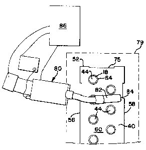
A robotic welding system 80 is used in the present invention. The robotic welding system
80, shown schematically in FIG. 4, includes a sensor 82, a welding apparatus 84 and means 86
for controlling the movement and operation of the welding apparatus 84 and the sensor 82. The
controlling means 82 accepts input from the sensor, and preferably comprises a programmable
element and compatible software, such as a coml.uler, which can be programmed with a reference
coordinate system and weld sites. One such robotic welding system that is commercially
available is sold by ABB, Inc. (Asea Brown Boveri) - Flexible Automation, Welding Systems
Division, of Ft. Collins, Colorado. A suitable robotic welder is an IRB 2400 6-axis industrial
robot M94A. This commercially available robotic welding system includes a sensor and a
welding apparatus. The sensor in this apparatus is part of the welding torch, as illustrated in
FIG. 4, so that the same manipulator arm is used for both sensing and welding the workpieces.
Two commercially available software programs that may be used as part of the controlling means
are "Arcware" welding software from ABB and "Smartac" tactile sensing software available from
ABB to interface with the "Arcware" software. This equipment and software are capable of
storing a theoretical or reference Cartesian coordinate system and reference weld locations. It
should be understood that the present invention is not limited to this robotic system or software,
and that this system and software are identified for purposes of illustration only.
The method of the present invention may include the step of providing a r~r~lel1ce three-
dimensional coordinate system 88 with a reference origin 89, shown in FIG. 6. The robotic
welding system software would also include reference weld locations for the tubesheet based on
distances from the ~eferel1ce origin 89 in the reference coordinate system 88. The lefelence weld
locations would comprise precise, predete~ 1ed distances from the reference origin 89 along
reference X, Y and Z axes, designated 83, 85, 87 respectively in FIG. 6, to which the robotic
welding apparatus must be moved, locations of its paths of travel, and locations where the
welding apparatus should be ope,a~ g to make a weld and locations where it should be turned off
to travel from joint to joint, to complete all of the desired welds. The reference coordinate
CA 0224~347 1998-09-23
BAC 140 - Nester, Reynolds
system and reference weld locations are predetermined and input and stored into the memory of
the robotic system, such as in the controlling means 86. While the above-described equipment
and software available from ABB can de~llnille an initial X-Y-Z coordinate system, the initial
coordinate system may not coincide with the plane of the face of the tubesheet, and the initial
origin may be offset from the desired position for the origin. The present invention provides a
search routine that precisely and consistently locates the origin of the tubesheet relative to the
notches to assure accurate welding of the holes which are in a fixed precise and consistent
relationship with the notches.
Before commencing sc~nning and welding, the tubesheet 40 and bundle 10 of tubes 14 are
positioned in a juxtaposed relationship for welding, with the inlet ends 18 of the tubes 14
extending slightly through the interior holes 44 in the tubesheet 40. The planar face 60 of the
tubesheet 40 is disposed in a subst~nti~lly vertical plane. The bundle 10 of tubes 14 and
tubesheet 40 are supported in this relationship free from any fixture for serially receiving and
positioning the workpieces in an identical pre-determined position relative to the robotic welding
system 80. The outlet tubesheet 41 may also be positioned at this time, with the outlet ends 20 of
the tubes 14 extending slightly through the interior holes 44 of the outlet tubesheet 41; the outlet
tubesheet may alternatively be positioned for sc~nning and welding at a later time. The
combination of tubesheet 40 and bundle 10 of tubes 14 are positioned and supported so that the
tubesheet is within a search volume or box 79, shown in phantom in FIGS. 3-4.
In the method of the present invention, the robotic welding system 80 first begins
searching from the edge of the search volume or box 79 in several directions looking for the
tubesheet. Once the tubesheet is located, the robotic welding system searches the bottom portion
of the side edge 56 of the tubesheet 40 to find the inside edge or bottom co-linear segment 72 of
the bottom co-linear cutout or notch, and then searches the bottom portion of the outside face 60
of the tubesheet 40 to de~e~ e a first point Pl that is along the bottom co-linear segment 72 of
the cutout and at the surface of the outside face 60 of the tubesheet, as shown in FIG. 7. The
first point Pl is then stored in the memory of the robotic controlling means 86. Next, the robotic
welding system 80 moves its sensor 82 to scan the top portion of the same side edge 56,
searching for the top cutout or notch 75, and locates the inside edge or top co-linear segment 70
CA 0224~347 1998-09-23
BAC 140 - Nester, Reynolds
of the top cut-out; the robotic welding system moves its sensor to scan the planar face 60 of the
tubesheet 40 to d~te~ e a second point P2 at the face of the tubesheet and on the top co-linear
segment 70, as shown in FIGS. 7-8. The second point P2 is stored in the memory of the robotic
controlling means 86.
As shown in FIG. 7, the location of these two points P1 and P2 allows one actual axis of
the face 60 of the tubesheet 40, the X-axis for example, to be d~lellllilled. In FIGS. 7-8, the
actual X-axis is designated by reference number 90. The method of the present invention
continues to determine a third point so that the actual origin can be found for the tubesheet.
As shown in FIG. 8, the robotic system sensor 82 is moved to search the top edge 52 of
the tubesheet 40 to find the inside edge or third segment 74 of the top cut-out or notch 75. This
third point P3 is stored in the memory of the robotic controlling means 86. With this position
located, the X-Y-Z coordinate system may be tr~ncl~te~l so that the Y-Z plane intersects both the
inside edge of the top cutout, that is, the third segment 74 at P3 and the previously-defined X-axis
90, and is perpendicular to the previously-defined X-axis 90. As shown in FIG. 8, the Y-axis 91,
which lies in the Y-Z plane, will lie in the same plane as point P3.
Even with the X axis 90 and Y-Z plane accurately located, the actual coordinate system
may still not be flush with the plane of the face 60 of the tubesheet 40, as shown in FIG. 9.
Accordingly, the robotic welding system 80 next determines the actual three-dimension
orientation of the planar face 60 of the tubesheet 40 relative to the robotic system coordinate
system by again sc~nning the tubesheet 40 face 60. As with points P1 and P2, it may be
desirable to search the face 60 of the tubesheet 40 near the third segment 74 before defining the
point P3 to assure that the third point is not offset from the plane of the tubesheet face 60. With
point P3 lying on the face 60 of the tubesheet, the Y-axis 91 should be co-planar with the face 60
of the tubesheet 40, and the actual origin 96 may be defined as the intersection of the X and Y
axes 90, 91. Alternatively, the robotic welding system may move the sensor 82 to locate another
point on the face 60 of the tubesheet 40 spaced from the X and Y axes 90, 91, and may store this
point in memory as P4, as shown in FIG. 10. With this point P4 dete. ,~inPc1, the robotic
controlling means software can detellllhle the complete spatial orientation of the tubesheet, and
can determine the actual position of the actual Z-axis 92 for the tubesheet, and can deL~ ille the
CA 0224~347 1998-09-23
BAC 140 - Nester, Reynolds
position of the actual origin 96 based on the orientation of the actual X, Y and Z axes 90, 91, 92.
The software can correlate the theoretical or reference coordinate system 88 and the actual
coordinate system 94, along with the coordinate system for the robotic welding system itself,
designated at 95 in FIG. 3; that is, the software can rotate the reference coordinate system 88 to
coincide with the actual coordinate system 94 for the tubesheet, and determine its position relative
to the actual coordinate system. The present invention provides for this determination to be made
independent of the position and orientation of any fixture supporting the tubesheet and coil, and
independent of any assumed position for these pieces. Instead, the dete~ ation is made based
on the position of the tubesheet 40 itself by scanning the surface of the tubesheet.
Although the actual origin 96 could be found using either a P3 that is on the face 60 of the
tubesheet 40, it may be desirable to use P4 as described to account for any bending that may
occur in the top edge of the tubesheet.
Once the precise actual spatial orientation of the tubesheet 40 is known, and the reference
coordinate system 88 is aligned or made to coincide with the actual spatial orientation of the
tubesheet 40, the welding operation can commence with the assurance that the weld points will be
located as predetermined and progr~mmPd. That is, the positions of the welds will be based upon
the location of the actual origin 96 and actual orientation of the planar face 60 of the tubesheet
relative to the robotic welding system. The robotic welding system 80 may then move its
welding apparatus 84 the prede~llllined distances along from the origin along the X, Y and Z
axes and commence welding the tubes to the tubesheet. The actual weld locations should
coincide with the preset theoretical weld locations. The method of the present invention should
allow for the production of a plurality of welded coils and tubesheets in a series, that is, one after
another in succession, with the actual origin and spatial orientation of each tubesheet being
determined and correlated with the theoretical origin. The results should be exactly positioned
welds, and these results should be consistent and repeatable.
It should be understood that the order of steps set forth above for sensing the position and
orientation of the tubesheet is given for purposes of illustration only. The order of steps may be
modified.
CA 0224~347 1998-09-23
BAC 140 - Nester, Reynolds
These steps may be incorporated into the available software, such as the "Smartac" and
"Arcware" software described above.
Once all of the welding of the tube ends to the tubesheets is completed, then the inlet and
outlet headers 22, 24 may be completed by welding the inlet and outlet covers 30, 32 to the
tubesheets 40. In FIG. 11, one cover 30 is shown, and it should be understood that the following
description of the cover and of the steps in welding the cover to the underlying tubesheet 40 apply
to the other cover as well. As shown in FIG. 11, the header cover 30 has a short top face 100
and a short bottom face 102 that are parallel to each other and perpendicular to the planar face 60
of the tubesheet 40. The cover 30 also has top and bottom edges 104, 106, and elongate side
faces 108, 110 that are parallel to each other and perpenrlic~ r to and extend between the planar
face 60 of the tubesheet 40 and to the top and bottom faces 100, 102 of the cover. An upper
cover face 112 extends between the first and second short faces 100, 102, as well, and is parallel
to the planar face 60 of the tubesheet 40. Two angled connecting faces 114, 116 connect the top
face 112 and the elongate side faces 108, 110. The elongate side faces 108, 110 have elongate
side edges 118, 120 that are generally parallel to each other and perpendicular to the top face
edge 104 and bottom face edge 106. Generally, the covers 30, 32 and tubesheets 40 are welded
together in fluid-tight connections along the top and bottom edges 104, 106 and elongate side
edges 118, 120. The present invention accomplishes this welding with robotic welding. As in
the case of welding the tube ends and tubesheets together, accurate location of the tubesheets and
covers, and relation of the located parts to a reference coordinate system are nPce~s~ry for proper
robotic welding.
In the present invention, the robotic welding equipment has stored the information as to
the locations of the tubesheets, that is, it stores information related to the actual origin and actual
orientation of the tubesheet and uses the same rererence coordinate system for the planar face 60
of the tubesheets 40 for welding the covers as for the welding of the tube ends and tubesheets.
This is advantageous since it is preferable to position the covers with reference to the interior
holes 44 rather than with the exterior edges 52, 54, 56, 58 of the tubesheets 40 since the edges
apart from the notches or cutouts may not be straight or perpen~lic~ r, and it is n~cess~ry that the
holes 44 be completely covered by the covers 30, 32.
CA 0224~347 1998-09-23
BAC 140 - Nester, Reynolds
The header cover 30 is placed on the tubesheet 40 so that all the holes 44 where the coil
tubes ends are welded to the tubesheet are covered by the cover 30 and the edges 104, 106, 118,
120 of the cover 30 are juxtaposed with the planar face 60 of the tubesheet 40. The edges of the
header cover 30 may not be exactly parallel to the tubesheet edges. Next, six searches are
performed to determine the header orientation. The six searches are as follows.
First, the controlling means 86 directs the robot scanner or sensor 82 to search or scan
one elongate face 108 of the cover 30 near one of the short faces 100, 102, such as the top short
face 100, to determine a first upper elongate face location, designated "PS" in FIG. 11. The
location is determined with respect to the actual origin 96 of the tubesheet 40 and actual
orientation of the tubesheet. Information on this first or upper elongate face location PS is stored
in the memory of the robotic control means 86.
Next, the same elongate face 108 is searched or scanned near the opposite bottom short
face 102 of the cover 30 to determine a first bottom elongate face location, designated "P6" in
FIG. 11. The location is dete~ h1ed with respect to the actual origin 96 of the tubesheet 40 and
actual orientation of the tubesheet. Information on this second or bottom elongate face location
P6 is stored in the memory of the robotic control means 86.
Next, one short face 100, 102 of the cover 30 is searched by moving the robotic scanner
or sensor 82 to dete~ le a first short face location, designated "P7" in FIG. 11 for the top face
100 of the cover 40, although the location may be for the top or bottom short face 100, 102. The
location may be determined with respect to the actual origin 96 of the tubesheet and the actual
orientation of the tubesheet. Information on this first short face location P7 may be stored in the
robotic control means 86 memory.
Next, the second elongate face 110 of the cover 30 near one side edge 120 is searched,
nearer to one of the short faces, such as the top short face 100 to determine a first upper elongate
location designated "P8" in FIG. 11. The first upper elongate location P8 is d~ellllhled with
respect to the actual origin 96 of the tubesheet 40 and the actual orientation of the tubesheet 40,
and this first upper elongate face location P8 is stored in the memory of the robot control means
86.
CA 0224~347 1998-09-23
BAC 140 - Nester, Reynolds
Next, the robot 80 moves its scanner 82 to continue to scan or search the second elongate
face 110 of the cover 40 nearer the bottom short face 102 to determine a first lower elongate face
location designated "P9" in FIG. 11. The lower elongate face location P9 is determined with
respect to the actual origin 96 of the tubesheet 40 and the actual orientation of the tubesheet and
stored in the memory of the robotic control means 86.
Finally, the robot 80 moves its scanner 82 to search the second or bottom short face 102
of the cover 30 to determine a second short face location designated "P10" in FIG. 11. The
second short face location P10 is determined with respect to the actual origin 96 of the tubesheet
40 and the actual orientation of the tubesheet, and information as to the location P10 of the
second short face 102 is stored in the memory of the robot control means 86.
With this information, the program of the control means 86 should be able to interpolate
or detellnil1e the positions of the four intersections or corners 130, 132, 134, 136 of the side
edges 118, 120, top edge 104 and bottom edge 106 so the four seams can be welded at the
junctions of the cover edges 104, 106, 118, 120 and the face 60 of the tubesheet 40. The robotic
control system 86 can determine the positions of these corners 130, 132, 134, 136 relative to the
actual origin 96 and actual orientation of the tubesheet from the stored information. The robotic
control means 86 can then move the welding apparatus 84 to positions based on the actual
locations of the corners and weld each edge 104, 106, 118, 120 to the face 60 of the tubesheet
40.
The order of searches may be changed from that described above, and welding of some
edges may be done before all the searches are completed. For example, it may be desirable to
first search one of the short faces, such as short face 100 of the cover 30 before searching one of
the elongate faces, for example, 108. And it may be desirable to weld a seam such as that
between the short face 100 and the tubesheet 40 before fini.ching the other searches.
As an example of one alternate search and weld routine for welding the cover 30 to the
tubesheet 40, the point designated P6 in FIG. 11 could first be located, followed by a search of
the bottom short face 102 to find the point designated Pio and to define the intersection
designated 134 in FIG. 11. Next, the point designated PS in F~G. 11 may be located, and the
welding apparatus 84 may be moved to weld the cover to the tubesheet face 60 along the elongate
14
CA 0224~347 1998-09-23
BAC 140- Nester, Reynolds
side edge 118. Next, the robotic system sensor 82 may be moved to search the elongate face 110
to locate the point designated P9 in FIG. 11. After searching the bottom plate or face 102, the
position of the intersection designated 136 in FIG. 11 may be determined, and the bottom short
face 102 may be welded to the tubesheet face 60 along the bottom edge 106. Next, the top part
of the right elongate face 110 may be searched to find the point designated P8 in FIG. 11,
followed by a search of the top short face 100 to find the point designated P7 in FIG. 11. The
intersections designated 130 and 132 in FIG. 11 may thus be located and the cover 30 may be
welded to the face 60 of the tubesheet along the top edge 104 and right side edge 120 of the cover
30. It may also be desirable to perform additional searches, such as at points midway along the
elongate faces 108, 110.
The software used for the robotic control means should be able to accurately find the
joints for welding using a limited number of searches and rec~lling the tubesheet plane defined
during tubesheet and tube end welding. As illustrated, the locations of the seams may be found
independent of the depth of the header, and for headers of different lengths and widths. Notably,
given the lengths of the long sides 108, 110 of the header covers, two searches are preferably
con~ ctec~ to ensure that the actual header cover orientation is found and to account for variances
in the cover; given the short lengths of the top and bottom faces 100, 102, one search should
suff1ce for these faces since even a variance of 0.5 inches over a 40 inch length would only
amount to a difference of .0625 inches over the 5 inch length of the top and bottom faces.
The illustrated tubesheet 40 has notches or cutouts 75 on both the top edge 52 and bottom
edge 54 even though only one of these two cutouts 75 is used in the searching routine. By
providing both cutouts 75, the same tubesheet could be used for either the inlet or the outlet
header simply by flipping the tubesheet around. Thus, instead of requiring different tubesheets,
one style of tubesheet may be used interchangeably on both ends of the coil.
It may be p-~;r~ d to control the positions of the ends 18, 20 of the tubes 14 in relation
to the faces 60 of the tubesheets 40, 41. Preferably, the ends 18, 20 of the tubes 14 extend a
distance of about one-half inch from the faces 60 of the tubesheets 40, 41, or within a range of
about three-eights to about five-eighths inches from the faces 60 of the tubesheets 40, 41 before
sc~nning and welding are commenced.
CA 0224~347 1998-09-23
BAC 140 - Nester, Reynolds
While only specific embodiments of the invention have been described and shown, those
in the art should recognize that various modif1cations can be made thereto and alternatives used.
In addition, it should be recognized that the present invention has applications beyond the
illustrated environment. It is, therefore, the intention in the appended claims to cover all such
modif1cations and alternatives and applications as may fall within the true scope of the invention.
16