Note : Les descriptions sont présentées dans la langue officielle dans laquelle elles ont été soumises.
CA 02245479 2000-06-22
1 "APPARATUS AND METHOD FOR
2 EXTRACTING ~4ND REPLACING BURIED PIPE"
3
4 FIELD OF THE INVENTION
The present relatE~s to apparatus and method for the simultaneous
6 extraction of old buried pipe and the insertion of new pipe. A pipe
pushing/pulling
7 device is operable within a pit and is removably attached to and stabilized
by the
8 pit-excavating machine. The method comprises using the excavating machine to
9 excavate the pit, anchor the device and power the device to pull out the old
pipe
and draw in the new pipe.
11
12 BACKGROUND OF THE INVENTION
13 As underground pipe ages or otherwise becomes inadequate for its
14 purpose, there is a neecl to replace it with new pipe. Preferably, pipe
replacement
is performed with minimal impact to the surrounding environment, be it the
16 disruption of normal traffic or the ground area needed to operate the
equipment.
17 Further, it is preferable to miinimize the time expended setting up and re-
18 positioning the equipment used i:o conduct the pipe replacement.
19 Apparatus and process exist which meet several of the above goals
with varying degrees of success. Minimizing the disruption of traffic is
21 accomplished with a method for replacing pipe without digging a trench
along the
22 entire length of pipe.
CA 02245479 2000-06-22
1 Prior art processes comprise:
2 ~ digging two pits into the ground to expose the old pipe;
3 ~ fishing a cable through the old pipe;
4 ~ using an abutting member to brace the cable against one end of
the old pipe;
6 ~ placing apparaitus in the other pit and using shoring timbers to
7 support the apparatus against the pit wall and absorb reaction
8 forces;
9 ~ pulling on the cable end and abutting member to pull the pipe
from the ground and extract it from the pit; and
11 ~ optionally, attaching new pipe to the old pipe so as
12 simultaneously pull new pipe into the bore through the ground
13 formed by the extracted old pipe.
14 The above process has been accomplished with a variety of
equipment which applies many or all of the above method steps. Apparatus
16 including that in U.S. Patent ;5,328,297 ('297) to Handford and 5,211,509
to
17 Roessler disclose various forms of cable-winches and pulley arrangements
18 comprising:
19 ~ a reaction plate for pressing or bracing against the side of the
first pit's wall adjacent the first end of the old pipe for absorbing
21 reactivE~ forces generated through pulling of the pipe;
2
CA 02245479 2000-06-22
1 ~ a pulley mounted to the reaction plate for receiving the pipe-
2 pulling cable extending out of the pipe and turning it through a
3 right angle to extend up and out of the first pit;
4 ~ a structure ea;tending up from the reaction plate to a cable
winch; and
6 ~ the winch being attached to a moveable vehicle for enabling
7 inserting of thE~ reaction plate and connecting structure into the
8 first pit.
9 The reaction plate of Roessler is a permanent non-rotatable
structure attached to the vehicle. The rigid structure of Roessler holds the
11 reaction plate stable but restriicts the positioning of the vehicle to a
position
12 directly in-line with and opposing the pipe. Further, a separate piece of
13 equipment must be provided to dig the pits.
14 Handford '297 provides an assembly which comprises a cable
winch, a downward extending leg assembly, pulley and reaction plate. The
16 assembly is releasably attached at ground surface to a front end loader for
using
17 its hydraulic power system. The reaction plate is rotatable relative to
vehicle so
18 that the vehicle may positioned anywhere around the pit. The leg assembly
19 permits vertical adjustment to match the reaction plate's depth to the
exposed
pipe. The reaction plate of Handford is dependent however upon the pit wall
21 being square to the noirmal force applied to pull the pipe. If the pit wall
is not
22 square, the reaction plate will rotate on the leg, mis-aligning the cable
pulley from
3
CA 02245479 2000-06-22
1 the pipe and adversely affecting the vertical. As with Roessler, a separate
piece
2 of equipment must be provided to dig the pits.
3 The prior art deals with non-square pit walls by using shoring.
4 Personnel enter the pit and arrange a variety of timbers to square the
reaction
plate to the pit walls. RE~lease of cable-pulling tension can dislodge or
release the
6 shoring, causing it to lose its stacked structure which then requires time-
? consuming repositioning by thE: personnel. Further, for safety reasons, use
of
8 personnel working in the pit should be minimized.
9 Neither Handford '297 nor Roessler teach nor suggest how a
pulling apparatus may be constructed for permitting the equipment to be
11 positioned closely adjaicent and freely about the pit while also
conveniently
12 stabilizing the apparatus against the pit wall without involving personnel
in a
13 significant way or eliminating the troublesome shoring.
14 Another difficulty associated with old buried pipe is that in some
instances it is necessary to initially free the pipe before it is possible to
use a
16 cable to pull the pipe from the ground. Accordingly, there is often a need
to first
17 loosen the pipe prior to pulling with the cable. One method of loosening a
stuck
18 pipe is to alternately pu:;h, then pull the pipe. This is not possible
either with the
19 prior art cable pulling apparatus described above as they do not
incorporate a
pushing reaction plate or mean:. for generating a pushing force.
4
CA 02245479 2000-06-22
1 In another' approach disclosed by Handford in US Patent 5,205,671
2 ('671), a hydraulic pushing device is provided which pushes old pipe out of
the
3 ground using a hydraulic ram. The rams can also pull the old pipe from the
4 ground. A pulling pipe is extended through the old pipe and an abutment
member is used to bear against: the distal end of the old pipe. New pipe is
bolted
6 to the abutment member and is pulled into the ground as the old pipe is
drawn or
7 pushed out. Handford 'i371's dEwice is fitted with reaction plates on both
ends but
8 is otherwise unsupportE:d. Accordingly, the device is long and must be
shored
9 against the pit walls to prevent unwanted reactive movement.
There is a therefore demonstrated a need for apparatus capable of
11 independent positioning about the pit and having sufficient structural
strength to
12 brace the pulling apparatus against the pit wall without reactive movement.
13 Significant advantage in time and cost is achieved if the above can be
achieved
14 without shoring and by using ;~ single prime-moving piece of equipment upon
which the pulling apparatus can be quickly substituted with a pit-digging or
pulling
16 implement. It is advantageous if such an apparatus has the ability to break
a
17 stubborn pipe free from the ground.
18
19 SUMMf~RY OF THE INVENTION
Apparatus and method are provided which are used to extract a
21 length or section of old buried pipe exposed at its ends by a pair of
spaced apart
22 pits. The apparatus clisclosed herein reduces both the number of items of
23 equipment required and 'the size of the pit in which the pulling equipment
is located,
5
CA 02245479 2000-06-22
1 while also increasing the speed at which old pipe can be extracted. The
apparatus
2 further has the ability to loosen stuck pipe and insert new pipe while the
old pipe is
3 being extracted.
4 In accordance with one embodiment of the invention, there is provided:
~ a mobile excavator (such as a backhoe) having an articulated boom
6 having a tool end;
7 ~ a heavy box-like 'frame which is positioned in a first of the two pits;
8 ~ the frame contains and supports an actuator, preferably one or more
9 double-acting hydraulic cylinders, for axially pulling or pushing the length
of old pipe through the ground;
11 ~ the frame and boom tool end each have elements of a quick-attach
12 coupling, the elements being operative to engage to lock the tool end and
13 frame together, so that the boom may emplace in or remove the frame out
14 of the pit and so that the excavator may be rigidly connected to the frame
to anchor it and prevent it from twisting when pulling pipe;
16 ~ preferably the coupling being operative to swivel although it can be
pinned
17 to prevent swivelling when appropriate;
18 ~ a reaction plate :>tructure, preferably detachable, which is connected
with
19 the frame, for bearing against the pit wall during pulling;
6
CA 02245479 2000-06-22
1 ~ and a pulling member, preferably comprising a series of short segments
2 (such as cables ~or rods) joined end to end by separable joints, the pulling
3 member having means uch as a plate abutting the end of the old pipe
4 length at the second pit, said pulling member extending through the bore
of the old pipe length into the first pit;
6 ~ the actuator being connESCted to the pulling member for pulling it and the
7 old pipe length.
8 By providing the aforesaid combination, the following advantages can be
9 realized:
~ by the addition of providing a bucket with a quick-attach element, a
11 backhoe can be used to excavate the pits, to move the frame into and out
12 of the first pit, to operate the actuator, and to anchor the frame, thereby
13 accelerating the pipe reimoval operation relative to what was commonly
14 practised in the past in this connection, using a minimal number of pieces
of equipment to clo the work;
16 ~ by providing an anchored frame, the time-consuming operation of shoring
17 the pit with timbers has been eliminated;
18 ~ the frame provides a rigid immovable connection between the cylinder and
19 the reaction plate, thereby ensuring that the assembly does not twist;
by providing a separate, disengageable, movable reaction plate structure in
21 conjunction with a hydraulic cylinder actuator, the assembly can be
converted
22 quickly between pipe pulling and pipe pushing modes. Having both modes
23 available improves the vf~rsatility of the system.
7
CA 02245479 2000-06-22
1 Once pulling is established and the force required to pull the pipe falls
2 off, the frame can be quickly decoupled and a ripper tooth can be coupled to
the
3 boom for utilizing the full range of boom motion to rapidly pull lengths of
old pipe
4 from the ground. As previously stated, if the pipe is stuck in the ground,
the
actuator is operable also to push the pipe. For enabling the push capability,
the
6 single reaction plate structure is movable to the other end of the frame for
bearing
7 against the opposing wall of the pit. Additional versatility and scope is
provided by
8 providing a swivel between the boom's tool end and the frame. The swivel
permits
9 alignment of the old pipe and the frame's actuator while allowing the
excavator to
be positioned anywhere about the periphery of the extraction pit.
11 In a prefeirred aspect, the frame is attached to the tool end of the
12 boom with a quick-attach coupling compatible with at least one other tool
such as
13 an excavator bucket. In a further preferred aspect, a swivel is
incorporated
14 between the frame and the tool end for permitting independent positioning
of the
frame and the excaval:or and thus permitting the excavator to be positioned
16 anywhere about the periphery of the pipe-extraction pit.
17 In another preferred aspect, a tubular pig is used to enable
18 simultaneous insertion of new pipe while the old pipe is being replaced. It
is
19 understood that the pig can be used with the above novel apparatus or
conventional apparatus. The pig replaces the extraction cable's abutment and
the
21 old pipes second end and comprises:
22 ~ a tubular member;
8
CA 02245479 2000-06-22
1 ~ a connector at the leading end of the tubular member for attaching
2 to the extraction cable extending from the old pipe;
3 ~ a connector at the trailing end of the pig and inset therein for
4 attaching to an insertion cable extending through the new pipe;
~ means for abutting the insertion cable's pulled-end against the
6 new pipe's far end so that when the extraction cable is pulled, the
7 pig is pulled, the old pipe is urged from the ground, the pig pulls
8 the insertion cable and the new pipe is urged into the ground, the
9 leading end of the new pipe being protected from debris as it is
inset within the pig.
11 The apparatus above lends itself to a novel method of extracting old
12 pipe, and in a further aspect, a novel method of simultaneously inserting
new pipe
13 while extracting the old pipe. More particularly, in a broad aspect the
method
14 comprises the steps of:
~ providing an excavator having a movable boom and a tool end
16 having quick-connection to two or more tools including an
17 excavating bucket;
18 ~ installing the e:KCavating bucket and digging first and second pits
19 to expose a fir;>t and second ends of the old pipe;
~ extending an extraction cable through the old pipe, having a
21 pulling end anti a pulled end, an abutment member securing the
22 pulled end against the second end of the old pipe;
9
CA 02245479 2000-06-22
1 ~ substituting the excavating bucket with a pipe-pushing/pulling
2 frame, the frame having a cable-pulling actuator and a reactive
3 face plate;
4 ~ positioning the frame into the first pit with the cable-pulling
actuator alignE:d with the old pipe and then arresting movement
6 of the boom so as to substantially prevent movement of the toot
7 end relative to the vehicle;
8 ~ conne<;ting thE; cable-pulling actuator to the pulling end of the
9 extraction cable extending from the first end of the old pipe;
~ actuating the cable-pulling actuator to pull the extraction cable
11 and induce the pulled end of the extraction cable and the
12 abutment member to push on the second end of the old pipe
13 and e:~ctract the old pipe from the ground while the pipe-
14 pushirng/pulling frame is supported against reaction forces firstly
by the reaction face plate bearing against the pit wall and
16 seconclly by the arrested boom preventing twisting.
17 In a preferred aspect, the method further comprises inserting
18 new pipe simultaneouslyr with the extraction of the old pipe by:
19 ~ providing an insertion cable extending through new pipe and
a new-pipe abutment member, connected to the pulled-end of
21 the insertion cable and abutting against the new pipe's trailing
22 end
CA 02245479 2000-06-22
1 ~ substituting the old-pipe abutment member with a tubular pig
2 having first and second ends the pig's second end receiving
3 the leadingi end of the new pipe, an old-pipe abutment
4 mernber at the pig's first end, a first extraction cable-
s connector ilocated at the pig's first end, and a second
6 insertion cable-connector located within the bore of the pig's
7 second end;
8 ~ connecting the cable-pulling actuator to the pulling-end of the
9 extraction cable extending from the first end of the old pipe,
connecting 'the pulled-end of the extraction cable to the pig's
11 first cable-connector and connecting the pulling-end of the
12 insertion cable to the pig's second cable-connector;
13 ~ actuating the cable-pulling actuator to pull on the extraction
14 cable to pull the pig through the ground to simultaneously
extract the old pipe and insert new pipe, the leading end of
16 the new pipe being protectively housed within the bore of the
17 member's second end.
18
19 BRIEF DESCRIPTION OF THE DRAWINGS
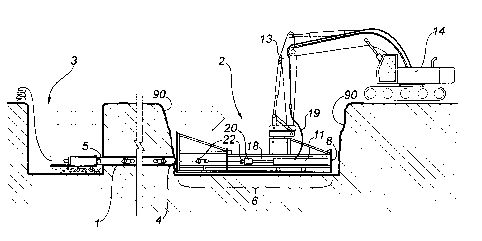
Figure 1 is a diagrammatic view of the one embodiment of the
21 present invention showing a pus~her/puller apparatus connected to the boom
of an
22 excavator. The apparatus is poised to pull old pipe out of the ground and
pull new
23 pipe in;
11
CA 02245479 2000-06-22
1 Figures 2a and 2.b are side views of the in-ground portion of the
2 pusher/puller apparatus. Fig. 2a details the reaction plate structure which
is shown
3 exploded from the actuator shown in Fig. 2b;
4 Figure 3a and 3b are top views of the in-ground portion of the
pusher/pulleraccording to Figs. 2a and 2b;
6 Figure 4 is an isometric view of the quick-attach coupling of the
7 pusher/puller apparatus. prior t~o engagement. The coupling locking means is
8 shown in exploded form;
9 Figure 5a~ is a top view of the quick-attach coupling of the
pusher/puller illustrating the coupling mount and swivel indexing holes;
11 Figure 5b is a side view of the coupling of Figure 5a illustrating the
12 indexing lever and thE~ boom part of the mount in phantom lines prior to
13 engagement;
14 Figure 6a is a bottom view of the boom mount of the quick-attach
coupling;
16 Figure 6b is a side view of the boom mount of Figure 6a;
17 Figures 7a - 7c illustrate the various operations which are performed
18 in quick succession due to the quick-attach coupling. More specifically,
Fig. 7a
19 illustrates use of the bucket to excavate the pits. Fig. 7b illustrates the
use of the
pusher/puller boom-stabilized within the pit for extracting old pipe. Lastly,
Fig. 7c
21 illustrates the use of a ripper tooth to rapidly extract loosened pipe from
the ground;
22 Figure 8 illustrates the pusher/puller apparatus of Fig. 1 in the
23 process of pushing the old pipe for loosening it prior to pulling;
12
CA 02245479 2000-06-22
1 Figure 9 is. an exploded cross-sectional view of the new pipe-insertion
2 pig and new double-bell~ed pipe;
3 Figure 10 illustrates the pusher/puller apparatus of Fig. 1 in the
4 process of extracting oldl pipe and installing new pipe; and
Figure 11 is a perspective view of a pipe with a cable grip and bar set
6 to urge the pipe through the ground.
7
8 DETAILED DESCRIPTION OF THE PREFERRED EMBODIMENT
9 Having reference to Fig. 1, a buried old pipe 1 is shown which
requires replacement. A first pipe-extraction pit 2 and a second pipe-
insertion pit
11 are located at spaced-apart locations along and to access the old pipe. The
old
12 pipe 1 is cut within the pipe extraction pit 2 to form a first end 4. The
pipe is cut in
13 the insertion pit 3 to form a second end 5.
14
Pusher/Puller6
16 A pipe-pusher/puller 6 is provided for loosening and extracting the
17 length of old pipe 1 from the extraction pit 2. The pusher/puller 6 is
attached to the
18 tool end 10 located at the distal E:nd of the articulated boom 13 of a
vehicle such as
19 a mobile excavator 14.
The boom 13, in a first mode, is laterally and vertically movable for
21 positioning and orienting the tool end 10 into and out of the pits 2,3 and
once
22 positioned, in a secondl mode, the boom 13 is rendered rigid for
substantially
23 arresting relative movement befiNeen the tool end 10 and the excavator 14.
The
13
CA 02245479 2000-06-22
1 boom is hydraulically operated and when the boom is not being physically
2 manipulated, the boom's articulated joints and tool end are rigid relative
to the
3 excavator proper. Typically, when arrested, the boom is rigid enough to
cause the
4 excavator to move when force is applied to the tool end, thus bringing the
excavator's weight to bear as resistance.
6 Preferably, the pusher/puller 6 is removably mounted to the tool end
7 10 with a quick-attach coupling 24 which permits the one vehicle 14 to be
used for
8 more than one purpose, namely to permit quick substitution of the
pusher/puller 6
9 with optional tool attachments such as a bucket 15 (Fig. 7a - used to dig
the pits
2,3) or the ripper tooth 16 (Fig. 7c - used to rapidly pull loosened old pipe
1 as
11 described later).
12 Referring ;also to (Figs. 2a, 2b, 3a and 3b, the pipe pusher/puller 6
13 comprises four main parts: a frame 7 having a pushing end 8 and a pulling
end 9;
14 one-half of the quick-attach coupling 24 atop the frame 7 for attaching the
frame to
the tool end of the boom 13; a power-unit or actuator 11 mounted within the
frame
16 7; and a detachable reaction plate structure 12 for positioning at either
of the
17 pushing or pulling ends 8,9. Only one reaction plate structure 12 is
provided so as
18 to minimize the overall assembled length of the pusher/puller 6 and thus
minimize
19 the required size of the extraction pit 2.
The motive power for extracting old pipe 1 is provided by the
21 pusher/puller's actuator 11. The actuator 11 comprises two 5 foot long, 6"
double-
22 acting hydraulic cylinders 17, each having a piston (not shown) driving a 2-
1/2" ram
23 18. The cylinder's rams 18 are powered through hydraulic coupling with the
14
CA 02245479 2000-06-22
1 excavator's hydraulic system 19. The ends of the two rams 18 are connected
to a
2 common abutment or ram plate 20.
3 In a pushiing mode, the ram plate 20 bears against the end of the old
4 pipe 1. Pushing is accomplished through extension of the rams 18. The full
fluid
area of the ram's piston is available to generate a large pushing force,
greater than
6 that available during pulling (reduced due to the ram's cross-section).
7 The ram ~>late 20 has an eyelet 25 for connection to a pulling cable
8 26 when in a pulling mode. Pulling is accomplished through retraction of the
rams
9 18. Pulling force is Less than pushing force due to the piston area loss by
the ram.
Pipe pushing and pulling reactive forces are conducted through the
11 ends of the cylinders 17 connected to the frame 7. The frame 7 conducts
reaction
12 forces into the reaction plate structure 12.
13 The reaction plate structure 12 comprises a load-supporting frame 27
14 having a bearing plate c'.8, for engaging the wall 63 of the pits 2,3 and a
mounting
end 29 having means for connection to the frame 7. A pair of spaced "L"-shaped
16 hooks 30 at the mountiing end 29 hook onto connection plates 31 at either
the
17 pushing and pulling ends 8,9 of the frame 7. Two, laterally spaced-apart
bolts 32
18 secure the bottom of the reaction plate structure 12 to the frame 7.
19 The frame 7 has <~ longitudinally-extending open bottom 33 partially
along its axis from the pulling end 9, so as to permit the frame 7 to lower
over and
21 straddle the old pipe 1 extending into the first extraction pit 2.
CA 02245479 2000-06-22
1 The Quick-Attach Coupling 22
2 The quick-attach c;oupling 22 has frame and boom mounts 23,24. As
3 shown in Fig. 4, in a dEaached condition, the frame mount 23 of the quick-
attach
4 coupling 22 is secured to the fraime 7 or pusher/puller 6. The boom mount 24
of the
quick-attach coupling 22 is secured to the tool end 10 of the boom 13. The
frame
6 mount 23 is formed as a female mount for connection with the complementary
male
7 boom mount 24.
8 The female frame mount 23 comprises a first base 35 connected to
9 the frame 7, an engagernent housing 36 and a swivel 37 therebetween.
Also shown in Fic,~s. 5a,5b,6a and 6b the engagement housing 36
11 comprises an engagement fulcrum 38 opposing a first angled pinch plate 39.
A
12 cavity 40 is formed between the fulcrum 38 and the first pinch plate 39 for
accepting
13 the male boom mount 24.
14 The male boom mount 24 comprises a second base 41 for
connection to the boom's tool end 10 and a protrusion 42 depending from the
16 second base 41. The protrusion 42 has a lip 43 and a second angled pinch
plate
17 44.
18 During connection (Fig. 4 and 5b), the protrusion 42 engages the
19 engagement housing 36. The first and second pinch plates 39,44 slidably
engage,
driving the protrusion's lip 43 laterally into tight engagement with the
housing's
21 fulcrum 38, thereby ensuring no relative movement between the male and
female
22 mounts 23,24.
16
CA 02245479 2000-06-22
1 The male and ff:male mounts 23,24 are locked together once
2 engaged. A pair of bolts or studs 45 engage matched slots 46 formed in the
first
3 and second bases, 35,41, and in the engagement housing 36 (Fig. 4). Upper
nuts
4 47 and lower nuts 48 sandwich and lock the protrusion 42 to the engagement
housing 36. A pin 49a extends upwardly from the protrusion's base 41. A ladder
6 bar 49b (having two rungs and four legs 50) is slipped over the pin with a
pair legs
7 50 engaging the sides of the upper nuts 47 to prevent nut rotation,
loosening and
8 accidental loss of the studs 45. Strengthening ribs 51 in the structure
forming the
9 engagement housing 36 similarly serve to engage and prevent rotation of the
stud's
lower nuts 48.
11 Illustrated best in Figs. 5a and 5b, the swivel 37 enables rotation
12 between the engagement housing 36 and the female mount base 35. While the
13 rotation is only in one plane (azimuthal), manipulation of the boom also
permits
14 pitch and roll to be adju;>ted. Complementary, facing and matched indexing
holes
60 (8 shown) are formecl in both the engagement housing 36 and the base 35. An
16 index locking pin 61, operated using a spring-biased locking lever 62,
engages and
17 disengages from the aligned index holes 60 to alternately lock or permit
free
18 rotation of the engagement housing 36 relative to the base 35. The spring-
bias
19 causes the pin 60 to engage alic,~ned and facing indexing holes. The
engagement
housing 36 rotates on a pivot 63.
21 In other words, when the indexing holes 60 are locked, the
22 pusher/puller6 cannot rotate relaitiveto the excavator's boom 13.
17
CA 02245479 2000-06-22
1 In short, the quick-attach coupling 22 enables rapid and secure
2 connection of the pusher/puller 6 and accessories 15,6,16 (Figs. 7a,7b and
7c
3 respectively) to the boom 13. Once locked, the quick-attach coupling
securely
4 holds the pusher/puller 6 against a twisting movement encompassing any of
azimuth, pitch or roll.
6 From the foregoing it will be understood that each of the tool end and
7 the frame have elements of the coupling secured thereto, the elements being
8 operative to detachably engage to lock the tool end and frame together.
9
Operation - Extraction Of Old Piipe
11 In a first embodiment of the method of the invention, in operation, the
12 bucket 15 is attached to the boom's tool end 10 (Fig. 7a). Pipe-extraction
and pipe-
13 insertion pits 2,3 are dud at each end of the old pipe 1 to expose the old
pipe. The
14 exposed pipe is cut. The excavated length of the extraction pit 2 is equal
to greater
than the combined length of the frame 7 and the reaction plate structure 12.
If
16 physical access about the extraction pit 2 is limited, the excavator 14 can
be
17 positioned atop any excavated soil about the periphery of the pit 2. If
access to one
18 side of the extraction pit 2 is blocked, the quick-attach coupling 22
enables full
19 independent 360 degree indexed rotation of the pusher/puller 6.
Accordingly, the
excavator 14 can be located anywhere about the pit 2. The index locking holes
60
21 and pin 61 lock the rotational po:>itioning of the pusher/puller 6.
18
CA 02245479 2000-06-22
1 Once the pits 2,3 are dug, the bucket 15 is then detached and the
2 pipe pusher/puller 6 is connected to the male mount 24 of the boom's tool
end 10.
3 The actuator 11 is connected to the excavator's hydraulic system 19 with
quick-
4 connect hose couplings. The boom 13 is manipulated to lower pusher/puller 6
into
the pipe-extraction pit 2.
6 Ground can adhere to old pipe over time and it may be necessary to
7 first dislodge or break the old pipe 1 free of the ground with the pusher
action of the
8 pusher/puller 6. If so requirE:d and as shown in Fig. 8, the reaction plate
9 structure 12 is attached .at the pushing end 8 of the frame 7. The
pusher/puller 6 is
placed into the pit 2 with the axis of the frame 7 substantially in-line with
the old
11 pipe 1. The frame's open bottom 33 straddles the old pipe's first end 4
with the ram
12 plate 20 movement or actuation placed into co-axial alignment with the old
pipe 1.
13 The bearing plate 28 of the reaction plate structure 12 bears against the
pit wall 90
14 opposite the first end 4 of the old pipe 1. The ram plate 20 engages the
pipe's first
end 4. Hydraulic pressure is applied to the cylinder 17, driving the rams 18
and ram
16 plate 20. The old pipe 1 is pushed away from the pusher/puller 6 and is
driven into
17 the soil, thereby loosening it.
18 Reaction forces are transmitted through the bearing face 28 into the
19 pit wall 90 opposing the old pipe. If the pit wall 90 is not square to the
bearing plate
28, then pushing reaction forces cause the pusher/puller 6 to try to twist
square.
21 The boom 13 acts to hold the pusher/puller 6 square to the pipe 1,
regardless of the
22 condition of the bearing pit wall 90, and without using shoring or bracing.
More
23 particularly, while the bearing plate absorbs axial reaction forces, the
boom 13
19
CA 02245479 2000-06-22
1 secures the pusher/puller 6 against twisting relative to the pit wall
(preventing
2 relative pitch/roll or azimuthal movement).
3 If the old pipe 1 is successfully loosened or was already loose, then
4 the pusher/puller 6 is configured for pulling (Fig. 1,10). The boom 13 lifts
the
pusher/puller6 free of the pit and the reaction structure 12 is attached to
the pulling
6 or ram plate end 9 of the frame 7.
7 Having reference to Fig. 9, the pulling cable 26 is installed in the old
8 pipe 1.
9 Initially, thin sectional rods (not shown) are progressively threaded
together and pushed through tlhe old pipe 1 until they protrude from the
pipe's
11 second end 5. One end of a light cable (not shown) is secured to the
protruding
12 rods at the old pipe's second ~snd 5. The rods and end of the light cable
are
13 pulled back through the pipe's first end 5. The heavier segmented "pulling"
cable
14 26 is attached to the other end of the light cable at the second pit 3. The
light
cable is pulled out of the otd pipe 1 for drawing the pulling cable 26 through
the
16 old pipe 1 and into the extraction pit 2. A winch is usually required to
pull the
17 heavy pulling cable 26.
18 When rigged for pulling mode (Figs. 7b, 10), the pusher/puller 6's
19 quick-attach coupling 22 is manipulated to swivel the movement of the
actuator 11
into alignment with the old pipE: 1. The swivel permits the excavator 14 to be
21 optimally positioned about the pit 2.
CA 02245479 2000-06-22
1 The pushe~r/puller 6 is lowered into the extraction pit 2 to straddle the
2 old pipe's first end 4. The pullirng cable 26 is connected to the eyelet 25
of the ram
3 plate 20 with a clevis and pin 22. Short choker cables or a link (not shown)
can be
4 used to make up any giap befinieen the end of the pulling cable 26 and the
ram
plate's eyelet 25.
6 At the second end 5 of the old pipe 1 in the insertion pit 3, a cable
7 grip 64 (Fig. 11 ) is slid along the pulling cable 26 to the end of the
pipe's second
8 end 5 to secure the pulling cable 26. Such a cable grip is available as
Klein
9 "Chicago"~ grips, available from Wire Rope Industries, Edmonton, Alberta.
The
cable grip 64 has an eyelet 65. A bar 66 is inserted through the grip's eyelet
65
11 and extends transversely to bear against the pipe's second end 5.
12 The rams 18 and ram plate 20 are actuated to retract and tighten the
13 pulling cable 26. Further retraction of the rams 18 pulls on the cable 26,
pulling the
14 bar 66 to abut against the pipe's second end 5 so as to push or force the
pipe 1 out
of the ground and into the extraction pit 2. For the specified rams 18, a
hydraulic
16 pressure of about 4000 pounds per square inch (psi) is maximum, greater
forces
17 usually causing unwanted deforrnation of the pin of the connecting clevis
22.
18 As the stroke of the rams 18 is exhausted, the cylinders are extended
19 and the grip 64 is re-gripped to slhorten the effective length of the
pulling cable. The
cycle of actuation and cable re-dripping is performed as often as necessary to
pull
21 the old pipe 1.
21
CA 02245479 2000-06-22
1 As was similarly alescribed for the pusher operation, pulling reaction
2 forces are transmitted through the bearing face 28 into the pit wall 90,
this time
3 adjacent the old pipe's first end 4. Once again, the boom 13 acts to hold
the
4 pusher/puller 6 against twisting, regardless of the condition of the bearing
pit wall
90, and without using shoring or bracing.
6 Typically, 'when the hydraulic pressure necessary to pull the old pipe
7 1 drops to about 1000 psi, the old pipe 1 is suitably loose enough to pull
it out with
8 the boom 13 alone. Accordingly, great savings in time can be achieved.
9 More specifically, when the pipe is suitably loose, the pusher/puller
6 is removed from the pit 2. Tlhe pusher/puller 6 is de-coupled from the
boom's
11 quick-attach coupling 2.2. Means are then provided to directly connect to
the
12 pulling end of the cable, such ass by a hook on the tool end of the boom or
more
13 preferably by quickly replacing 'the pusher/puller 6 and coupling a ripper
tooth 16
14 to the tool end 10. The end of the pulling cable 26 is hooked over the
ripper
tooth 16 and the boom 13 is used to pull the old pipe 1 out of the extraction
pit 2.
16 The boom has a long range of motion and rapidly pulls the pipe 1. Discrete
17 lengths of pulled old pipe 1 are removed from the pulling cable 26 as
necessary
18 and the cable is shortened for the next pulling stroke.
22
CA 02245479 2000-06-22
1 Operation - Simultaneous Insertion Of New Pipe
2 In a second embodiment of the method, new pipe 70 is inserted
3 while the old pipe 1 is a:~ctracted (Figs. 1 and 10).
4 Having reference also to Fig. 9, a pig 71 is utilized, placed at the
second end 5 of the olcl pipe 1. During the pulling process, the pulling cable
26
6 pulls the pig 71 which in turn pushes the old pipe 1. The pig 71 follows and
urges
7 the old pipe 1 out of the ground and simultaneously enlarges the bore
through the
8 ground as the pig 71 progresses.
9 The pig 71 pulls new pipe 70 simultaneously into the ground behind
the pig 71.
11 The pig 71 comprises a tube 72 having a leading end 73 and trailing
12 end 74. A transverse member o~r plate 75 extends across the pig's leading
end 73
13 and, at a minimum, is sized for bearing against the old pipe 1. Preferably
the
14 diameter of the pig 71 or the bearing plate 75 is sized to ream the ground
behind
the old pipe 1, forming a larger bore, and thereby aiding in installation of
same-
16 sized or larger diameter new pipe 70. A tongue 76 extends from the bearing
plate
17 75 for connection to the pulling cable 26 with a clevis and pin 22. The
pig's trailing
18 end 74 has a bore 77 which is suifficiently large to accept the new pipe
70.
19 A pulling plate 78 its installed within the bore of the trailing end 74 of
the pig 71. The pulling plate 74 has a tongue 79 for connection to a
installation
21 cable 80 for pulling new pipe 70, also with a clevis and pin 22. The
pulling plate 78
22 is axially and inwardly offset frorn the trailing end 74 of the pig 71 so
that the new
23 pipe 70 extends into thE: pig 71. The installation cable 80 is threaded
through a
23
CA 02245479 2000-06-22
1 length or lengths of new pipe 70. The cable grip 64 and bar 66 retain the
new pipe
2 70 in close relation with the pig 71. The cable grip 64 is set to ensure the
leading
3 end of the new pipe 70 does not come out of the pig's trailing end and thus
4 prevents the entry of debris. As each new pipe 70 enters the ground, the
cable grip
64 is released, another length of new pipe is added. The installation cable 80
is
6 threaded through the new pipe and the cable grip 64 and bar 66 are reset.
7 Despite the reaming action of the pig 71, the new pipe 70 is still
8 subjected to significant axial loads as it traverses the ground. Generally,
9 conventional male/female belted pipe can be damaged as a male spigot end
engages the bell end or bell. As ahown in Fig. 9, a bell 81 has a radially
diminishing
11 profile as it approaches 'the main tubular portion of the pipe 70.
Accordingly, when
12 a spigot 'bottoms' within a bell (the leading edge of the spigot contacts
the
13 diminishing profile of the bell) it: first imposes an axial load and then
is urged to
14 follow the profile radially inwardlly, imposing ever greater radial forces
sufficient to
blow the bell apart.
16 Accordingly female/female or double-belted pipe 82 is used as the
17 new pipe 70. An appropriately sized male/male nipple 83 is inserted between
18 adjacent double-belted pipe 82. The nipple 83 engages facing bell ends 81
of the
19 two new pipes 70. The diameter of the nipple 83 is obviously of a
complementary
diameter to sealaby fit into the bell ends 81 of the double-belted pipe 82.
Further,
21 the length of the nipple 83 is such that the bell end 81 of one length of
new pipe 70
22 will butt up against the bell 81 of the adjacent new pipe 70 before the
nipple 83 can
23 'bottom' out. Accordingly, the ;axial loads imposed during installation are
borne
24
CA 02245479 2000-06-22
1 axially by the bell/bell 81/81 contact and, neither the bell/bell contact
nor the
2 nipple/bell end contact 83/81 create damaging radial forces.
3 The abovE~ apparatus is capable of pulling old pipe and optionally
4 installing new pipe in its place:
~ despite the old pipe being initially stuck in the ground;
6 ~ with minimum disruption of the area surrounding the pits;
7 ~ with minimal access requirements about the periphery of the
8 extraction pit;
9 ~ with minimal e~;posure of personnel in the pits;
~ without: the need for shoring, bracing and the associated
11 di~culties in maintaining them in place and maintaining the pulling
12 apparatus square in the extraction pit and to the pipe being pulled;
13 ~ while, as soon as possible, maximizing the rate of removal of old
14 pipe as. the force needed to pull the pipe reduces;
~ while minimizing the risk of damage of the new pipe; and
16 ~ with an overall and significant increase of the rate at which old
17 pipe can be extracted and new pipe can be installed.