Note : Les descriptions sont présentées dans la langue officielle dans laquelle elles ont été soumises.
CA 02245855 1998-08-11
NS g 7 I 0167 ~
PGT
2 4 t~OY ~
METHOD AND APPARATUS USING GUIDE VANES FOR VAPOR
DISTRIBUTION IN MASS TRANSFER AND HEAT EXCHANGE COLUMNS
Background of the Invention
This invention relates in general to mass transfer and heat exchange
columns and, more particularly, to a method and apparatus to improve vapor
distribution
in such columns.
Vapor and liquid interaction is required in many types of mass transfer and
heat exchange processes. Typically, the vapor stream is introduced to a column
below
a region containing trays or a random or structured packing while the liquid
stream is
introduced into the column above the trays or packing. The vapor and liquid
streams then
flow in countercurrent relation through the region, with the tray or packing
serving to
distribute the downwardly flowing liquid stream over a larger surface area to
enhance the
interaction with the upwardly flowing vapor stream.
In order to increase the efficiency of the mass transfer or heat exchange
taking place between the vapor and liquid streams, it is important that the
vapor be
uniformly distributed across the horizontal cross-section of the column,
particularly at the
lower vapor-liquid interface where the vapor enters the packing. When the
vapor is
introduced to the column below the packing, the velocity of the vapor can
prevent the
desired horizontal distribution of the vapor prior to its entry into the
packing. In order
2 o to improve the vapor distribution, deflectors have been positioned in some
columns in
the flow path of the vapor to deflect the vapor in a plurality of directions.
One example
of such a deflector is a V-shaped deflector which is positioned at the vapor
inlet to split
the vapor stream into two streams flowing in opposite directions. This
deflector is of a
simple design and performs adequately in many installations that tolerate some
2 5 maldistribution of the vapor stream.
Another example of a conventional vapor distributor known as a vapor
horn is disclosed in U.S. Patent No. 5,106,544. The vapor horn disclosed in
that patent
comprises an annular housing which is open at the bottom. The vapor horn
contains a
plurality of vanes which extend upwardly at progressively greater distances
into the
3 o housing through the open bottom for causing downward deflection of the
circumferentially flowing vapor stream. The downwardly deflected vapor is then
said to
rise in a uniform manner into a packing bed which is positioned radially
inwardly from
the vapor horn.
~'-D ~
CA 02245855 1998-08-11 ~ j ~ ~ 6 7 $
i~~~u~ 2 4 Nov lit;
-2-
While conventional vapor distributors can function satisfactorily in many
applications, a need has arisen for an improved vapor distributor which will
provide a
more uniform distribution of vapor across the horizontal cross-section of a
mass transfer
or heat exchange column.
~ummarv of the Invention
It is a primary object of this invention to provide a vapor distributor which
is effective to increase the horizontal distribution of vapor entering a mass
transfer or heat
exchange column so that enhanced vapor and liquid interaction in the column
can be
achieved.
1 o It is another object of this invention to provide a vapor distributor
which
is of simple design so that it may be easily installed in a column and yet
provides uniform
horizontal distribution of vapor entering the column.
To accomplish these and other related objects, in one aspect the invention
is directed to a mass transfer or heat exchange column comprising: a shell
presenting an
open internal volume and having a generally vertical center axis;. a vapor
inlet nozzle
extending through said shell for directing a vapor stream into said open
internal volume
in a generally radial direction; a distributor within said shell and
comprising a generally
upright deflecting surface spaced radially inwardly from the vapor inlet
nozzle and top
and bottom plates extending between the deflecting surface and the shell to
substantially
2 0 close the top and bottom of the distributor, said deflecting surface being
shaped and
positioned in relation to said vapor inlet nozzle to divide and redirect the
vapor stream
from said generally radial direction to oppositely directed flow paths about
an inner
periphery of the column shell; and guide vanes within said shell and
positioned in said
vapor stream flow paths in spaced relationship from the distributor to
redirect at least a
2 5 portion of said vapor stream toward said center axis from said flow paths
about the inner
periphery of the column shell to cause a more uniform distribution of the
vapor stream
across a horizontal cross section of the column.
In another aspect, the invention is directed to a method for distributing a
vapor stream within a mass transfer or heat exchange column having an external
shell and
3 o a vapor inlet nozzle extending through said shell, said method comprising
the steps of
providing a distributor within the external shell of said column, said
distributor
k~,-~~~'fl ~tt~~
CA 02245855 1998-08-11
WO 97/28893 PCT/LTS97101678
-3-
comprising a generally upright deflecting surface spaced radially inwardly
from the vapor
inlet nozzle and top and bottom plates extending between the deflecting
surface and the
shell to substantially close the top and bottom of the distributor;
introducing the vapor
stream into the distributor through the vapor inlet nozzle and directing the
vapor stream
' S against the deflecting surface to divide and redirect the vapor stream to
oppositely
directed flow paths about an inner periphery of the column shell as it is
discharged from
the distributor; and then contacting the vapor stream against guide vanes
spaced from the
distributor in said oppositely directed flow paths to redirect at least a
portion of said
vapor stream toward said center axis from said flow paths to cause a more
uniform
distribution of the vapor stream across a horizontal cross section of the
column.
Brief Description of the Drawings
In the accompanying drawings which form a part of the specification and
are to be read in conjunction therewith and in which like reference numerals
are used to
indicate like parts in the various views:
Fig. 1 is a fragmentary side elevation view of a column in accordance with
the present invention showing a vapor inlet nozzle and a vapor distributor and
a packing
zone which are illustrated by broken lines;
Fig. 2 is an enlarged top plan view of the column and vapor distributor
taken in horizontal section along line 2-2 of Fig. 1 in the direction of the
arrows, the
2 0 direction of flow of the vapor through the distributor being illustrated
by arrows;
Fig. 3 is a side elevation view of the column and vapor distributor taken
in vertical section along line 3-3 of Fig. 2 in the direction of the arrows;
Fig. 4 is a fragmentary top plan view of an end portion of an alternate
embodiment of a vapor distributor of the present invention;
2 5 Fig. 5 is a top plan view of another embodiment of a vapor distributor,
portions being broken away to illustrate the open bottom of the distributor;
Fig. 6 is a fragmentary elevation view of the vapor distributor shown in
Fig. 5 and taken in vertical section along line 6-6 of Fig. 5 in the direction
of the arrows;
' Fig. 7 is a fragmentary side elevation view of the vapor distributor shown
3 o in Fig. 5 and taken in vertical section along line 7-7 of Fig. 5 in the
direction of the
arrows, portions being broken away to show the open bottom of the distributor;
CA 02245855 1998-08-11
WO 97!28893 PCT/1JS97/01678
-4-
Fig. 8 is a fragmentary top plan view of still another embodiment of a
vapor distributor of the present invention, portions being broken away to
illustrate details
of construction;
Fig. 9 is a fragmentary side elevation view of the vapor distributor shown
in Fig. 8 and taken in vertical section along line 9-9 of Fig. 8 in the
direction of the
arrows, portions of an inner wall of the distributor being broken away for
purposes of
illustration;
Fig. 10 is a fragmentary top plan view of a further embodiment of a vapor
distributor with portions broken away to illustrate details of construction;
1 o Fig. I 1 is a fragmentary side elevation view of the vapor distributor
shown
in Fig. I O and taken along Line 1 I-I I of Fig. 10 in the direction of the
arrows;
Fig. 12 is a fragmentary top plan view of a still further embodiment of a
vapor distributor of the present invention, portions being broken away to
shown the open
bottom of the distributor;
Fig. 13 is a fragmentary side elevation view of the vapor distributor shown
in Fig. i2 and taken in vertical section along line I3-13 of Fig. 12 in the
direction of the
arrows;
Fig. 14 is a fragmentary elevation view of the vapor distributor shown in
Fig. I2 and taken in vertical section along line 14-I4 of Fig. 12 in the
direction of the
2 0 arrows;
Fig. 15 is a fragmentary side elevation view of a column similar to that
shown in Fig. I but showing an alternate embodiment of a vapor distributor of
the present
invention;
Fig. 16 is an enlarged top plan view of the column shown in Fig. 15 taken
in horizontal section along line 16-16 of Fig. 15 in the direction of the
arrows, the
direction of vapor flow being indicated by arrows;
Fig. 17 is a fragmentary side elevation view of the column shown in Fig.
15 taken in vertical section along line I 7-17 of Fig. 16 in the direction of
the arrows, and
showing the deflector positioned in relation to the vapor inlet;
3 0 Fig. 18 is a fragmentary, side elevation view of the column taken in
vertical section showing au alternate embodiment of a guide vane; and
CA 02245855 1998-08-11
WO 97/28893 PCTlUS97/01678
-S-
Fig. 19 is a top plan view of a column taken in horizontal section and
showing an alternate embodiment of the invention shown in Fig. 15.
_ Description of the Preferred Embodiments
Turning now to the drawings in greater detail, and initially to Figs. 1-3,
' 5 a column constructed according to a first embodiment of the present
invention is
represented by the numeral 20. Column 20 comprises a rigid exterior shell 22
which is
of cylindrical construction and presents an open internal volume through which
fluid
streams may flow. The column shell 22 can also be of other desired
configurations
including those which are of square, rectangular or other polygonal cross
section. The
1 o column 20 can be a mass transfer andlor heat transfer column, depending
upon the types
of chemical processing operations which are to be performed within column 20.
Column 20 includes a zone 24 in which trays or packing are positioned
to facilitate interaction between liquid and vapor streams flowing through the
open
internal volume of the column. The packing can be random or structured packing
and
15 multiple zones of such packing and/or trays can be provided. It wilt be
appreciated that
the column 20 can include reboilers, reflux lines and other components which
are
necessary or desired for the particular chemical processing being conducted
within the
column.
The column 20 also includes a vapor horn or distributor 26 constructed
2 0 in accordance with the present invention to facilitate a more uniform
distribution of vapor
as it flows upwardly and enters packing zone 24. It will be appreciated that
liquid can
be and usually is associated with the vapor and the use of the term "vapor" is
intended to
encompass the presence of liquid. The vapor distributor 26 is positioned in a
plane
beneath the trays or packing in zone 24 and is in communication with a radial
inlet nozzle
2 5 28 which extends through the column shell 22 to allow the introduction of
vapor into the
column 20 in a direction generally perpendicular to the column shell. As can
best be seen
in Fig. 2, the distributor 26 includes an inner annular wall 30 which is
spaced radially
inwardly from the column shell 22 in the same general horizontal plane as the
inlet nozzle
28. The annular wall 30 and column shell 22 form the sides of an annular
pienum 32
3 0 which provides a vapor flow path around the inner circumference of the
column shell 22.
As is shown in Fig. 3, the plenum 32 is generally rectilinear and is closed
CA 02245855 1998-08-11
WO 97/28893 PCT/US97/01678
-6-
at the top by a ring-shaped top plate 34 which extends horizontally between
the inner
annular wall 30 and the column shell 22. A ring-shaped bottom plate 36 closes
the
bottom of the plenum 32 and likewise extends between the inner annular wall 30
and
column shell 22. The top and bottom plates 34 and 36 are secured to the inner
annular
wall 30 in a suitable manner such as by welding and can be secured to the
inner surface
of the column shell 22 in a similar manner. The inner annular wall 30 and
plates 34 and
36 can be constructed of various suitable materials which are sufficiently
rigid to
withstand the pressures exerted by the vapor stream flowing through plenum 32.
The
material selected should also be compatible with and be resistant to
degradation by the
l0 vapor and Liquid encountered within the column 20.
Returning to Fig. 2, the inner annular wall 30 comprises a plurality of
circumferentially extending segments 38a, 38b and 38c which are radially
staggered to
form outlet ports 40 along the circumference of the annular wall 30. Each
outlet port 40
allows a portion of the vapor stream flowing in plenum 32 to be directed
through the
outlet port 40 and into the open area of column 20 located radially inward
from the
annular wall 30. The use of a plurality of the outlet ports 40 allows the
vapor stream in
plenum 32 to be divided into a number of smaller individual streams which are
directed
from the plenum at spaced apart locations. The division of the vapor stream in
this
manner allows for turbulent mixing of the vapor streams in the open area,
which in turn
2 o results in a more uniform distribution of the vapor across the horizontal
cross section of
the column 20 than could be achieved if the vapor were simply allowed to pass
into the
column interior directly from the vapor inlet nozzle 28.
The inner annular wall segments 38a, 38b and 38c are generally concentric
with the column shell 22 but each segment is radially offset from the adjacent
segment
2 5 so that the width of the plenum 32 becomes progressively more restricted
in the direction
of flow of the vapor stream. The wall segment 38a is located at the vapor
inlet nozzle 28
and serves to divide the vapor stream entering the column 20 through nozzle 28
into two
streams flowing circumferentialiy in opposite directions within plenum 32. The
wall
segments 38b located adjacent and downstream from the wall segment 38a are
spaced
3 0 radially outward from the wall segment 3 8a and overlap the ends thereof
to form the sides
CA 02245855 1998-08-11
WO 97!28893 PCT/US97I01678
of the outlet ports 40. Similarly, the wall segments 38c overlap the ends of
wall segments
38b and are spaced more closely to the column shell 22 than wall segments 38b.
At the downstream end of the wall segments 38c, the outlet ports 40 are
formed by the spacing between the wall segments 38c and the column shell 22.
The
~ 5 downstream end of wall segments 38c and the corresponding outlet ports 40
are located
approximately 180 ° from the vapor inlet nozzle 28, although other
locations are possible
and may be preferred in some applications. A deflector 42 is mounted to the
column
shell 22 at a position between the outlet ports 40 at the downstream end of
the wall
segments 38c so that the vapor discharge from such ports is deflected radially
inwardly.
Z 0 Although the deflector 42 is shown as being of planar construction, it
will be appreciated
that curvilinear surfaces could be provided if desired. In addition, the
downstream ends
of the wall segments 38c could be flared radially inwardly to increase the
cross-sectional
area of the associated outlet ports 40 as shown in Fig. 4.
Because the width of the outlet ports 40 corresponds to the radial spacing
15 of wall segments 38a, 38b and 38c, it will be apparent that the quantity of
vapor passing
through each port 40 can be predetermined by positioning the wall segments at
the
desired radial locations. Preferably, each port 40 has approximately the same
cross-
sectional area so that the vapor stream flowing in the plenum 32 is evenly
divided among
the outlet ports 40 and the velocity of the vapor stream exiting each outlet
port 40 is
2 o substantially the same. It can be appreciated that splitting the vapor
stream in this fashion
allows it to enter the open interior volume of the column 20 in a more uniform
manner.
The number of outlet ports 40 can also be varied from that shown by increasing
or
decreasing the number of segments of the inner annular wall 30. In general,
increasing
the number of outlet ports 40 causes a more uniform distribution of the vapor
stream
25 within the column interior. The quantity of vapor exiting each port 40 can
also be
controlled by varying the distance of overlap of the wall segments 38a, 38b
and 38c at
each port 40.
The outlet ports 40 discharge the multiple vapor streams in a
circumferential direction within a common horizontal plane. If desired, a
curved
3 o deflector 44 can be positioned within a portion of the vapor discharge
stream adjacent one
or more outlet ports 40 to deflect a portion of the stream in a different flow
direction and
CA 02245855 1998-08-11 -
w~~I~a~~~t
24
_g_
increase the distribution of the vapor. However, in many applications,
sufficient vapor
distribution can be achieved without the use of deflectors 44.
It can be readily seen that the vapor distributor 26 serves to distribute the
vapor stream entering the column 20. In a process in accordance with the
present
invention, a vapor stream is introduced into the column 20 through vapor inlet
nozzle 28
and enters vapor distributor plenum 32. The vapor stream flows in the plenum
32 around
the inner periphery of the column 20 and is split into a plurality of smaller
streams which
are distributed into the column interior by outlet ports 40. The distributed
vapor streams
then ascend in the open interior volume of the column 20 and feed into the
packing zone
24 positioned above the vapor distributor 26. The vapor entering the packing
zone 24
,: encounters and interacts with a liquid stream which has been introduced
into the column
at a location above the packing zone 24. Notably, because the vapor entering
the packing
zone 24 has been uniformly distributed across the horizontal cross-section of
column 20,
interaction between the vapor and liquid in the packing zone 24 is greatly
facilitated,
particularly in the lower portions of the packing.
It can be appreciated that other modifications of the vapor distributors
previously described can be made and remain within the scope of the invention.
As but
one example, the ring-shaped bottom plate can be removed from the described
embodiments of the vapor distributor. This allows portions of the vapor stream
to flow
2 o downwardly out of the plenum through the open bottom while other portions
flow
-.
radially inwardly through the outlet ports in the inner annular wall of the
vapor
distributor.
Further embodiments of the vapor distributor of the present invention are
illustrated in Figs. 5-14, in.which the same reference numerals preceded by
the prefix "1"
2 5 are used to designate components which have been previously described.
Turning first to Fig. 5, an alternate embodiment of a column constructed
in accordance with the present invention is designated by the numeral 120.
Column 120
differs from column 20 in one aspect by utilizing a tangential vapor inlet 128
instead of
the radial inlet nozzle 28 used with column 20. Because the vapor stream
enters the
3 0 plenum 132 tangentially to the column shell 122, it is not split into two
streams flowing
in opposite directions, as is the case with column 20. Instead, the plenum 132
carries the
vapor stream in only one direction about the inner_periphery of the column
shell 122.
CA 02245855 1998-08-11
WO 97/28893 PCT/US97/01678
-9-
The plenum 132 in column 120 extends substantially 360 ° about the
inner
periphery of the column shell 122. Although the initial inner annular wall
segment 138a
adjacent the vapor inlet nozzle 128 has been illustrated as being of planar
construction,
it could alternately be of a curvilinear configuration.
Distributors 126 differ from those previous described in that they have an
at least partially open bottom through which all or substantially all of the
vapor is
discharged. A uniform discharge of the vapor through the open bottom of the
distributor
126 is obtained by providing within the distributor a conduit or flow channel
142 having
a decreasing cross-sectional area in the direction of vapor flow. As portions
of the vapor
stream are discharged through the bottom of the distributor 126, the
decreasing area of
the flow channel 142 serves to maintain the vapor remaining within the flow
channel at
the desired pressure. By maintaining the desired pressure on the vapor stream
in this
manner, the quantity of vapor discharged along the annular length of the
distributor
remains substantially uniform and results in more uniform distribution of the
vapor
stream across the horizontal cross section of the column 120.
The flow channel 142 can be square, rectilinear, polygonal, round or oval
in vertical cross section. As illustrated in Figs. 5-14, the annular flow
channel 142 is
rectilinear in cross section and is defined by the top plate 134, inner
annular wall 130 and
the column shell 122. Although shown with the bottom completely open, it will
be
2 o appreciated that the flow channel 142 can be partially closed at the
bottom if desired.
The decreasing vertical cross section of the flow channel 142 is achieved
by placement of the inner annular wall I30 more closely to the column shell
122 in the
direction of vapor flow. In each of the embodiments shown in Figs. 5-14, the
inner
annular wall 130 is segmented with the segments being concentric with the
column shell
2 5 122 and placed progressively closer to shell 122 in the direction of vapor
flow. The
cross-sectional area of the distributor 126 thus decreases in a step-wise
manner in the
direction of vapor flow. The number of wall segments utilized can vary as
desired.
Alternatively, the inner annular wall 130 can extend in a continuous curve so
that the
narrowing of the flow channel 142 is continuous rather than step-wise.
3 0 When the inner annular wall 130 is formed by concentric segments as in
the distributors shown in Figs. 5-14, an upright deflector wall 144 is placed
at the
CA 02245855 1998-08-11
WO 97/28893 PCT/US97101678
-10-
downstream end of each inner annular wall segment and is connected to the
upstream end
of the next inner annular wall segment. Another deflector wall 144a is also
positioned
at the downstream end of the final annular wall segment and is joined to the
column shell
I22 to close the end of the vapor flow channel 142.
The deflector walls 144 not only form the transition between the inner
annular wall 130 segments, but also serve to disrupt and deflect the flow of
that portion
of the vapor stream traveling in the flow channel 142 adjacent to the inner
annular wall
130. The deflection of the vapor stream in this manner causes an increase in
the
turbulence and the resulting mixing of the entire vapor stream flowing within
the flow
channel 142. A portion of the deflected vapor stream is also directly funneled
out of the
open bottom of the distributor 126 by the deflector walls 144. The vapor
stream is thus
discharged from the distributor 126 by both the increase in flow resistance as
it travels
through the constricting flow channel 142 and the deflector walls 144 which
interrupt the
flow of portions of the vapor stream.
The deflector walls 144 can be oriented in various ways depending upon
the particular flow pattern desired. As shown in Figs. 5-7, each deflector
wall 144 can
be positioned to Iie along a radial line. The radial deflector walls 144 thus
extend
generally perpendicular to the inner annular wall and parallel to the vertical
axis of the
column 120.
2 0 Alternatively, as shown in Figs. 8 and 9, the radial deflector walls i 44
can
be inclined at an angle to the vertical axis of column I20 in the direction of
flow of the
vapor stream. inclination of the deflector walls 144 in this manner increases
the
downward deflection of the vapor stream in comparison to the vertically
oriented
deflector walls 144 and more efficiently funnels portions of the vapor stream
downwardly
and out of the bottom of the distributor 126. It will be appreciated that the
angle of
inclination can vary from that illustrated and remain within the scope of the
invention.
Another variation of the orientation of the deflector walls 144 is shown
in Figs. 10 and I l, wherein the deflector walls are vertical but are angled
with respect to
the radial line or radius of the column 120. The angled deflector walls 144
provide a
3 o smoother transition between the inner annular wall 130 segments in
comparison to the
CA 02245855 1998-08-11
WO 97/28893 PCTlUS97/01678
-11-
radial deflector walls and are less disruptive to the flow of the vapor
stream. As a result,
the vapor stream is preferentially funneled radially outward rather than
downwardly.
A still further variation of the orientation of the deflector walls I44 is
shown in Figs. 12-14, with the deflector walls 144 extending at an angle to
both the
column vertical axis and the radial line. The angled deflector walls 144 thus
serve to
preferentially funnel portions of the vapor stream downwardly and radially
outwardly at
the same time.
The distributors 126 shown in Figs. 5-14 can be operated in a manner
similar to the distributors previously described to cause a uniform
distribution of a vapor
I 0 stream entering column 120 through inlet nozzle 128. In order to allow the
volumetric
flow rate of vapor exiting the open bottom of the distributor 126 to remain
substantially
uniform along the length of the distributor, the amount by which the area of
the flow
channel 142 decreases along its length is selected in conjunction with the
volumetric
vapor flow rates, inlet vapor pressure and temperature, specific gravity of
the vapor, and
length of the flow channel.
'The pressure differential between the vapor flowing in the distributor I26
and in adjacent areas of the column 120 causes portions of the vapor stream to
flow out
the open bottom of the distributor. By decreasing the area available within
the distributor
126 for the flow of the vapor stream as it travels along the flow channel I42,
a more
2 o controlled pressure differential is maintained along the length of the
distributor. This
then results in a more uniform discharge of the vapor stream along the annular
length of
the distributor, with the discharged vapor stream being more uniformly
distributed across
the horizontal cross section of the column 120 prior to entry into the
overlying packing.
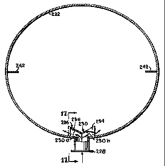
Turning now to Figs. 1 S-18, where reference numerals with the prefix "2"
2 5 are used to designate like components previously described, a column 220
is shown
which incorporates a distributor 226 which extends about only a minor portion
of the
inner radius or periphery of a shell 222 of the column 220. The distributor
226 includes
a deflecting surface 230 which is positioned radially inwardly at the vapor
inlet nozzle
228 so that the radially directed vapor stream entering the column through the
nozzle is
3 o brought into contact with the deflecting surface. The deflecting surface
230 is shaped and
positioned to divide the vapor stream and redirect it in oppositely directed
flow paths
CA 02245855 1998-08-11
WO 97/28893 PCT/US97/01678
-I2-
about the inner periphery of the column shell 222. The deflecting surface 230
is
preferably V-shaped when viewed from above to present two generally upright
impingement surfaces 230a and 230b that face away from each other and
intersect along
a vertical line near the nozzle 228. The included angle formed by the
intersecting
impingement surfaces 230a and 230b can be vary as desired. In general the
included '
angle will range from approximately 30 ° to 180 °, and more
preferably from
approximately 90 ° to 150 °. Alternatively, deflecting surface
230 can be formed by more
than two planar impingement surfaces or an outwardly convex arcuate surface.
The
deflecting surface 230 may also be inclined downwardly at an angle to the
vertical so that
1 o the vapor stream is deflected at a downward angle while it is being
deflected
circumferentially. The angle of deflection can be varied as desired, such as
between an
angle of 0 ° and approximately 30 °, and more preferably at an
angle between
approximately 0 ° and I S °.
The distributor 226 also includes a top plate 234 and a bottom plate 236
which extend between the deflecting surface 230 and the shell 222 to
completely or at
least substantially close the top and bottom of the distributor. One or both
of the top plate
234 and the bottom plate 236 can extend generally horizontally or can be
inclined
downwardly from a radial mid-line to present opposed downwardly sloping
portions in
the direction of vapor discharge from the distributor 226. Preferably, both
the top and
2 o bottom plates are downwardly inclined from the radial mid-line at the same
angle, which
angle may range from 0 ° to approximately 3 0 ° and more
preferably is approximately
10°. The sides of the distributor 226 remain open to permit the
discharge of the vapor
stream in oppositely directed flow paths about the inner periphery of the
column shell
222. In certain applications, the bottom plate 236 andlor the top plate 234
may be
omitted. More typically, however, only the bottom plate 236 would be omitted.
The distributor 226 is positioned to cover the inlet nozzle 228 and is sized
to extend along a portion of the periphery of the shell 222. The peripheral
dimension of
the distributor 226 can range from approximately the width of the nozzle 228
opening to
slightly less than the circumference of the shell 222. Desirably, the
peripheral dimension
3 0 of the distributor 226 is less than one-half of shell circumference and
preferably is less
than one-quarter of the circumference.
CA 02245855 1998-08-11
WO 97/28893 PCTIUS97/01678
-13-
Guide vanes 242 which rnay be similar to deflector 42 previously
described are positioned at locations circumferentially spaced from the
distributor 226.
The guide vanes 242 are located within the flow path of the vapor stream
discharged from
the distributor 226 and desirably are of a vertical height such that the top
and bottom
edges of at Least one vane in each flow path lie in horizontal planes above
the top and
bottom edges, respectively, of the distributor 226. More than one guide vane
242 may
also be positioned within each flow path. If a plurality of guide vanes 242
are used, they
should be of progressively larger size in a downstream direction. The shape of
the guide
vanes 242 can also be varied as desired. In the illustrated embodiment, the
guide vanes
are generally planar and are radially aligned. 'The guide vanes 242 could also
be arcuate
or any suitable shape for redirecting the vapor stream toward the central
vertical axis of
the column. The guide vanes 242 need not be radially aligned but could be
tilted or
angled much like the deflector walls 144 previously described. In addition,
the guide
vanes 242 can be positioned against an inner surface of said column shell 222
to block
35 the flow of the vapor stream along said inner periphery of the shell
between the guide
vanes and inner surface. Alternatively, the guide vanes 242 can be spaced from
the inner
surface of said shell 222 as shown in Fig. 18 to permit a portion of said
vapor stream to
flow between the spaced guide vane and the inner surface of the shell 222. It
will be
appreciated that the width of the guide vanes 242 in the radial direction can
be varied as
2 0 desired.
The circumferential positioning of the guide vanes 242 can be selected a.s
desired for particular applications. Desirably, the guide vanes 242 in the
oppositely
directed flow paths are positioned equidistance from the distributor 226. It
has been
found that a uniform distribution of the vapor stream across the horizontal
cross section
2 5 of the column can be achieved by placing the guide vanes 242 at positions
180 ° opposite
from each other and equidistant from the distributor 226. Other suitable
placements are
possible and are within the scope of the invention.
In operation, distributor 226 functions in a manner similar to distributor
' 26 previously described except the vapor stream is free to flow a much
greater distance
3 0 about the inner periphery of the shell 222 unconstrained by the
distributor 226.
CA 02245855 1998-08-11
WO 97/28893 PCT/US97/01678
-14-
It will be appreciated that more than one vapor inlet nozzle 228 may be
utilized in the column. Such an arrangement is illustrated in Fig. 19 where
two inlet
nozzles 228 and two associated distributors 226 are illustrated. The inlet
nozzles 228 are
positioned directly opposite from each other but they may be placed closer
together if
desired. One or more guide vanes 242 are positioned intermediate the opposed
distributors 226 to deflect the circumferential vapor streams toward the
vertical center
axis of the column. In the illustrated embodiment, two guide vanes 242 are
positioned
along the shell 222 in both circumferential directions and are spaced
equidistance from
each other and the adjacent distributor 226. This spacing, as well as the
number of guide
l0 vanes 242, can be varied as desired.
From the foregoing, it will be seen that this invention is one well adapted
to attain alI the ends and objects hereinabove set forth together with other
advantages
which are inherent to the structure.
It will be understood that certain features and subcombinations are of
25 utility and may be employed without reference to other features and
subcombinations.
This is contemplated by and is within the scope of the claims.
Since many possible embodiments may be made of the invention without
departing from the scope thereof, it is to be understood that all matter
herein set forth or
shown in the accompanying drawings is to be interpreted as illustrative and
not in a
limiting sense.