Note : Les descriptions sont présentées dans la langue officielle dans laquelle elles ont été soumises.
CA 02247260 1998-08-24
W O 97/32134 PCTrUS97/03004
POWER ST~RING SYSTEM Wll'H A VARIABLE BL~S E~ I w~r~ VALVE ELEMENTS
Backqround of the Invention
The present invention relates to a vehicle power
steering system and more specifically to a vehicle power
steering system in which the resistance to actuation of a
power steering motor control valve is varied.
A known vehicle power steering system is disclosed in
U.S. Patent No. 4,~19,545. The power steering system
disclosed in this patent includes a control valve assembly
having a resistance to actuation which increases as vehicle
speed increases. A speed responsive control unit is
connected in fluid communication with a pres~ure responsive
control unit in the valve assembly. The construction of
this known power steering system would be simplified if the
speed responsive control unit was eliminated.
Summary of the Invention
The present invention provides a new and improved
apparatus for use in a vehicle to control a flow of fluid
~ to a power steering motor. The apparatus includes motor
control valve members which are rotatable relative to each
CA 02247260 1998-08-24
WO97/32134 - PCT~S97/03004
other to control fluid flow from a pump to a power steering
motor. A biasing assembly resists relative rotation
between the motor control valve members.
The biasing assembly includes a pressure chA~hPr and a
force transmitting assembly. The pressure chamber is
operable under the influence of fluid pressure to actuate
the force transmitting assembly. The pressure chamber is
vented through a secondary valve which is operable in
response to relative rotation between the motor control
valve members.
The pump which supplies fluid to the motor control
valve members and to the pressure chamber is of the type
which supplies fluid at a high fluid flow rate during
operation of the pump at a low speed and supplies fluid at
a low fluid flow rate during operation of the pump at a
high speed. During operation of the pump at the low speed,
an orifice in the secondary valve assembly is effective to
restrict fluid flow to enable the fluid pressure in the
pressure chamber to increase. The increased fluid pressure
in the pressure chamber effects operation of the force
transmitting assembly to reduce the resistance to relative
rotation between the motor control valve members upon the
occurrence of relative rotation between the motor control
valve members.
During operation of the pump at a high speed, the
orifice in the secondary valve assembly is ineffective to
restrict fluid flow sufficiently to effect an increase the
CA 02247260 1998-08-24
W O 97132134 PCTrUS97/03004
--3--
fluid pressure in the pressure chamber. As a result, the
force transmitting assembly is not fully actuated to reduce
the resistance to relative rotation between the motor
control valve members. Therefore, the resistance to
relative rotation between the motor control valve members
during operation of the pump at a high speed is greater
than the resistance to relative rotation between the motor
control valve members during operation of the pump at a low
speed.
Brief DescriPtion of the Drawin~
The foregoing and other features of the present
invention will become more apparent upon a consideration o~
the following description taken in connection with the
accompanying drawings, wherein:
Fig. 1 is a sectional view of a power steering control
valve which is used in a vehicle to control a flow of fluid
to a power steering motor;
Fig. 2 is an enlarged fragmentary sectional view of a
portion of Fig. l; and
Fig. 3 is an enlarged schematic illustration depicting
the manner in which a secondary valve assembly vents fluid
pressure in the power steering control valve of Fig. 1.
Description of One Specific
Preferred Embodiment of the Invention
Power Steerinq S~tem - General DescriPtion
A vehicle power steerin~ system 12 (Fig. 1) is
operable to turn steerable vehicle wheels upon rotation of
CA 02247260 1998-08-24
W O 97/32134 PCT~US97/03004
a steering wheel by an operator of the vehicle. Rotation
of the steering wheel actuates a power steering control
valve 22 to port fluid from an engine driven pump 24 and
supply conduit 26 to either one of a pair of motor conduits
28 and 30. The high pressure fluid conducted from the
supply conduit 26 through one of the motor conduits 28 or
30 effects operation of a power steering motor 31 to turn
the steerable vehicle wheels. Fluid is conducted from the
motor 31 to a reservoir 32 throuqh the other one of the
motor conduits 28 or 30, the power steering control valve
22, and a return conduit 34.
The pump 24 is of the well known drooper type. The
pump 24 supplies fluid to the power steering control valve
22 at a high fluid flow rate when the pump is being driven
at a relatively low speed by the engine of the vehicle.
The pump 24 supplies fluid to the power steering control
valve 22 at a low fluid flow rate when the pump is being
driven at a relatively high speed by the engine of the
vehicle. Thus, the fluid flow from the pump 24 is a
maximum when engine of the vehicle is idlinq and the
vehicle is stationary. The fluid flow from the pump 24
decreases as vehicle speed increases. Pump having a
drooper type construction are disclosed in U.S. Patent Nos.
2,835,201; 3,349,714; and 4,681,517. Of course there are
other known pumps having a drooper type construction.
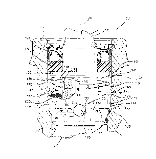
The power steering control valve 22 includes an inner
motor control valve ~her 40 and an outer motor control
CA 02247260 1998-08-24
W O 97/32134 PCTrUS97/03004
_5_
valve member or sleeve 42. The outer motor control valve
member 42 is cylindrical and encloses the inner motor
control valve member 40. The inner motor control valve
member 40 and outer motor control valve member 42 are
rotatable relative to each other and to a housing 44 about
a common central axis 46.
The inner valve member 40 is formed as one piece with
a cylindrical input member or valve stem 50 which is
connected with the steering wheel. The one piece outer
valve member 42 is connected with a follow-up member 54 by
a pin 56. The follow-up member 54 is rotatably supported
in the housing 44 by bearings 58 and 60. The follow-up
member 54 also provides a pinion gear 64 which is disposed
in meshing engagement with a rack 66. The rack 66 is
connected with the power steering motor 31 and steerable
vehicle wheels.
The power steering control valve 22 (Fig. 1) is of the
open center type. Therefore, when the power steering
control valve is in an initial or unactuated condition,
fluid pressure from the pump 24 is conducted through the
motor conduits 28 and 30 to motor cylinder chambers 72 and
74 on opposite sides of a piston 76 in the power steering
motor 31. Also, fluid flow from the pump 24 is directed by
the power steering contro~ valve 22 to the return conduit
34 and reservoir 32.
Upon rotation of the steering wheel and rotation of
the valve stem ~0, the inner valve member 40 is rotated
CA 02247260 1998-08-24
WO97/32134 PCT~S97/03004
--6--
about the axis 46, relative to the housing 44 and outer
valve member 42. This directs high pressure fluid from the
pump 24 to one of the motor conduits 28 or 30 and directs
fluid from the other motor conduit to the reservoir 32.
For example, rotation of the inner valve member 40 in
one direction relative to the outer valve member 42 will
reduce the extent of communication of the motor conduit 28
with the reservoir 32 and increase the extent of
communication of the motor conduit 28 with the pump 24.
This results in high pressure fluid from the pump 24 being
conducted to the motor cylinder chamber 72. This high
pressure fluid moves the piston 76 toward the right (as
viewed in Fig. 1). As the piston 76 moves toward the right
~as viewed in Fig. 1), fluid discharged from the chamber 74
is conducted through the motor conduit 30 to the reservoir
32 through the return conduit 34.
As the power steering motor 31 operates, the rack 66
rotates the pinion 64 and follow-up member 54. This
rotates the outer valve member 42 relative to the inner
valve ~mher 40. When the power steering motor 31 is
operated to turn the steerable vehicle wheels 14 and 16 to
an extent corresponding to the extent of rotation of the
inner valve member 40, the rack 66 rotates the pinion 64
through a distance sufficient to move the outer valve
memher 42 to its initial position relative to the inner
valve member. When this occurs, the fluid pressure in the
CA 02247260 1998-08-24
W O 97/32134 PCT~US97/03004
motor cylinder chA~hers 72 and 74 equalizes and the motor
31 stops operating.
When the power steering control valve 22 is in the
initial position, fluid pressure from the pump 24 is
conducted to an annular central groove 80 formed in the
outer valve member 42. Fluid flows to the inside of the
cylindrical outer valve member 42 through a pair of
diametrically opposite passages 82 and 84. The inner valve
member 40 has a generally square cross sectional
configuration with rounded corners which cooperate with
axially extP~ing grooves formed inside the outer valve
member 42. The ends of one pair of diametrically opposite
grooves on the inside of the outer valve member 42 are
connected in fluid communication with an annular outer
groove 88 connected with the motor conduit 28. A second
pair of diametrically opposite and axially exten~ing
grooves on the inside of the outer valve member 42 are
connected in fluid communication with an annular outer
groove 90 formed in the outer valve member and connected
with the motor conduit 30.
A pair of diametrically opposite openings 94 extend
radially inward to an axially extending central passage 96
(Figs. 2 and 3) in the inner valve member 40. The central
passage 96 is connected in fluid communication with an
annular return chamber 98 (Fig. 1) disposed above the outer
valve member 42. The chamber 98 is connected in fluid
CA 02247260 1998-08-24
WO97/32134 PCT~S97/03004
--8--
communication with the reservoir 32 by the return conduit
34.
The inner and outer valve members 40 and 42 are
interconnected by a torsion bar 102 (Figs. 2 and 3) which
is disposed in the axially extending return fluid passage
96. One end of the torsion bar 102 is connected to the
valve stem 50 and the opposite end of the torsion bar is
connected to the follow-up member 54 (Fig. l). The torsion
bar 102 twists to enable relative rotation between the
inner and outer valve members 40 and 42 to occur and when
free urges the inner and outer valve members 40 and 42 to
their initial positions.
The inner and outer valve members 40 and 42 have the
same construction and cooperate with each other and the
torsion bar 102 in the same manner as is described in U.S.
Patent No. 4,276,812 issued July 7, 1981 and entitled
"Power Steering Valve and Method of Naking the Same".
However, the inner and outer valve members 40 and 42 could
have a different construction if desired.
Power Steering Resistance Control SYstem
A power steering resistance control system 110 (Fig.
1) decreases the force whic s required to actuate the
power steering control valve _2 as vehicle speed decreases.
Thus, at relatively low vehicle speeds, a small force is
required to rotate the inner valve member 40 relative to
the outer valve member 42. At relatively high vehicle
CA 02247260 1998-08-24
WO97/32134 PCT~S97/03004
speeds, a larger force is required to rotate the inner
valve member 40 relative to the outer valve member 42.
The power steering resistance control system 110
includes a pressure responsive control unit 112. The
pressure responsive control unit 112 includes a force
transmitting assembly 114. The force transmitting assembly
114 includes an annular force transmitting member or slider
116 (Fig. 1) which is disposed in the power steering
control valve housing 44. The force transmitting member
116 rotates about its central axis 46 with the inner valve
member 40 and valve stem 50. Although the force
transmitting member 116 rotates with the inner valve member
40 and valve stem 50, the force transmitting ~hPr 116 is
movable axially along the valve stem 50.
The force transmitting assembly 114 also includes a
cam assembly 120 (Fig. 2). The cam assembly 120 includes a
plurality of downward (as shown in Fig. 2) facing cam
surfaces 122 on the force transmitting member 116, a
plurality of upward (as shown in Fig. 2) facing cam
surfaces 124 on the outer valve member 42, and a plurality
of balls or spherical cam elements 126. In the illustrated
embodiment of the invention, there are four cam elements or
balls 126 disposed between four pairs of cam surfaces 122
and 124 formed on the force transmitting member 116 and
outer valve member 42. However, a greater or lesser number
of cam elements 126 and cam surfaces 122 and 124 could be
used if desired.
- CA 02247260 1998-08-24
W O 97/32134 PCTAUS97/03004
-10-
The force transmitting member 116 is urged axially
toward the outer valve member 42 by a coil spring 130 which
is disposed in a coaxial relationship with and
circumscribes the valve stem 50. The downward force
applied against the force transmitting member 116 by the
coil spring 130 presses the cam surfaces 122 and 124
against opposite sides of the balls 126. The downward
force applied against the balls 126 by the force
transmitting member 116 centers the balls on the cam
surfaces 122 and 124.
The annular force transmitting member 116 cooperates
with a cylindrical inner side surface 134 of the housing 44
and the valve stem 50 to form the annular return chamber 98
and annular pressure chamber 138 on axially opposite sides
of the force transmitting member 116. An annular upper
side 142 of the force transmitting member 116 cooperates
with the cylindrical inner side surface 134 of the housing
44 to partially define the return chamber 98. Similarly,
an annular lower side 144 of the force transmitting member
116 cooperates with the inner side surface 134 of the
housing 44 and the outer side surface 141 of the valve stem
50 to partially define the annular pressure chamber 138.
The fluid pressure in the pressure chamber 138 urges
the force transmitting member 116 away from the cam
elements or balls 126, in opposition to the spring 130. It
should be understood that the force applied by the spring
130 against the annular side 142 of the force transmitting
CA 02247260 1998-08-24
W O 97132134 PCTrUS97/03004
member 116 is always greater than the fluid pressure force
applied against the annular side 144 of the force
transmitting member. Therefore, the cam surfaces 122 on
the force transmitting member 116 always remain in abutting
5 engagement with the balls or cam elements 126.
There is a fluid sealing, noninterference, fit between
a cylindrical outer side surface 152 (Fig. 2) of the force
transmitting member 116 and the inner side surface 134 of
the housing 44. There is also a fluid sealing,
10 noninterference, fit between a cylindrical inner side
fiurface 153 of the force transmitting member 116 and the
outer side surface 141 of the valve stem. The upper end of
the valve housing 44 is sealed by an annular seal ring 156
(Fig. 2) which engages the inner side surface 134 of the
15 hou~ing and the outer side surface of the valve stem 50. A
second annular seal ring 158 is provided to further ensure
a fluid tight seal.
Rotation of the valve stem 50 and inner valve member
40 relative to the housing 44 and outer valve member 42 is
20 resisted by the pressure responsive control unit 112 with a
force which is a function of the difference between the
fluid pressure force applied to the side 144 of the force
transmitting member 116 and the spring force applied
against the side 142 of the force transmitting ~ her. AS
25 the valve stem 50 is rotated from the initial position
shown in Fig. 2 toward a fully actuated position, the outer
side surface on the cam elements or balls 126 roll on the
CA 02247260 1998-08-24
W O 97/32134 PCTAUS97/03004
cam surfaces 122 and 124 as the force transmitting member
116 is rotated about the axis 46. As this occurs, the
force transmitting member is moved upward from the position
shown in Fig. 2 against the influence of the biasing spring
130. As the side 144 of the force transmitting member 116
moves away from an annular upper end 146 of the outer valve
member 42, the size of the pressure chamber 138 is
increased and the size of the return chamber 98 is
decreased.
The force required to roll the spherical force
transmitting elements 126 on the cam surfaces 122 and 124
and to move the force transmitting member 116 away from the
end 146 of the outer valve member 42 varies as a function
of the net force urging the force transmitting member 116
toward the outer valve member 42. Thus, the greater the
net force pressing the force transmitting member 116
against the balls 126, the greater is the force required to
rotate the valve stem 50 from the initial position of Fig.
2. The net force pressing the force transmitting member
116 against the cam elements 126 is equal to the difference
between the force applied by the spring 130 against the
side 142 of the force transmitting member 116 and the fluid
pressure force applied by the fluid in the chamber 138
against the side 144 of the force transmitting member. The
greater the fluid pressure force applied against the side
144 of the force transmitting member 116, the smaller is
the force which must be overcome to rotate the val~e stem
CA 02247260 1998-08-24
W O 97/32134 PCTrUS97/03004
- 13-
50 and force transmitting member 116 relative to the outer
valve member 42.
A pair of ret~ining elements or balls (not shown)
interconnect the force transmitting member 116 and the
valve stem 50 to hold the force transmitting member against
rotation relative to the valve stem while allowing the
force transmitting member 116 to move axially relative to
the valve stem 50. The spherical ret~ining elements engage
a pair of diametrically opposite grooves formed in the
valve stem 50 and a pair of axially extsn~ing grooves
formed in the force transmitting member 116.
The construction of the power steering resistance
control system 110 and the manner in which it cooperates
with the inner and outer valve members 40 and 42 is the
same as is disclosed in U.S. Patent No. 4,819,545 issued
April 11, 1989 and entitled "Power Steering System".
However, it should be understood that the power steering
resistance control system 110 could have a different
construction from the specific construction disclosed
herein.
Secondary Valve Assembl~
In accordance with a feature of the present invention,
a secondary valve assembly 170 is provided to control
venting of the pressure chamber 138 (Figs. 2 and 3) to the
return chamber 98. When the secondary valve assembly 170
is in the open condition illustrated in Figs. 2 and 3,
there is a maximum venting of the pressure chamber 138 to
CA 02247260 1998-08-24
WO97/32134 PCT~S97/03004
-14-
the return ch~her 98 to mi~imize the fluid pressure in the
pressure chamber.
~ pon relative rotation between the inner and outer
valve members 40 and 42 to effect operation of the power
steering motor 31, the secondary valve assembly 170 is
operated from the initial or open condition toward a closed
condition. As the secondary valve assembly 170 is operated
from the open condition toward the closed condition, it
increasingly restricts fluid flow to the return chA~her 98.
When the secondary valve assembly 170 is in the fully
closed condition, it almost completely blocks fluid flow to
the return chamber 98. However, there is always some fluid
flow through the secondary valve assembly 170 to the return
chamber 98.
The secondary valve assembly 170 is actuated from the
open condition of Figs. 2 and 3 toward the closed condition
in response to initiation of a vehicle steering action.
Thus, upon the occurrence of relative rotation between the
inner and outer valve members 40 and 42, the cam assembly
120 moves the force transmitting member 116 upward along
the valve stem 50 to initiate operation-of the secondary
valve assembly 70 from the open condition toward the closed
condition. The fluid pressure in the pressure chAmher 138
assists the cam assembly 120 in moving the force
transmitting member 116 upward along the valve stem 50.
The secondary valve assembly 170 includes a secondary
valve member 174 which may be integrally formed as one
CA 02247260 1998-08-24
W O 97/32134 PCTrUS97/03004
-15-
piece with the force transmitting member 116 or may be
formed separately from the force transmitting member, as
shown in Figs. 2 and 3. The secondary valve member 174
includes a cylindrical sleeve 175 which extends around the
valve stem 50. The inner side surface of the cylindrical-
sleeve 175 has a slightly larger diameter than the outer
side surface 141 of the valve stem 50. The cylindrical
sleeve 175 has a central axis which is coincident with the
central axis 46 of the inner valve member 40 and valve stem
S0. The secondary valve member 174 also includes an
annular flange 176 which is disposed between the lower end
of the coil spring 130 and the force transmitting member
116.
The secondary valve member 174 cooperates with arcuate
recesses 178 and 180 (Fig. 3) formed in the valve stem 50
to form a pair of variable size orifices 182 and 184. The
recesses 178 and 180 and the orifices 182 and 184 are
connected in fluid communication with the fluid return
passage 96 by radially exten~ing passages 186 and 188
formed in the cylindrical valve stem 50. The return
passage 96 is also connected in fluid communication with
the pressure chamber 138 through a radially extending
passage 192 formed in the valve stem 50.
The secondary valve member 174 is axially movable
along the valve stem 50 to vary the size of the orifices
182 and 184. Varying the size of the orifices 182 and 184
CA 02247260 1998-08-24
WO97~2134 PCT~S97/03004
-16-
varies the extent to which the orifices restrict fluid flow
from the return passage 96 to the return chamber 98.
When the inner and outer motor control valve members
40 and 42 are in their initial or unactuated condition, the
variable size orifices 182 and 184 are relatively large.
This mA~imizes the extent to which the return passage 96
and pressure ch~her 138 are vented to the return chamber
98 through the variable size orifices.
Upon relative rotation between the inner and outer
valve members 40 and 42, the balls 126 move the force
transmitting member 116 and secondary valve member 174
axially upward (as viewed in Fig. 3). This results in the
size of the orifices 182 and 184 being reduced by the
secondary valve member 174. As the size of the orifices
182 and 184 are reduced by the secondary valve member 174,
the flow of fluid from the return passage 96 through the
orifices to the return chamber 98 is restricted.
When the inner and outer valve members 40 and 42 have
been rotated to the maximum extent possible relative to
each other, the secondary valve member 174 will restrict
the orifices 182 and 184 to the maximum extent possible.
However, the secondary valve member 174 will never
completely block the orifices 182 and 184. Since the
secondary valve member 174 does not completely block the
orifices 182 and 184, there is minimum flow through the
- orifices to relieve the fluid pressure in the ch~her 138
CA 02247260 1998-08-24
WOg7t32134 PCT~S97/03004
-17-
when the valve members 40 and 42 have been rotated to the
maximum extent possible relative to each other.
The coil spring 130 (Figs. 2 and 3) urges the
secondary valve member 174 toward the initial position
shown in Fig. 3. Thus, the spring 130 has an upper end
portion which engages an annular collar 190 which is
fixedly connected with the valve stem 50. The lower end
portion of the coil spring 130 engages the flange 176 on
the secondary valve m~mher 174 to press the force
transmitting member 116 against the balls 126.
When the inner and outer valve members 40 and 42 are
returned to their initial or unactuated condition, the coil
spring 130 moves the secondary valve member 174 and the
force transmitting member 116 downward (as viewed in Figs.
2 and 3). As this occurs, the size of the orifices 182 and
184 increases. Of course, increasing the size of the
orifices 182 and 184 decreases the extent to which the flow
of fluid through the orifices is restricted. This results
in a decrease in the fluid pressure in the return passage
96 and pressure chamber 138.
Operation
When a vehicle having the power steering system 12 is
stationary or moving at a slow speed, the vehicle engine
drives the pump 24 at a relatively slow speed. At this
time, the rate of fluid flow from the pump 24 is maximized.
A relatively high fluid flow rate from the pump 24 is
CA 02247260 l998-08-24
W O 97/32134 PCTrUS97/03004
-18-
conducted through the return passage 96 and orifices 182
and 184 to the return chamber 98 and return conduit 34.
At this time, the coil spring 130 is effective to hold
the secondary valve member 174 in the fully open position
shown in Figs. 2 and 3 so that the size of the orifices 182
and 184 is maximized. However, even when the secondary
valve member 174 is in the fully open position, the
orifices 182 and 184 are effective to somewhat restrict
fluid flow to the return passage 96 so that there is a
minimal fluid pressure in the pressure chamber 138. The
fluid pressure in the pressure chamber 138 urges the force
transmitting member 116 upward, as viewed in Figs. 2 and 3,
to offset some of the force transmitted from the coil
spring 130 to the force transmitting member 116.
Upon rotation of the inner valve member 40 relative to
the outer valve member 42, the force transmitting member
116 rotates with the inner valve member relative to the
outer valve member. This results in the cam surfaces 122
(Fig. 2) on the force transmitting member 116 and the cam
surfaces 124 on the outer valve member 42 cooperating with
the balls 126 to move the force transmitting member 116
axially upward, as viewed in Figs. 2 and 3. As the force
transmitting member 116 moves upward, the secondary valve
member 174 is moved upward to restrict the orifices 182 and
184.
As the orifices 182 and 184 are restricted, the fluid
pressure in the return passage 96 and the pressure chamber
CA 02247260 1998-08-24
WO97/32134 PCT~S97/03004
--19--
138 is increased. Increasing the fluid pressure in the
pressure chamber 138 increases the force which opposes the
force of the coil spring 130. This results in a decrease
the force required to rotate the inner valve member 40
relative to the outer valve member 42. Therefore, the
torque required to actuate the power steering control valve
22 is relatively small during operation of the pump 34 at
low speeds.
Upon completion of a low speed maneuver, the inner and
outer valve members 40 and 42 are rotated back to their
initial or unactuated positions relative to each other. As
this occurs, the cam surfaces 122 and 124 cooperate with
the balls 126 to enable the force transmitting member 116
to move downward, as viewed in Figs. 2 and 3. As this
occurs, the secondary valve member 174 is moved downward
and the size of the orifices 182 and 184 is increased.
During operation of the vehicle at higher speeds, the
pump 34 i~ driven at a higher speed and the rate of fluid
flow from the pump is reduced. Reducing the rate of fluid
flow from the pump 24 reduces the rate of flow of fluid
through the return passage 96 and orifices 182 and 184.
Due to the low fluid flow rate, the orifices 182 and 184
are relatively ineffective to restrict fluid flow.
~herefore, the fluid pressure in the return passage 96 and
in the pressure chamber 138 is less than the fluid pressure
which was present when the pump 24 was being driven at a
low speed. The reduced fluid pressure in the pressure
CA 02247260 1998-08-24
W O 97/32134 PCT~US97103004
-20-
chamber 138 results in the force which offsets the coil
spring 130 being reduced.
Upon actuation of the steering control valve 22 by
rotation of the steering wheel, the inner valve member 40
is rotated relative to the outer valve member 42. However,
since the pump 24 is being driven at a high speed, there is
very little fluid pressure in the pressure chamber 138.
Substantially the entire force of the coil spring 130 must
be overcome by the cam assembly 120 in order to rotate the
inner valve member 40 relative to the outer valve member
42.
As the inner valve member 40 rotates relative to the
outer valve member 42, the secondary valve member 174 is
moved upward, as viewed in Figs. 2 and 3. As the secondary
valve member 174 moves upward, the size of the orifices 182
and 184 is reduced. However, at this time, the pump 24 is
being driven at a relatively high speed and, therefore, has
a relatively low fluid flow output rate. The low flow rate
through the return passage 96 enables the size of the
orifices 182 and 184 to be reduced without substantially
increasing the fluid pressure in the return passage 96 and
pressure chamber 138. Therefore, the input force which is
required to turn the steering wheel and rotate the inner
valve member 40 relative to the outer valve member 42 is
greater when the vehicle is traveling at a relatively high
speed than when the vehicle is traveling at a relatively
low speed.
CA 02247260 1998-08-24
W O 97/32134 PCTAUS97/03004
-21-
When the steering operation is interrupted during
operation of the vehicle at a relatively high fipeed, the
inner and outer valve members 40 and 42 are returned to
their initial or unactuated positions relative to each
other. As this occurs, the balls 126 move along the cam
surfaces 122 and 124 and the coil spring 130 moves the
force transmitting member 116 to its initial position shown
in Figs. 2 and 3. Upon movement of the force transmitting
member 116 to its initial position, the secondary valve
member 174 will have been returned to its open position in
which the size of the orifices 182 and 184 is maximized.
From the above description of the invention, those
skilled in the art will perceive improvements, changes and
modifications. Such improvementfi, change~ and
modifications within the skill of the art are intended to
be covered by the appended claims.