Note : Les descriptions sont présentées dans la langue officielle dans laquelle elles ont été soumises.
CA 02247~43 1998-09-14
FOAM COLLAR AND BOAT INCORPORATING SAME
BACKGROUND OF THE INVENTION
1. Field of the Invention
The present invention relates to a foam collar system for
boats which is affixed to the external surface of the boat hull.
2. Description of the Prior Art
- The present invention is directed to solving the problem of
providing an external fender system for protecting the hull of
a boat. The fender system must not interfere with the normal
operation of the boat while providing sufficient protection for
the hull of the boat when mooring the boat or bringing the boat
along side another boat for boarding. The fender system must
also be aesthetically pleasing.
Several constructions for fenders and/or auxiliary flot~tion
for boats are known from the prior art. For example, U.S. Patent
No. 5,205,235 (Hodges) relates to a system of elongate rails
installed on the exterior hull surfaces of boats and projecting
externally from the exterior hull surfaces. These elongate rails
include a skin made from a woven fabric material and an interior
made of polyethylene foam. These rails are for the purpose of
deflecting spray, reducing the tendency of the bow to go under
in choppy or turbulent seas, reducing heel and side-slipping
while turning, contributing lift, acting as fenders to protect
the hull, providing accessible hand-holds and footsteps, reducing
the rocking motion of the boat and adding flotation to the boat.
CA 02247S43 1998-09-14
U.S. Patent No. 4,060,865 (~oolworth) relates to a small
boat comprising a flotation chamber located at the gunwale. The
flotation chamber is defined by a first member integral with the
sides of the hull extending upwardly and defining an upper end
portion and a second member or cover secured at its bottom
portion to the hull. A connecting device resiliently engages the
upper end portion with the second member to secure a flotation
material in the form of a block of expanded polystyrene or the
like within the flotation chamber. A rub rail is defined at the
upper end of the flotation chamber and can be formed either by
a separate connecting member or by a portion of one of the other
members. The flotation means of this patent serves both to
provide flotation and to act as a rub rail to protect the boat
from damage.
U.S. Patent No. 4,807,556 relates to a rigid inflatable boat
including a hull with an inflatable buoyancy collar. The collar
comprises a number of separate inflatable members each of which
has an axially extending bore so that it may be securely attached
to mountings on the hull straps passing through it. Since the
inflatable members are separate, rupture of one does not
seriously effect either the pressure in the other members or the
load capability of the craft.
U.S. Patent No. 4,520,746 relates to an inflated flotation
collar formed by positioning a longitudinal inflatable member
along at least part of the length of both the port and starboard
sides of the hull. The terminal portions of the member are
secured so that the linear length of the gunwale over which the
member extends is substantially fixed and so that the member is
CA 02247~43 1998-09-14
held substantially at gun~ale level on the hull by securing
devices passing around and over but not under the hull. This
device is provided mainly for flotation and is designed to
minimize localized stresses on the hull.
U.S. Patent No. 4,625,674 (Covington) discloses an aluminum
boat including laterally outwardly bowed gunnels. Each of the
gunnels is provided with an outer tubular aluminum flotation
member extending therealong which is bowed to conform to and is
welded to the outer surface of the gunnel. The aluminum tubes
are filled with flotation material and have for their primary
purpose to provide additional flotation to the boat should it
become swamped.
U.S. Patent No. 4,287,624 (Lowther) discloses auxiliary
flotation gear for fishing boats. The flotation gear comprises
two float wings of substantially triangular contoured
construction which conform to the hull of the boat and are
securely affixed to the exterior stern of a,fishing boat above
the waterline. The float wings may be constructed of a closed
cell, rigid foam. The foam is preferably covered with a fabric
such as nylon reinforced vinyl or another suitable durable
fabric. The float wings are provided to aid flotation and
stability should the boat become swamped.
U.S. Patent No. 5,282,436 (Hansen) relates to a foam
stabilized watercraft. The high performance boat of this patent
is stabilized through the use of foam stabilizing members mounted
on the sides of the hull above the chine and extending from the
transom along the length of the boat. The sides of the boat also
include an upper and lower flange extending outwardly from the
CA 02247~43 1998-09-14
sides of the boat adjacent to the upper and lower edges of the
stabilizing members at the location where the stabilizing members
attach to the sides of the hull. The lower flange helps to
ensure that water is not forced between the sides of the boat and
the stabilizing members. The stabilizing members are attached
to the sides of the hull without use of holes extending from the
exterior to the interior of the hull thereby ~reventing water
from seeping into the hull of the boat.
Although the foregoing patents provide numerous alternatives
for ensuring additional flotation for boats as well as some
fender means, none of the prior art references teaches a fender
means which is inexpensive to manufacture, aesthetically
pleasing, and durable. Accordingly, the present invention is
directed to overcoming these disadvantages of the prior art
fender means.
SUMMARY OF THE INVENTION~
The present invention relates, in a first aspect, to a
method for the manufacture of a foam collar for use on a boat.
The method includes the steps of molding a polymeric foam
material by application of heat and pressure to form the foam
material into a predetermined shape, removing the foam material
from the mold, applying a surface coating to at least a portion
of the inner surface of a mold, curing the surface coating in the
mold to form a cured surface coating, applying a reinforcement
coating in the mold, curing the reinforcement coating to form a
cured reinforcement coating, applying adhesives to the cured
reinforcement coating, placing the molded foam material into the
CA 02247~43 1998-09-14
mold with its outer surface against the adhesive, applying a
vacuum over the molded foam material in the mold until the
adhesive cures and removing the resultant foam collar from the
mold.
In a second aspect, the present invention relates to a foam
collar made by the above-described process and which includes a
polymeric foam material molded to a predetermined shape, a
reinforcement coating on a portion of the outer surface of the
polymeric foam material and a surface coating on at least part
of the reinforcement coating.
In a third aspect, the present invention relates to a boat
comprising a hull having an outer surface and the above-described
foam collar attached to the outer surface of the hull of the boat
at a point high enough on the hull to ensure that the foam collar
is completely above the static waterline of the boat.
The present invention provides a durable, highly attractive
foam fender system which can be used on high speed boats with
planing hulls. It is considered that this foam collar represents
an improvement over prior boats since it does not require
inflation, it can be fabricated in an aesthetically pleasing
manner, it is durable and it is inexpensive to make and maintain.
The present invention will be described in greater detail
in the detailed description which follows.
BRIEF DESCRIPTION OF THE DRAWINGS
Fig. 1 is a top view of a boat including the foam collar.
Fig. 2 is a side view of a boat including the foam
collar.
CA 02247~43 1998-09-14
Fig. 3 is a cross-sectional view of the foam collar and the
section of the hull of a boat along line III-III of Fig. 2.
Fig. ~ is a detail of the circled section of Fig. 3.
DETAILED DESCRIPTION OF THE PREFERRED EMBODIMENTS
Referring to the drawings where like numerals indicate like
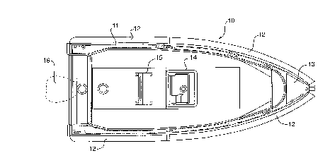
elements throughout several views, Figure 1 shows a boat 10
including a hull 11 and a foam collar 12. The boat shown in Fig.
1 also includes a bow box 13, a console 14, a bolster 15 and an
engine 16.
~ From Figure 1 it can be seen that the preferred embodiment
of the boat of the present invention includes four foam collar
sections 12 which together form the foam collar of the present
invention. The foam collar sections 12 extend around the
periphery of the hull 11.
Referring to Fig. 2, there is shown a side view of the boat
10 of the present invention. From Fig. 2 it can be seen that the
foam collar sections 12 are located on the hull 11 of the boat
10 at a point where the foam collar sections 12 are above the
static waterline of the boat. Preferably, the bottom of the foam
collar section 12 is 5-50 centimeters above the static waterline
so that during normal operation of the boat, the foam collar
remains above the surface of the water. Also shown in Fig. 2 is
the sur~ace coating 20 of the foam collar sections 12 upon which
may be printed, for example, stripes 21, a logo 22 and/or any
other design which may be desirable.
Referring now to Fig. 3, there is shown a cross-sectional
view of the foam collar section 12 along the line III-III of Fig.
CA 02247~43 1998-09-14
2. In the preferred embodiment, the foam collar section 12 is
made up of a laminate 24 of first, second and third layers 31,
32, 33, respectively, of foam material. The laminate 24 of foam
material layers 31-33 is molded preferably to the shape shown in
Fig. 3.
On the outer surface of the laminate 24 is a layer of a
surface coating 20 and a reinforcement coating 23 which, together
are adhered to the laminate 24 by an adhesive layer 25. Laminate
24 is molded so as to have mating surfaces 35, 36 which mate with
portions of the hull 11 of boat 10. However, the entire inner
surface of the molded laminate 24 need not mate with the hull ll
in the preferred embodiment and thus a gap 34 is formed between
the foam collar section 12 and the hull ll as shown in Fig. 3.
The foam collar sections 12 are attached to the hull of the
boat by one or more attachment means 30, one of which is shown
in the detail of Fig. 4. More specifically, the preferred
attachment means 30 includes an attachment,flange 40 which is
formed integrally with and extends from the foam collar section
12. Attachment flange 40 includes a lip 42 at the distal end
thereof. A flat bar, 41, preferably made from aluminum, is used
to attach attachment flange 40 to hull 11 by virtue of a first
fastening means such as a pin 44. The fastening means may be any
other suitable conventional fastener such as a screw 45, bolt,
nail or bracket. Nylon scrim 43 can be used to reinforce
attachment flange 40 to thereby provide additional strength to
bear the load of foam collar sections 12.
The molded laminate 24 of the foam collar section 12 of the
present invention is preferably made from a copolymer closed cell
CA 02247~43 1998-09-14
foam. In particular, three sheets of copolymer are heat fused
together to form the foam laminate 24 and the formed foam
laminate 24 is molded under heating pressure in a mold to produce
the desired shape. A preferred material for the copolymer foam
is cross-linked polyethylene-ethylene vinyl acetate copolymer.
However, other conventional closed cell polymeric foams can be
employed to fabricate the foam collar sections 12 of the present
invention.
The closed-cell polymer foams useful for for making foam
collar sections 12 are chosen based on their density, water
absorption characteristics and compressive strength. Preferred
foams have a density of from about 1.5 lb/ft3 to about 5 lb/ft3
and, more preferably, from about 2 lb/ft3 to about 5 lb/ft3.
Water absorption of the foam is preferably less than 0.1 lb/ft2
using ASTM-D3575-84L. Preferred foams have a compressive
strength from about 5-9 psi at 25% (ASTM-D3575-9lD).
The reinforcement coating 23 of the present invention has
for its purpose to impart strength to the foam lamir.ate 24 and
the attachment flanges 40. Accordingly, the materials used for
the reinforcement coating 23 may be conventional materials known
to provide strength. One preferred material for use as the
reinforcement coating is polyurethane. The reinforcement coating
is applied to a thickness of from about 40 to about 70 mils of
dry film thickness. More preferably, the reinforcement coating
is 50-60 mils thick in dry film thickness. Nylon scrim 43 may be
placed along the attachment flanges 40 and sprayed over with the
reinforcement coating 23 as shown in Figs. 3-4 in order to
provide additional strength to attachment flanges 40.
CA 02247~43 1998-09-14
The reinforcement coating 23 is made from materials having
good abrasive resistance and elongation. Preferred materials
have an abrasive resistance of less than about 1 mg. lost (ASTM
(501) and an elongation of at least about 200~ (ASTM D412). A
preferred material for the reinforcement coating is an abrasive
resistant urethane elastomer.
The surface coating 20 is used primarily to provide a
pleasing aesthetic feel and appearance for the foam collar
sections 12. A preferred material for the surface coating is a
two-component polyurethane system which is pigmented to the
desired color of the foam collar sections 12. The surface
coating 20 is preferably sufficiently thick to cover the entire
outer surface of foam collar sections 12 to thereby provide a
pleasing aesthetic effect for the foam collar sections 12 when
viewed from outside of the boat 10. The surface coating 20,
coating thickness and foam density may also be chosen to be
smooth and soft to the touch. This is useful,for persons getting
into and out of the boat ~ho will touch the foam collar sections
12. In addition, the surface coating 20 may be chosen to impart
abrasion resistance to the outer surface of the foam collar
sections 12 such that when boarding other craft or when docked
at a waterfront the foam collar will not be damaged by abrasion.
- Optionally, detailing can be provided on the outer surface
of the surface coating 20 of the foam collar sections 12. An
example of such detailing is shown in Fig. 2 where stripes 21 and
a logo 22 are included on the outer surface 20 of the foam collar
sections 12. This option provides an additional means of
rendering the foam collar sections 12 aesthetically pleasing and
CA 02247~43 1998-09-14
can be used to strongly influence the overall aesthetic impact
of the boat 10.
Another aspect of the present invention is a method for
making the foam collar. In the first step of the method, a
polymeric foam material is molded using a mold by application of
heat and pressure using conventional molding techniques in order
to provide a polymeric foam of a predetermined shape such as the
shape shown in Fig. 3 which includes a convex outer surface. The
polymeric foam is then removed from the mold and trimmed to
remove flash and any other defects and provide a polymeric foam
material of the desired shape.
The next step in the process is to provide the surface
coating onto the interior of a mold. The surface coating may be
sprayed or brushed onto the interior surface of the mold. Once
the surface coating is applied to the interior surface of the
mold, it is cured to a dry film thickness of from about 3 mils
to about 20 mils thick. The thickness of the surface coating 20
is primarily a function of the desired color and/or surface
characteristics for the foam collar sections 12.
After curing the surface coating, a reinforcement coating
23 is applied to the mold atop the surface coating 20. The
reinforcement coating 23 may also be sprayed, brushed or applied
by any conventional means onto the interior surface of the mold
atop the surface coating 20. The reinforcement coating 23 is
then cured to a dry film thickness of from about 20 to about 70
mils to form a cured reinforcement coating 23. Optionally,
reinforcement mesh, which may be nylon scrim 43, is placed along
the areas where the attachment flanges 40 will fit in the mold
CA 02247~43 1998-09-14
and the strength reinforcement coating 23 is sprayed over the
reinforcement mesh 43 so as to include the reinforcement mesh 43
inside of the reinforcement coating 23 and thereby provide
additional strength to attachment flange 40.
Once the reinforcement coating 23 has been fully cured to
a dry film, an adhesive layer 25 is placed on the cured surface
of the reinforcement coating 23 and on the molded surface of the
copolymer foam laminate 24. The copolymer foam laminate 24 is
then placed in the mold against the adhesion layer 25 and a
vacuum is applied over the entire surface of the mold until the
adhesive layer 25 cures thereby securing the reinforcement
coating 23 directly to the surface of the molded foam laminate
24. Optionally, a flexible polyurethane foam can be applied to
fill voids at the mold ends. The application of the flexible
polyurethane foam can be by spraying, brushing or any other
suitable conventional means. Finally, the completed foam collar
section 12 is removed from the mold and trimmed to remove flash
or any other defects.
The foam collar sections 12 are preferably designed to key
into the molded glass reinforced plastic surface of the hull 11
as shown in Fig. 3. In other words, the mating surfaces 35, 36
are molded to fit closely with the outer surface of the hull 11
as shown in Fig. 3. The foam collar sections could also fit onto
an aluminum hull with a similar shape as the glass reinforced
plastic hull. The foam collar sections 12 are mechanically
attached to the hull 11 by any suitable attachment means. An
example of the attachment means are aluminum flat bars 41 which
key into a molded lip 42 around the perimeter of the molded
CA 02247~43 1998-09-14
surface on the attachment flanges 40. The foam collar sections
12 may then be glued together and the seams between the foam
collar sections 12 can be reinforced using a polyvinyl chloride
seam tape which is glued into place. In this manner, water can
be prevented from entering between the foam collar sections 12.
The mating surfaces 35, 36 which key into the hull 11 also help
prevent water from coming between foam collar sections 12 and
hull 11.
The foam collar of the present invention provides several
advantages over prior art constructions which may be used for the
same purpose. First, the foam collar of the present invention
allows an increase in the inside space of the boat due to the
placement of the foam collar on the outside of the hull 11 and
above the static waterline of the boat 10. Further, the foam
collar of the present invention provides a soft fendering effect
which is useful when boarding other boats or mooring the boat
since it will prevent damage to the hull of the boat when it
comes into contact with other boats or docks.
The foam collar of the present invention may be fabricated
to be aesthetically pleasing since it includes a surface coating
20 which can be of a selected color and because the surface
coating 20 can be chosen to allow the application of designs
and/or logos on the surface coating 20. Further, designs can be
molded into the foam collar sections 12 of the present invention
in order to provide a three-dimensional textured effect on the
outer surface of the foam collar sections 12.
Finally, the foam collar sections 12 of the present
invention can be made smooth and soft to the touch, are abrasion
... _ . ...
CA 02247543 1998-09-14
resistant and require little or no maintenance since they are not
inflatable. Finally, the foam collar of the present invention
can be fabricated by the relatively inexpensive molding process
described above.
The foregoing description of the invention has been provided
for the purposes of illustration and description only. The scope
of the invention is to be determined from the claims appended
hereto.
13