Note : Les descriptions sont présentées dans la langue officielle dans laquelle elles ont été soumises.
CA 02247866 1998-08-28
-1/1-
CARBURETOR WITH FUEL NOZZLE
FIELD OF THE INVENTION
The present invention generally relates to the field
of carburetors that mix air and fuel for internal
combustion engines and, more particularly, to the field
of fuel nozzles that provide fuel to the throat of such
carburetors.
BACKGROUND OF THE INVENTION
Background art includes French reference FR-E-
26,901, which discloses a fuel nozzle (1) having a pair
of upstream orifices (2) and which is interconnected to
a fuel conduit (5). French reference FR-A-555,986
- 15 discloses a fuel nozzle (1) disposed in a carburetor and
in fluid communication with a fuel line (6). Another
background art reference is British reference GB-A-
649,920, which discloses a fuel nozzle (13) having an
upstream orifice (24) and a downstream orifice (23)
disposed within a carburetor. The fuel nozzle is angled
with respect to the flow of air through the carburetor,
and fuel within the fuel nozzle blocks the upstream
orifice (24) during high suction and low engine speeds.
Another background art reference is British reference GB-
A-148,507, which discloses a fuel nozzle or choke tube
(g) having an air inlet orifice (k) and a orifice for the
outflow of fuel (kl). Fuel is drawn through the choke
tube (g) from a chamber (d) containing a constant level
(indicated by line 1-1) of fuel.
In conventional carburetors, air enters through an
intake of a carburetor throat and travels through a
venturi where the air is mixed with fuel and subsequently
provided to a combustion chamber of the engine. Fuel is
typically provided to the air by a fuel nozzle that is
operatively interconnected with a fuel supply (e.g., a
fuel bowl). The fuel nozzle extends transversely into
the carburetor throat, and includes an outlet port in a
tip thereof. The outlet port commonly faces transverse
CA 02247866 1998-08-28
r
-1/2-
to the air flow such that air passing over the port will
create a negative pressure, thereby resulting in fuel
being drawn from fuel nozzle.
In some engines, air can also flow in the reverse
direction (i.e., from the combustion chamber toward the
carburetor intake), sometimes called "reverse flow."
Reverse f low is typically caused by intake valve leakage,
which can result from valve lash, inconsistent cam
profiles or poor valve seals. Due to the presence of an
air velocity, reverse flow creates a negative pressure at
the outlet port, resulting in fuel being drawn from the
fuel nozzle. When forward flow resumes, fuel is again
drawn from the fuel nozzle, resulting in a "double
charge" of fuel. This double charge creates an air/fuel
ratio that is richer than the optimum air/fuel ratio of
the carburetor, resulting in excess emissions and lower
fuel economy.
CA 02247866 2004-05-27
o~3s3-11.1s
-2 -
SUMMARY OF THE INVEN'fzON
The p~teeexit invention provides a carburetor with a
fuel nozz~.e that alleviates the problem of double Charging _
by positioning orifices in the fuel nozzle such that more
fuel is dispensed during downstream gas flow than during
upstream gas flow. In one aspect, the present invention
provides a carburetor comprising: a carburetor body having "
a throat extending from an intake to a discharge, wherein a '
downstream direction is defined as extending from said
intake toward said discharge, and wherein an upstream
direction is defined as extending from said discharge toward
said intake; and a fuel nozzle having body, said body having
a longitudinal axis positioned within sand throat such that _.
said longitudinal axis ie substantially normal to said
upstream and downstream direct~.vna, said nozzle including at
least one upstream orifice facing substantially upstream and
at least one downstream orifice facing substantially
downstream, wherein a surface area of said at least one w
upstream orifice is lees than about 5o percent of a surface ,
2o area of said at least one downstream orifice, wherein said
upstream orifice is sized and positioned to allow air to
enter maid fuel rxozxle at a right angle to a flow of fuel in
said nuzzle during downstream flow of air in said carburetor
threat to cause improved fuel atomization in said fuel
nozzle before said fuel and air exit said downstream orifice
during normal operation of the engine.
zn one embodiment, the sux'face ax~2a of the
upstream orifice can be less than about 50 percent,
preferably less than about 25 percent, and more preferably
between about S percent and about 20 percent of the surface
area of the downstream orifice. Tn another embodiment, the
fuel nozzle supplies fuel through a carburetor wall, and the
CA 02247866 2004-05-27
~7363~2118
i.:E
-2a-
upstream orifice is positioned closer to the carburetor wall
than any of the downstream orifices. Fvr example, the
upstream orifice can be positioned adjacent the carburetor
body that fvrtns the throat. I~et yet another embodiment, the r~;
downstream orifice includes a plurality of downstream
orifice . Preferably, the plurality of downstream orifices
have an average po~sitiori that ie centered ~,rith respect to
the throat. For. example, the downstream orifice cart include
three
~:3,
t~ .
F .~y
CA 02247866 1998-08-28
WO 97/37180 PCT/US97/00684
-3-
downstream orifices, wherein one of the three downstream
orifices is centered with respect to the throat, and
wherein the other two downstream orifices are evenly
' spaced on opposing sides of the centered downstream
orif ice .
' In another aspect, the invention is embodied in a
carburetor comprising a carburetor body having a throat
extending from an intake to a discharge, and a fuel
nozzle positioned within the throat and supplying fuel
through a carburetor wall. The fuel nozzle includes at
least one upstream orifice facing substantially upstream
and at least one downstream orifice facing substantially
downstream, and at least one of the upstream orifices is
positioned closer to the carburetor wall than all of the
downstream orifices. Preferably, the upstream orifice
includes only one upstream orifice, and the downstream
orifice includes a plurality of downstream orifices that
have an average position that is centered with respect to
the throat.
In yet another aspect, the present, invention
includes a carburetor including a carburetor body having
a throat extending from an intake to a discharge, and a
fuel nozzle positioned within the throat and including at
least one upstream orifice facing substantially upstream
and at least one downstream orifice facing substantially
downstream, wherein a combined surface area of all
upstream orifices is less than a combined surface area of
all downstream orifices. In one embodiment, the surface
area of the upstream orifice can be less than about 50
percent, preferably less than about 25 percent, and more
preferably between about 5 percent and about 20 percent
of the surface area of the downstream orifice.
BRIEF DESCRIPTION OF THE DF~~1~WINGS
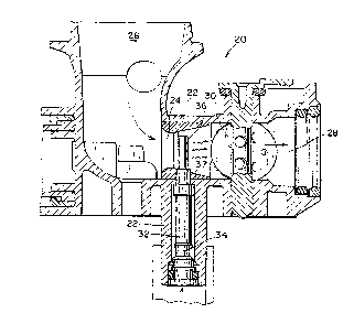
Fig. 1 is a side section view of a carburetor
embodying the present invention and including a fuel
nozzle.
CA 02247866 1998-08-28
WO 97/37120 PCT/LTS97/00684
-4-
Fig. 2 is a longitudinal section view of the fuel
nozzle illustrated in Fig. 1.
Fig. 3 is a section view of the fuel nozzle taken
along line 3-3 in Fig. 2. ~
Fig. 4 is an end view of the fuel nozzle taken along
line 4-4 in Fig. 2. '
Fig. 5 is a side section view of a different
carburetor embodying the present invention and including
a fuel nozzle.
Fig. 6 is a longitudinal section view of the fuel
nozzle illustrated in Fig. 5.
Fig. 7 is an end view of the fuel nozzle taken along
line 7-7 in Fig. 6.
Figs. 8-12 illustrate various fuel nozzles embodying
the present invention.
ETAILED DESCRIPTION
Fig. I illustrates a carburetor 20 having a
carburetor body 22 with a carburetor throat 24 extending
therethrough from an intake region 26 to a discharge
region 28. The carburetor 20 further includes a throttle
that regulates the amount of air and fuel passing
through the throat 24. A fuel nozzle 32 is positioned to
provide fuel to the throat 24. The fuel nozzle 32
25 generally includes a base 34 mounted to the carburetor
body 2 2 , and a tip 3 6 extending f rom the base 3 4 , through
a carburetor wall 37, and at least partially positioned
within the carburetor throat.
In accordance with the present invention, the tip 36
30 is provided with an upstream orifice and at least one
downstream orifice having a surface area 3arger than a
surface area of the upstream orifice. As used herein,
the term "surface area" is used to describe the orifice's
propensity to discharge fuel. That is, the larger the '
surface area of the orifice, the more fuel it is likely
to discharge given a particular pressure. The surface
area values used herein refer to the area of the orifice
at the outer surface of the fuel nozzle. It should be
CA 02247866 1998-08-28
WO 97/37120 PCT/ITS97/00684
-5-
appreciated, of course, that other techniques could be
used to achieve the present invention. For example, by
using narrow slot-shaped or pinhole openings, surface
' tension could also play a role in an orifice's propensity
to dispense fuel. Further, orifices that change in area
' from the surface inward could also affect the orifice's
performance .
In the embodiment illustrated in Figs. 1 and 2, the
tip includes one upstream orifice 38 that is circular and
IO has a diameter of about .021 inches, corresponding with
a cross-sectional surface area of about .00035 square
inches. The illustrated embodiment includes three
downstream orifices 40,42,44 that are each circular and
have a diameter of about .037 inches, corresponding with
a total cross-sectional surface area of about .00323
square inches. It should be appreciated that the
orifices do not need to be round in cross-section, and
could instead be configured in other appropriate shapes.
As best shown in Fig. 2, the middle downstream
orifice 42 is approximately centered with respect to the
throat 24, and the other two downstream orifices 40,44
are equally spaced on either side of the middle
downstream orifice 42. Accordingly, the downstream
orifices 40,42,44 are positioned in a pattern that is
evenly distributed across the throat 24. In contrast,
the upstream orifice 38 is positioned off-center with
respect to the throat 24. More specifically, the
upstream orifice 38 is positioned closer to the
carburetor wall 37 than any of the downstream orifices
40,42,44, as shown in Figs. I and 2.
By virtue of the positioning of the downstream side
of the nozzle tip, double charging is significantly
reduced. More specifically, forward flow will create a
low pressure at the downstream orifices, resulting in
fuel being dispensed through the downstream orifices.
During reverse flow, a high pressure is formed at the
downstream orifices, resulting in little or no fuel being
CA 02247866 1998-08-28
WO 97/3'7120 PCT/US97/00684
-6-
dispenses through the downstream orifices. Accordingly,
double charging is significantly reduced.
The positioning of the upstream orifice allows air
to enter the fuel nozzle at a right angle to the flow of
fuel in the nozzle during forward flow. The right angle
motion of the air relative to the fuel causes shearing of
the fuel in the fuel nozzle, resulting in better fuel
atomization as the fuel arid air exit the downstream
orifices. Because of the small surface area of the
1.0 upstream orifice relative to the downstream orifices,
reverse flow will not result in significant dispersal of
fuel through the upstream orifice.
As noted above, the fuel nozzle 32 includes a tip 36
and a base 34. The tip 36 and the base 34 can be made
from a wide variety of materials, including metals and
plastics. In the embodiment illustrated in Figs. 1-4,
the tip 36 and the base 34 are machined from metallic
material, such as SAE CA 332 Brass, and the base 34 is
press fit into the tip 36. The utilization of a two-
piece fuel nozzle facilitates production of a fuel nozzle
32 having a tip 36 with a thinner wall than the base 34.
The thinner wall allows the tip to occupy less space
within the throat, thereby improving engine performance.
To insure proper alignment of the base 34 with the tip
36, the base 34 includes a flat surface 46 that
corresponds with a flat segment 48 on the tip 36, as
shown in Fig. 3. Further, to insure that the assembled
fuel nuzzle 32 is properly inserted into the carburetor
body 22, the base 34 includes a flat portion 50 that
matches the shape of the carburetor body 22, as shown in
Fig. 4.
The carburetor 60 illustrated in Fig. 5 includes an '
integral fuel bowl 62 and associated float 64 for
providing fuel to the carburetor throat 66 via a metering '
orifice 68 and a fuel nozzle 70. Referring to Fig. 6,
the fuel nozzle 70 is a one-piece design made from
plastic, such as acetal resin. The lower portion of the
fuel nozzle includes a D-shaped base portion 72, as shown
CA 02247866 1998-08-28
WO 97/37I2~ PCT/LT897/00684
in Fig. 7, to insure proper alignment of the fuel nozzle
70 with the carburetor body 74.
Fig. 8 illustrates another fuel nozzle 80 embodying
' the present invention. The fuel nozzle 80 is a two-piece
design, including a tip 82 and a base 84. The tip 82 and
' the base 84 are both made of plastic material, such as
Delrin, a trademark of E.I. Du Pont De Nemours Of
Wilmington, Delaware. The tip 82 and the base 84 are
interconnected by a snap fit, wherein a ridge 86 on the
t3_p 82 fits into a groove 88 on the base 84. In the
i7.lustrated embodiment, the tip 82 has a wall thickness
that is about the same as the wall thickness of the base
8 9: .
Fig. 9 illustrates another fuel nozzle 90 embodying
the present invention. The illustrated fuel nozzle 90 is
a one-piece design that is machined from a metallic
material, such as brass. A tip portion 92 of the fuel
nozzle 90 is blocked by a ball plug 94.
Fig. 10 illustrates a fuel nozzle 100 embodying the
present invention. Similar to the fuel nozzle
illustrated in Fig. 8, the fuel nozzle 100 of Fig. IO is
a two-piece Delrin design wherein a tip 102 is snap fit
with a base 104. The end of the tip 102 includes a ball
plug I06 integrally formed therewith via a flexible
interconnecting member 108. The open end of the tip 102
can be selectively closed by inserting the ball plug 106
into the open end.
Fig. 11 illustrates another fuel nozzle 110
embodying the present invention. The fuel nozzle 110 is
identical. to that illustrated in Fig. 8, except the tip
112 has a wall thickness that is significantly thinner
than the wall thickness of the base 114.
Fig. 12 illustrates a two-piece brass fuel nozzle
. 120 having a tip 122 and a base 124 press fit into the
tip 122. In contrast to the previously-described fuel
nozzles, the tip 122 illustrated in Fig. 12 extends only
partially (e. g., less than halfway) into the carburetor
throat 126. Further, the tip 122 illustrated in Fig. 12
CA 02247866 1998-08-28
WO 97/37120 PCT/US97/00684
_g_
includes only one downstream orifice 128, rather than the
three downstream orifices illustrated in the other fuel
nozzles. As shown, the downstream orifice 128 has a
cross-sectional surface area that is significantly larger
S than the surface area of the upstream orifice 130.
The foregoing description of the present invention
has been presented for purposes of illustration and
description. Furthermore, the description is not
intended to limit the invention to the form disclosed
herein. Consequently, variations and modifications
commensurate with the above teachings, and the skill or
knowledge of the relevant art, are within the scope of
the present invention. The embodiments described herein
are further intended to explain best modes known for
practicing the invention and to enable others skilled in
the art to utilize the invention in such, or other,
embodiments and with various modifications required by
the particular applications or uses of the present
invention. It is intended that the appended claims be
construed to include alternative embodiments to the
extent permitted by the prior art.