Sélection de la langue

Search

Sommaire du brevet 2248423 

Énoncé de désistement de responsabilité concernant l'information provenant de tiers

Une partie des informations de ce site Web a été fournie par des sources externes. Le gouvernement du Canada n'assume aucune responsabilité concernant la précision, l'actualité ou la fiabilité des informations fournies par les sources externes. Les utilisateurs qui désirent employer cette information devraient consulter directement la source des informations. Le contenu fourni par les sources externes n'est pas assujetti aux exigences sur les langues officielles, la protection des renseignements personnels et l'accessibilité.

Disponibilité de l'Abrégé et des Revendications

L'apparition de différences dans le texte et l'image des Revendications et de l'Abrégé dépend du moment auquel le document est publié. Les textes des Revendications et de l'Abrégé sont affichés :

  • lorsque la demande peut être examinée par le public;
  • lorsque le brevet est émis (délivrance).
(12) Brevet: (11) CA 2248423
(54) Titre français: ELEMENT DE FIXATION RIGIDE D'APPAREIL D'ECLAIRAGE
(54) Titre anglais: RIGID LIGHT FIXTURE MOUNTING BRACKET
Statut: Périmé et au-delà du délai pour l’annulation
Données bibliographiques
(51) Classification internationale des brevets (CIB):
  • F21V 23/02 (2006.01)
  • F21V 15/00 (2015.01)
  • F21V 17/00 (2006.01)
(72) Inventeurs :
  • SPITLER, BRIAN L. (Etats-Unis d'Amérique)
(73) Titulaires :
  • REGENT LIGHTING CORPORATION
  • REGENT LIGHTING CORPORATION
(71) Demandeurs :
  • REGENT LIGHTING CORPORATION (Etats-Unis d'Amérique)
  • REGENT LIGHTING CORPORATION (Etats-Unis d'Amérique)
(74) Agent: FINLAYSON & SINGLEHURST
(74) Co-agent:
(45) Délivré: 2002-05-28
(22) Date de dépôt: 1998-09-25
(41) Mise à la disponibilité du public: 1999-04-23
Requête d'examen: 1998-11-19
Licence disponible: S.O.
Cédé au domaine public: S.O.
(25) Langue des documents déposés: Anglais

Traité de coopération en matière de brevets (PCT): Non

(30) Données de priorité de la demande:
Numéro de la demande Pays / territoire Date
08/956,978 (Etats-Unis d'Amérique) 1997-10-23

Abrégés

Abrégé français

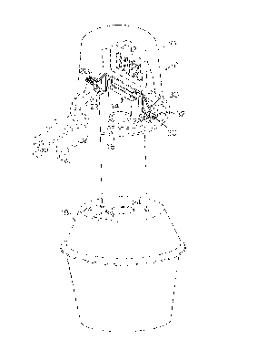
Élément de fixation rigide servant à fixer un transformateur à un appareil d'éclairage électrique. Le dispositif de fixation présente deux extrémités conçues pour recevoir des attaches servant à monter l'élément de fixation sur l'appareil d'éclairage. L'élément de fixation rigide résiste au déplacement et à la flexion, avant et pendant l'installation du transformateur, ce qui permet de fixer ce dernier facilement et rapidement à l'appareil d'éclairage.


Abrégé anglais


A rigid support bracket mounts a transformer to an electrical light fixture. The bracket
is formed with end portions adapted to receive fasteners therethrough for mounting the bracket
to the electrical fixture. The rigid support bracket resists undesired shifting or bending of the
bracket before and during transformer installation, thus providing easy and quick installation of
a transformer to a light fixture.

Revendications

Note : Les revendications sont présentées dans la langue officielle dans laquelle elles ont été soumises.


THE CLAIMS
What Is Claimed Is:
1. A rigid light fixture mounting bracket for mounting an electrical light fixture assembly
having as components thereof a transformer, an upper light fixture housing, a lower lamp
housing, and a lamp bulb socket, comprising:
(a) a first brace member formed of a single flat, metallic strip bounded by top and
bottom surfaces having:
i) horizontally oriented co-planar and longitudinally spaced first and second
end portions; and
ii) a horizontally oriented first middle platform portion located between said
end portions, offset from and residing in a plane parallel to and above the
plane of said first and second end portions and joined thereto;
(b) a second brace member bounded by top and bottom surfaces and formed of a
single flat, metallic strip having:
i) horizontally oriented, coplanar, longitudinally third and fourth and portions
the top surfaces of said third and fourth end portions being located
immediately adjacent and permanently joined to respective bottom surfaces
of said fist and second end portions;
ii) a pair of longitudinally spaced, coplanar, horizontal upper platform
portions offset from and residing in a plane parallel to and above the plane
of said third and fourth end portions, the top surfaces of said upper

platform portions being located immediately adjacent to and permanently
joined to the bottom surface of said first brace member middle portion;
iii) a horizontally oriented second middle platform portion located between
said upper platform portions, offset from and residing in a plane parallel
to and below the plane of said upper platform portions and joined thereto;
and
iv) a pair of horizontally oriented, coplanar longitudinally spaced, lower
platform portions offset from and residing in a plane parallel to and below
the plane of said upper platform portions and connected thereto;
(c) means effecting said joins wherein said first and second brace members provide
an initial rigid brace structure suitable for said mounting;
(d) the top surface of said first brace member first middle platform portion being
adapted for being attached to said transformer;
(e) the respective top surfaces of said first and second end portions being adapted for
mounting said upper light fixture housing;
(f) the lower platform portions being adapted for mounting said lower lamp housing;
and
(g) the bottom surface of said second middle platform portion being adapted for
mounting said lamp bulb socket.
2. A rigid light fixture mounting bracket as claimed in claim 1 wherein said means for
effecting said joins comprises spot welds at the respective locations of said joins.

11
3. A rigid light fixture mounting bracket as claimed in claim 1 including means for
attaching:
(i) said transformer to the top surface of said first brace member first middle platform
portion;
(ii) said upper light fixture housing to the respective top surfaces of said first and
second end portions;
(iii) said lower lamp housing to the said lower platform portions; and
(iv) said lamp bulb socket to the bottom surface of said second middle platform
portion.
4. A rigid light fixture mounting bracket as claimed in claim 1 including fastener receiving
apertures formed:
(i) through said first and third end portions where joined;
(ii) through said second and fourth end portions where joined;
(iii) through said second middle platform; and
(iv) through each of said lower platform portions.

Description

Note : Les descriptions sont présentées dans la langue officielle dans laquelle elles ont été soumises.


CA 02248423 1998-09-25
RIGID LIGHT FIXTURE MOUNTING BRACKET
BACKGROUND OF THE INVENIION
Field of Invention
This invention relates generally to a support device for supporting a transformer within
a light fixture and more specifically to a rigid light fixture mounting bracket that fits within a
light fixture.
Description of the Related Art
Transforrners are used to magnetically couple ~lt~rn~ting current voltages from one point
in a circuit to another, or to increase or decrease the alternating current voltage. Transformers
are generally mounted within fixtures so that they will not shift during operation and touch other
conducting or grounded devices which could damage the transforrners and fixtures.
Traditionally, in order to prevent shifting of a fixture enclosed ~lan~Çolll.er, the
transforrner has been affixed to a mounting bracket or the like which mounts the transformer to
the fixture and prevents the tran~Çollller from shifting during operation. More recently,
transformers have been mounted inside small fLlctures. Therefore, the mounting bracket must also
be adapted to fit inside any of various types of small fixture, each of which typically requires a
mounting bracket having a shape that conforms to the particular structural configuration of a
particular fixture. For example, Figure 1 shows a prior art light fLxture P comprising a upper
light fLlcture housing 10, transformer 12, tr~ncfnrrnçr mounting bracket 14, light bulb socket 16,
and a lower lamp housing 18. Transformer mounting bracket 14 is typically forrned of a material
such as a steel strip which is capable of being bent into the particular shape that will fit within

CA 02248423 1998-09-2S
the particular relatively small upper light fixture housing 10 in which the bracket is installed.
As shown in Figure 2, the bottom surface of the transformer 12 is attached to the top surface of
transformer mounting bracket 14. Additionally, Figure 2 shows in further detail a typical shape
of a prior art transformer mounting bracket 14 designed to fit the type of light fixture seen in
Figure 1.
Referring further to Figure 1, transformer mounting bracket 14 is attached to fixture
housing 10 by aligning transformer mounting bracket apertures 20 with mating apertures (not
shown) of fixture housing 10 and attaching them together with fasteners, such as screws.
Additionally, the lower lamp housing 18 is attached to the transforrner mounting bracket 14 by
aligning lens first bracket member apertures 22 with lower lamp housing apertures 24 and
attaching them together with screws.
It is critical that the transformer mounting bracket screw receiving apertures 20 correctly
align with the corresponding apertures of the fixture housing. A major problem with the prior
art transformer mounting device is that the traditional transformer mounting bracket is formed
of a material that can bend and otherwise contort before, during, or after installation. Relatively
heavy transformers increase stress on their corresponding mounting brackets and, thus, typically
bend the mounting bracket from its initial preferred shape. If the mounting bracket is bent from
its original positioning alignment, its apertures will not align with the screw receiving apertures
of the f~ture housing. Furthermore, the lens mounting bracket apertures may not properly align
with the apertures of the lower larnp housing, making it difficult to attach the lower lamp housing
to the fixture housing. Bending of the transforrner mounting bracket from its original preferred
shape, causes an installer of such a fixture much aggravation as he or she tries to bend the

CA 02248423 1998 - 09- 25
bracket to its preferred shape, thereby possibly causing damage to the fixture, transformer, and
the lower lamp housing.
It is therefore an object of this invention to provide a support brace for a transformer
mounting bracket, which, when permanently attached thereto, prevents the resulting rigid light
fixture mounting bracket of the invention from bending from its desired form.
It is another object of this invention to provide a rigid light fixture mounting bracket to
make installation of transformers into light fixtures quick and easy.
It is a further object of this invention to provide a rigid light fixture mounting bracket
which is inexpensive and durable.
Other objects will become apparent as the description proceeds.
SUMMARY OF THE INVENTION
In the preferred embodirnent, the traditional transforrner bracket is reinforced by the
support brace of the invention which comprises a rectangular strip of metal shaped near each end
portion so as to form a bridge-like structure. The support brace has a top and bottom surface and
a screw receiving aperture at each end. The support brace of the invention spans the traditional
transformer mounting bracket and is perm~nently affixed thereto. A transformer is permanently
mounted to the top surface of the support brace. The support brace of the invention when used
in combination with the traditional transformer mounting bracket forms a highly rigid light fixture
mounting bracket that will not bend prior to or during normal installation, and further prevents
the attached transformer from shifting during operation. The rigid light fixture mounting bracket
of the invenhon furthermore provides for quick and easy fLxnlre assembly.

CA 02248423 1998 - 09- 25
BRIEF DESCRIPllON OF THE DRAWlNGS
Figure 1 is a perspective view of a prior art light fixture showing a prior art transformer
mounting bracket and transformer mounted thereto, the light fixture and transformer are shown
in dotted lines;
Figure 2 is a side view of the transformer and prior art transformer mounting bracket
shown in Figure 1, the transformer is shown in dotted lines;
Figure 3 is a perspective view of the light fixture of Figure 1 equipped with the rigid
support brace of the invention, the light fixture and transforrner are shown in dotted lines;
Figure 4 is a side view of the rigid light fixture mounting bracket of the invention, the
transformer is shown in dotted lines;
Figure 5 is a bottom perspective view of the rigid light fixture mounting bracket of the
invention;
Figure 6 is an end view of the rigid light fxture mounting bracket of the invention shown
in Figure S;
Figure 7 is a top view of the rigid light fixture mounting bracket of the invention showing
in particular a top view of the support brace shown in Figure S; and
Figure 8 is a bottom view of the rigid light fixture mounting bracket of the invention
shown in Figure 5.

CA 02248423 1998-09-2~
DETAILED DESCRIErrION OF THE INVENTION AND
PREFERRED EMBODIMENT THEREOF
Figure 3 shows a perspective view of a light fL~cture in combination with the support brace
(hereinafter referred to as the "first brace member 30") and a traditional transformer mounting
bracket (hereinafter referred to as the "second brace member 14"). The first and second brace
members 30, 14, respectively, are permanently joined as described below and are hereinafter
collectively referred to as the rigid light fixture mounting bracket 32 of the invention.
More par~icularly, Figure 4 illustrates first brace member 30 fLxedly attached to and spanning
second brace member 14. First brace member 30 is a rectangular strip of metal having
horizontally oriented co-planar lon~i~uclin~lly spaced first and second end portions 34, 36 with
top surface 38 and bottom surface 40. A horizontally oriented first middle portion 46 is offset
from and the above plane of first and second end portions 34, 36. Between first middle portion
46 and first and second end portions 34, 36, first brace member 30 is bent downwardly from the
horizontal plane approximately 45 degrees (angles 42) to cause first brace member 34, 36 to
assume a 450 slope and is then bent (angles 44) back to the horizontal plane such that first and
second ends 34, 36 are oriented horizontal and parallel to the first middle portion 46 of first brace
member 30 to form a bridge-like structure. Figures 4 and 5 illustrates second brace member 14
formed of a flat, metallic strip m~teri~l having a horizontally oriented co-planar longitudinally
spaced third and fourth end portions 48, 50. The top surface of third and fourth end portions 48,
50 are irnmediately adjacent to first and second end portions 34, 36 and are secured by welding
or the like to first brace member 30 first and second ends 34, 36 respectively. Between opposed
ends 48, 50 of second brace member 14, is a raised pair of horizontally oriented subplatforms

CA 02248423 1998 - 09- 2~
52, 54 offset from and above the plane of said third and fourth end portions 48, 50 and a lowered
horizontally oriented second ~uddle platform 56. The top surfaces of subplafforms 52, 54 and
of third and fourth end porhons 48, 50 are permanently fixed by welding or the like to the
bottom surface of the first middle porhon 46 of first brace member 30 and first and second end
portions 34, 36 respectively to form one rigid light fixture mounhng bracket 32 of the invention.
Second brace member 14 has recessed ends 20 which align with apertures 60 (shown in Figure
7) of first brace member 30. Addihonally, second brace member 14 has a pair of fastener
receiving apertures 62 extending through subplatforms 56, 58 for mounhng lower lamp housing
18 to rigid light fixture mounhng bracket 32 of the invenhon. As illushrated in Figures S and 8,
two sets of apertures 64, 66, and 68 extend through the midsechon of subplatform 56, and are
for mounting light bulb socket 16 (Figure 3) to rigid light fixture mounhng bracket 32 of the
mvenhon.
The length of the first brace member 30 is coterminous with the length of the second
brace member 14. The first brace member 30 and second brace member 14 combinahon causes
the resulting rigid light fixture mounting bracket 32 of the invention to be extremely rigid,
preventing undesired bending before, during, or after installation. Figure 6 further illustrates
recessed end 20 of second brace member 14.
The rigid light fixture mounting bracket 32 of the invention is made of a metal material.
However, it can be made of any nonmetallic material that is sturdy enough to prevent bending
from its desired form before, during, or after inst~ hon.
Although the drawings show a conventional transformer mounting bracket with the unique
brace of the invention, different shaped first brace members can be designed to work with other

CA 02248423 1998-09-25
shaped second brace members provided that the first brace member of the present invention be
formed to substantially bridge the particular second brace member.
Wbile the invention has been described with reference to a specific embodiment thereof,
it will be appreciated that numerous variations, modifications, and embo(liment.~ are possible, arld
will become apparent to those skilled in the art. Accordingly, all such variations, modifications,
and embo~liments are to be regarded as being within the spirit and scope of the invention, and
which are intende~l to be incorporated herein.

Dessin représentatif
Une figure unique qui représente un dessin illustrant l'invention.
États administratifs

2024-08-01 : Dans le cadre de la transition vers les Brevets de nouvelle génération (BNG), la base de données sur les brevets canadiens (BDBC) contient désormais un Historique d'événement plus détaillé, qui reproduit le Journal des événements de notre nouvelle solution interne.

Veuillez noter que les événements débutant par « Inactive : » se réfèrent à des événements qui ne sont plus utilisés dans notre nouvelle solution interne.

Pour une meilleure compréhension de l'état de la demande ou brevet qui figure sur cette page, la rubrique Mise en garde , et les descriptions de Brevet , Historique d'événement , Taxes périodiques et Historique des paiements devraient être consultées.

Historique d'événement

Description Date
Inactive : CIB attribuée 2022-11-07
Inactive : CIB expirée 2015-01-01
Inactive : CIB enlevée 2014-12-31
Le délai pour l'annulation est expiré 2006-09-25
Inactive : CIB de MCD 2006-03-12
Lettre envoyée 2005-09-26
Accordé par délivrance 2002-05-28
Inactive : Page couverture publiée 2002-05-27
Préoctroi 2002-03-19
Inactive : Taxe finale reçue 2002-03-19
Un avis d'acceptation est envoyé 2001-09-24
Lettre envoyée 2001-09-24
Un avis d'acceptation est envoyé 2001-09-24
Inactive : Approuvée aux fins d'acceptation (AFA) 2001-08-16
Lettre envoyée 1999-09-27
Inactive : Transfert individuel 1999-09-08
Inactive : Page couverture publiée 1999-05-24
Demande publiée (accessible au public) 1999-04-23
Lettre envoyée 1998-12-21
Inactive : CIB attribuée 1998-12-01
Inactive : CIB en 1re position 1998-12-01
Symbole de classement modifié 1998-12-01
Requête d'examen reçue 1998-11-19
Exigences pour une requête d'examen - jugée conforme 1998-11-19
Toutes les exigences pour l'examen - jugée conforme 1998-11-19
Inactive : Lettre de courtoisie - Preuve 1998-11-10
Inactive : Certificat de dépôt - Sans RE (Anglais) 1998-11-05
Exigences de dépôt - jugé conforme 1998-11-05
Demande reçue - nationale ordinaire 1998-11-04

Historique d'abandonnement

Il n'y a pas d'historique d'abandonnement

Taxes périodiques

Le dernier paiement a été reçu le 2001-06-27

Avis : Si le paiement en totalité n'a pas été reçu au plus tard à la date indiquée, une taxe supplémentaire peut être imposée, soit une des taxes suivantes :

  • taxe de rétablissement ;
  • taxe pour paiement en souffrance ; ou
  • taxe additionnelle pour le renversement d'une péremption réputée.

Veuillez vous référer à la page web des taxes sur les brevets de l'OPIC pour voir tous les montants actuels des taxes.

Historique des taxes

Type de taxes Anniversaire Échéance Date payée
Taxe pour le dépôt - générale 1998-09-25
Requête d'examen - générale 1998-11-19
Enregistrement d'un document 1999-09-08
TM (demande, 2e anniv.) - générale 02 2000-09-25 2000-09-13
TM (demande, 3e anniv.) - générale 03 2001-09-25 2001-06-27
Taxe finale - générale 2002-03-19
TM (brevet, 4e anniv.) - générale 2002-09-25 2002-06-25
TM (brevet, 5e anniv.) - générale 2003-09-25 2003-08-05
TM (brevet, 6e anniv.) - générale 2004-09-27 2004-08-09
Titulaires au dossier

Les titulaires actuels et antérieures au dossier sont affichés en ordre alphabétique.

Titulaires actuels au dossier
REGENT LIGHTING CORPORATION
Titulaires antérieures au dossier
BRIAN L. SPITLER
Les propriétaires antérieurs qui ne figurent pas dans la liste des « Propriétaires au dossier » apparaîtront dans d'autres documents au dossier.
Documents

Pour visionner les fichiers sélectionnés, entrer le code reCAPTCHA :


Pour visualiser une image, cliquer sur un lien dans la colonne description du document. Pour télécharger l'image (les images), cliquer l'une ou plusieurs cases à cocher dans la première colonne et ensuite cliquer sur le bouton "Télécharger sélection en format PDF (archive Zip)" ou le bouton "Télécharger sélection (en un fichier PDF fusionné)".

Liste des documents de brevet publiés et non publiés sur la BDBC .

Si vous avez des difficultés à accéder au contenu, veuillez communiquer avec le Centre de services à la clientèle au 1-866-997-1936, ou envoyer un courriel au Centre de service à la clientèle de l'OPIC.


Description du
Document 
Date
(aaaa-mm-jj) 
Nombre de pages   Taille de l'image (Ko) 
Description 1998-09-25 7 249
Abrégé 1998-09-25 1 12
Dessins 1998-09-25 4 75
Revendications 1998-09-25 3 80
Page couverture 1999-05-19 1 37
Page couverture 2002-04-25 1 31
Dessin représentatif 1999-05-19 1 8
Certificat de dépôt (anglais) 1998-11-05 1 163
Accusé de réception de la requête d'examen 1998-12-21 1 177
Courtoisie - Certificat d'enregistrement (document(s) connexe(s)) 1999-09-27 1 139
Rappel de taxe de maintien due 2000-05-29 1 109
Avis du commissaire - Demande jugée acceptable 2001-09-24 1 166
Avis concernant la taxe de maintien 2005-11-21 1 173
Correspondance 2002-03-19 1 30
Correspondance 1998-11-10 1 31