Note : Les descriptions sont présentées dans la langue officielle dans laquelle elles ont été soumises.
CA 02248719 1998-09-04
W097/33073 PCT/GB97/~621
CONrNUOUSLYROTATNGENG~
The present invention relates to engines, and in particular
to a rotary inertia-recoil free-piston engine.
Engines, in particular of the internal combustion variety,
are well known and generally work to either a two or a four
stroke principle.
In this regard, the term 'stroke' refers to different
operational stages of the engine, namely in a four stroke
engine, an induction stroke, a compression stroke, a power
stroke and an exhaust stroke.
A common principle of such engines is that the reciprocating
action of a piston within a cylinder is converted via a
connecting rod and a crank shaft arrangement into rotational
movement of the crank shaft. In conventional engines, a
number of cylinders are generally provided, each of which is
fixed in position relative to the engine block, the power of
the engine being taken as rotational movement of the crank
shaft.
In a four stroke engine, the power is developed only during
one stroke. Thus a single cylinder four stroke engine has a
low degree of uniformity whereby rotation of the crank shaft
is subject to considerable accelerations and decelerations
during a cycle. For more smooth and uniformed running,
multi-cylinder engines are provided, in which the operation
of the various cylinders is staggered so that the various
c~iinders do not develop the power stroke simultaneously but
successively. By increasing the number of cylinders, the
smoothness and uniformity of the engine is increased, but
also disadvantageously there is an increase in the engine
size and weight and its complexity, involving complicated
crank shaft and connecting rod arrangements. A further
problem arises in that by increasing the number of cylinders,
CA 02248719 1998-09-04
PCTIGB97/00621
W097~3073
-- 2
achieving and maintaining accurate timing of the engine is
made more difficult.
In two stroke engines, a complicated arrangement of fans or
s vacuum chamber arrangements is necessary so that the four
operations of induction, compression, power and exhaust are
incorporated into two strokes of the piston and cylinder.
The provision of fans andtor vacuum arrangements adds to
costs and often such engines require high maintenance by
virtue of the sealing criteria required for correct operation
thereof.
There is also known a rotary piston engine (Wankel) wherein
a piston having a generally triangular shape with convex
sides rotates within a cylinder housing having a generally
oval shape and which is slightly constricted in its middle.
The edges of the rotating piston open and close ports in the
cylinder walls so that the piston itself controls the
breathing of the engine without the aid of valves. The three
enclosed spaces formed between the piston and the cylinder
walls successively increase and decrease in size as the
piston rotates. These variations in the spaces are used for
drawing in the fuel and air mixture, for compressing the
mixture, for combustion and discharging the burned gases.
Rotary piston engines suffer however from sealing problems
between the three spaces as the rotating piston rotates.
It is an object of the present invention to provide an engine
arrangement which seeks to alleviate the disadvantages of the
prior art engines.
According to a first aspect of the present invention there is
provided an engine comprising:-
a rotatably mounted piston casing;
at least a pair of weights mounted for oscillatory
movement within a casing;
. .
CA 02248719 1998-09-04
PCTIGB97/00621
W O 97/33073
-- 3 --
wherein a coupling means is provided between the weights
to alternately urge in use each of weights in a first
direction about the axis of rotation of the casing in
response to a combustion force that drives the non-urged one
of the pair of weights in a second direction that is opposite
to the first direction, the piston casing itself being urged
in the first direction. With such an arrangement a powerful
and compact engine can be provided.
Preferably, the weights are coupled by way of respective
lever arrangements connected by a connecting rod, whereby the
movement of each weight corresponds to a linear movement of
the connecting rod. In this way, undesirable forces that
would oppose the rotation of the engine can be effectively
dissipated.
In preferred embodiments, the respective lever arrangements
each comprise a rotatably mounted transmission arm having an
engagement portion arranged to slidably engage its associated
weight and a lever portion that extends from its respective
rotation point from a side opposite to the engagement
portion, the respective lever portions of the transmission
arms being coupled by way of the connecting rod.
Depending on the position of the respective weights, the
transmission arms are urged to move by one of the weights or
move one of the weights. By virtue of their connection, a
rotational movement of one transmission arm causes an
opposite rotational movement of the other transmission arm.
Preferably, the transmission arms are arranged to rotatively
reciprocate in association with movement of the weights.
In preferred embodiments, an output shaft is coupled to the
piston casing.
.. .. . . .
CA 02248719 1998-09-04
PCT/GB97/~621
W097/33073
- 4 -
According to a second aspect of the present invention there
is provided an engine comprising:-
at least two cylinder/piston combinations extending
substantially circumferentially relative to an axis of the
s engine; the pistons being coupled together such that they
alternately urge each other to respective points of
combustion in their respective cylinders, wherein in use the
engine is driven by providing a reaction force ~etween
alternate piston and cylinder combinations.
According to a third aspect of the present invention there is
provided a engine comprising:-
a piston casing mounted for rotation about a casing
axis;
at least a pair of opposing weights disposed within the
casing, each weight being mounted for rotation about an axis
parallel to the casing axis;
a coupling means providing a mech~nical link between
opposing weights whereby a movement by one linked weight in
one direction about its rotation axis produces a movement of
the other linked weight in an opposite direction about its
axis of rotation; and
means capable of applying, in alternation, a
displacement between the casing and one weight of a pair in
said one direction and a displacement between the casing and
the other weight of a pair in said opposite direction.
Preferably, the casing has a first pivot point means and a
second pivot point means and wherein said mechanical link is
connected to pivot about said first and second pivot point
means.
Examples of the present invention will now be described by
way of example and with reference to the accompanying
drawings in which:-
CA 02248719 1998-09-04
PCT/GB97/00621
WO97/33073
-- 5
Figure l shows a cross-sectional view through an engine of a
first embodiment of the present invention at a first
position;
Figure 2 shows a cross-sectional view through the engine of
- Figure l at a second position;
Figure 3 shows in perspective a second embodiment of the
present invention;
Figure 4 shows an exploded view of the embodiment of Figure
3; and
Figures 5A to 5C show operational views of the embodiment of
Figures 3 and 4.
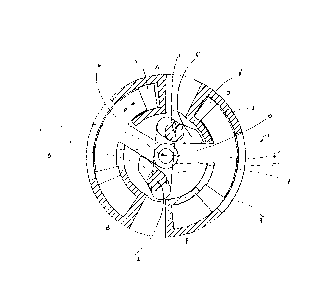
Figure l hence shows in cross-sectional view the internal
parts of an engine l of a first embodiment of the present
invention. The engine includes a rotatably mounted piston
casing 3. The generally cylindrical piston casing houses a
pair of weights in the form of pistons 4, 4' which are
arranged to reciprocate circumferentially. The pistons 4, 4'
are rotatably mounted about centre E via piston arm members
5, 5'.
Transmission or rocker arms 6, 6' are rotatably mounted about
centres I, the centres being fixed in relation to the piston
casing. Each of the arms 6, 6' comprises an engagement
portion arranged to slidingly engage a suitable surface on
the piston arm members 5, 5'. Centres I are generally
diametrically opposed about the centre E.
The transmission arms 6, 6' are connected by way of a
connecting rod 7, which is rotatably mounted at its ends to
a portion of each transmission arm that extends from its
respective centre I on the other side of the engagement
portion. In other words, the transmission arms are arranged
CA 02248719 1998-09-04
PCT/GB97/00621
Wo97/33073
-- 6
to act generally as levers transferring the rotational
movement of the piston arm members into a linear movement of
the connecting rod. The centres I act in this respect as
fulcrum points.
Rotation of, for example, transmission arm 6 about its centre
results in rotation in the opposite direction of transmission
arm 6', with consequential forces being applied by and to the
respective piston arms members 5, 5'. Each piston therefore
moves in a predetermined manner within the piston casing in
relation to the other piston.
The operation of the engine is as follows. In Figure l,
piston 4 at point A is about to undergo combustion. As the
gases within the piston cylinder are ignited, the piston head
is forced in an anti-clockwise direction shown by arrow P.
The cylinder casing at point A is at the same time urged in
a clockwise direction, this clockwise movement being the
general movement derivable from the engine. The weight of
each piston relative to the cylinder casing is formulated
appropriately to ensure a correct operation of the engine. In
general terms, the pistons are comparatively heavy and the
cylinder casing is relatively light.
Piston 4 is thus caused to move anti-clockwise within the
piston cylinder towards the point B. At the same time, by way
of piston arm member 5, and transmission arm 6, the
connecting rod 7 is provided with a linear movement which in
turn causes a rotational movement of transmission arm 6'. The
rotational movement of arm 6' results in the piston arm
member 5' and thus piston 4' being urged to rotate about
centre E in a clockwise direction from position D to position
F.
At point D, the piston 4' is at the end of its combustion
stroke. The clockwise movement imparted to piston 4' will
move it to its combustion point F. Thus, the power stroke of
CA 02248719 1998-09-04
W097/33073 PCT/GB97/00621
-- 7
piston 4 causes piston 4' to move to its combustion point, in
so doing going through its induction and compression strokes.
Referring to Figure 2, once the piston 4' has reached the
combustion point F, it is ready to undergo combustion,
whereby it will be accelerated relative to the cylinder
casing back towards point D. At the same time piston 4 will,
by way of the transmission arms and piston arm members, be
urged from.point B back towards its combustion point A.
By way of this arrangement the piston casing gains an overall
clockwise rotation, which can be taken from the engine via
central shaft 10 fixed relative to the piston casing. The
engine (the piston casing) is thus driven in a clockwise
direction as a consequence of the inertia transfer of energy
from each 'heavy' piston to its respective 'light' cylinder.
Negative forces that tend to oppose rotation of the engine
can be dissipated in a linear, outward direction through
centres I.
Figures 3 to 5 concern a second embodiment of the present
invention. The major difference between the embodiment of
Figures 1 and 2 and that of Figures 3 to S is that the latter
embodiment has two axially aligned piston sets 14, 14'
received in respective piston casings 13.
As shown particularly in Figure 4, each piston set comprises
a pair of diametrically opposed piston heads 19 and 20. The
"top" piston heads are provided on a drive plate 21 which is
fixed relative to output shaft 22.
The coupling means between the piston sets includes
transmission arms 16, 16', shaft members 17 and 17' and
connecting member 23.
Bearing members 24 ensure low friction rotation of the output
shaft 22.
. , . . . ~, . . _
CA 02248719 1998-09-04
W O 97/33073 PCT/GB97/00621
-- 8
operation of the engine is very similar to that of the
embodiment of Figures 1 and 2. The difference is that rather
than a single piston undergoing combustion at any one time,
in this embodiment pairs of piston heads from the same set
undergo combustion together.
For example, referring to Figure 5A, top piston heads 19 are
about to undergo combustion. On combustion, piston set 14 is
hence driven in an anticlockwise direction as shown by arrow
P. The top casing at points A is at the same time urged in a
clockwise direction, this clockwise movement being the
general movement derivable from the engine via shaft 22.
Again, the piston set is comparatively heavy and the piston
casing is relatively light.
Piston set 14 is thus caused to move anti-clockwise within
the piston casing so that the piston heads 19 move towards
the points B. At the same time, by way of transmission arm 16
and shaft member 17, the connecting rod 23 is provided with
a linear movement which in turn causes a rotational movement
of shaft 17' and transmission arm 16'. The rotational
movement of arm 16' results in piston set 14' being urged to
rotate about centre E in a clockwise direction so that the
piston heads 20 move to their combustion points.
Once piston heads 20 of piston set 14' have reached their
combustion points, they are ready to undergo combustion,
whereupon they will be accelerated anticlockwise relative to
piston casing 13. At the same time piston set 14 will be
urged clockwise from points B back towards combustion points
A.
By way of this arrangement the piston casing 13 gains an
overall clockwise rotation. The engine is thus driven in a
clockwise direction as a consequence of the inertia transfer
of energy from each 'heavy' piston to the respective 'light'
cylinder. Negative forces that tend to oppose rotation of the
CA 02248719 1998-09-04
PCT/GB97/00621
W097/33073
g
engine can be dissipated in a linear, outward direction
through centres I as shown by arrows N in Figures 5A to 5C.
The use of diametrically opposed piston sets enhances the
balance and hence reliability of the engine.
The engine works therefore through the principle of firing
relatively heavy solid construction pistons in a combustion
process. This construction allows free heavy pistons to be
the only combustion driven parts from one combustion cycle to
the next. Unlike conventional internal combustion engines,
there is no process of bringing the pistons to a halt through
mechanical means as such in preparation for combustion.
During each combustion cycle, the non-combusted piston set is
effectively catching up within the piston casing to the
combustion point of its respective piston cylinder.
As the pistons are relatively heavy, they can be made of
stronger and stiffer materials. Such stronger pistons will
enable the use of greater pressures so as to increase the
relative volumetric potential of the engine. The pistons will
also be more resilient against piston twist or slap.
For added work efficiency, the engine components optimally
have aerodynamically formed lead edges so as to reduce drag.
By virtue of its arrangement, the engine is free running. The
cylinder is arranged to rotate freely and for operation the
engine does not require a fixed point from which to create
drive. This greatly simplifies the engine and reduces the
likelihood of failure due to wear.
The engine may be supplied with fuel/air and have exhaust
products removed by any suitable method. However, for
example, the fuel/air mixture may be provided and exhaust
. _ . , .
CA 02248719 1998-09-04
PCT/GB97/00621
W097/33073
-- 10 --
products may be removed by way of transfer ports provided in
the cylinder casing.
The engine components may be made from any suitable
materials, such as metals, metal alloys, ceramics, plastics
etc. Conventional cooling systems may be incorporated into
the engine as desired.
It will be understood that the embodiment illustrated shows
an application of the invention in one form only for the
purposes of illustration. In practice, the invention may be
applied to many different configurations. The detailed
embodiments being straight forward for those skilled in the
art to implement.
For example, rather than a pair of piston cylinder
combinations, any suitable number may be used as required.
Whilst the coupling means is shown as a lever arrangement,
other arrangement may of course be used, for example gears
and/or chain drive means.
The engine need not be limited to the field of internal
combustion engines. For example, it could also be configured
as a compressed air/bounce chamber flywheel engine.
.. . ..