Note : Les descriptions sont présentées dans la langue officielle dans laquelle elles ont été soumises.
CA 02249280 1998-09-1
-r
4 . -- 1 --
Installation for the storage of objects,
in particular for boats
The invention relates to installations for the storage of
objects, in particular for boats. Installations for the
storage of boats are known from documents US-4 640 214 and
DE 39 37 09~ A1. However, the present invention shows sig-
nificant advantages in comparison to the inventions de-
scribed in the above mentioned documents, these advantages
o are described in the following description; especially the
movable storage elements
Such installations serve for example for the storage of
boats, such as sailing yachts, motor boats or similar. For
example in autumn the boat is removed from the water with a
trailer and is transported into a hall or a similar place
of storage and left there for storage over the winter In
such halls or places of storage, the boats can be main-
tained, repaired and refurbished.
The disadvantage of this practice is that the trailer with
which the boats are transported and stored takes up very
much space in the hall For this reason, it is common prac-
tice today for yachts when being stored in halls to be
25 taken from their trailer, placed on their keels and to be
supported using lateral supports in order to accommodate
the ~aximum number of boats in the hall
Boat builders and boat wharves in particular have major
30 problems with storage space as they are often located close
to the water. They have far too little space, for example,
when the boat~s are removed ~rom the water over winter and
are stored to be able to easily carry out repairs. It is
CA 02249280 1998-09-1
-- 2
also disadvantageous that if work is carried out in the
boat storage halls, then the other yachts become signifi-
cantly dirty. For this reason, they must be specially cov-
ered.
s
The present invention is based on the problem of solving
the above mentloned disadvantages and on creating an in
stallation with which numerous boats, but also other ob-
jects can be stored quickly, and most importantly, requir-
- 1o ing little space Easy access to the stored boats or the
stored objects should be possible.
- This problem is solved by arranging numerous cells in a
honeycomb fashion next to and / or above each other
The present invention permits numerous boats to be stored
preferably in hexagonal cells which are stacked in a honey-
comb fashion next to and above each other. The individual
cells are hereby formed in any desired length, such that
when necessary, two boats can be inserted into the tubular
cells using the appropriate storage trolleys. Also an ar-
rangement of the cells in many levels of the individual
cells stacked upon each other is desirable
In the individual cells, storage trolleys are mounted which
are fitted with slots and guide rails, into which the stor-
age trolleys can be driven These storage trolleys serve
the support and easy handling of objects, in particular
boats.
io
In order to support the boat in position, lateral brackets
with arms co,nnected to them are mounted on to a base plate
on the storage trolley, which support the boat using so
. . .
CA 02249280 1998-09-15
called adjustable supports. These supports are held by ad-
justable struts, so that an exact positioning of the sup-
ports on the hull of the boat is possible. To ensure that
the surface of the hull is not damaged, padded blocks are
provided on the ends of the supports that support the boat.
In the case of a sailing yacht, the keel stands preferably
on the base plate of the storage trolley, so that most o~
the weight, respectively the centre of gravity is carried
by the base plate. In order to accommodate the mast and the
o boom on the storage trolley, mounting blocks or similar are
provided if necessary.
To extract a boat out of such a cell, an appropriate lift-
ing device is provided which is fitted with a lift suitable
for receiving the storage trolley. This lifting device is
raised to the height of the cell so that the storage trol-
ley complete with the boat can be driven onto the lifting
device, which then transports the storage trolley and the
boat to the working area. Here, it is also conceivable that
a crane lift the boat on the storage trolley from the lift-
ing device onto a trailer.
That the individual cells can be locked up using locking
mechanisms, gates, or similar items, which are not shown in
the drawings, also lies within the scope of the present in-
vention. In addition to this, lying within the scope of the
present invention is that different arrangements of cells
beside each other and above each other, which form a unit
or a hall, are possible, whereby it is particularly advan-
tageous if a single lifting device can be driven along adriveway and that on both sides of the lifting device cells
are arranged so that a large number of boats and other ob-
jects can be stored
. _ _
CA 02249280 1998-09-1~
Other polygon cell cross sections lie also within the scope
of the present invention for the storage , for example, of
boats or other objects It is however to be especially em-
phasised that the present preferred hexagonal structure hasproved to be the only static self supporting structure
With the present invention an installation has been created
which makes it possible to store a large number of boats
within a very limited space. Besides this, every boat or
every cell respectively is easily and quickly accessibIe,
so that also in the case of repai~s or ~aintenance every
boat can be removed from its cell for this purpose Should,
for example, all the boats be in the water, then other ob-
jects can be stored in the cells.
Further advantages, characteristics and details of the in-
vention can be gathered from the following description of
the preferred embodiment of the invention as well as on the
basis of the drawings which show in
Fig. 1 a front view of the installation according to the
invention for the storage of objects, especially
boats;
Fig. 2 an enlarged view of a single cell of the instal-
- lation according to Fig. 1, complete with con-
tents;
Fig. 3 a view of a further embodiment of the cell ac-
cording to Fig. 2 without contents;
Fig. 4 a schematic view of thè lifting device
Fig. 5 a further embodiment of the lifting device ac-
cording to Fig. 4;
CA 02249280 1998-09-1
-- 5
Fig 6 a schematic side view of a possible arrangement
of cells and lifting devices;
Fig. 7 a view of a possible arrangement of cells and
lifting devices according to Fig. 6
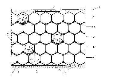
According to Fig. 1, the installation R according to the
invention for the storage of objects, in particular boats,
shows numerous cells 1 These cells 1 are preferably formed
as hexagons and are arranged next to and above each other
o as shown, so that a honeycomb structure is formed Here, i~
necessary, stabilising blocks 3, which are firmly attached
to the ground 2, are arranged next to each other, whereby
between two stabilising blocks 3 a cell 1 is placed as
shown
Each single honeycomb formed cell 1 is provided with a tri-
angular base element 4 from which walls 5.1, 5.2 rise ver-
tically on which a symmetrical to the base element 4 trian-
gular roof element 6 connects. The individual cells 1 are
in the longitudinal direction tubular in form whereby, if
necessary the back wall is closed ln order to achieve a
greater torsional stiffness
As shown in Fig 1, the individual cells 1 are arranged in
several layers El to E5 above each other, each layer being
shifted in respect to it's neighbour. Due to the honeycomb
arrangement of the individual cells 1 the installation R
attains a very high stability in order to support high
loads. Finally, the installation R can be covered by a hall
roof 7
.. . .
CA 02249280 1998-09-1~
It is ensured due to this special arrangement that a large
nu~ber of objects, especially boats 8, can be stored in the
individual cells 1 in the smallest possible space
s According to Fig 2, a beam 9 is placed approximately in
the middle of the triangular section of the base element 4.
This beam 9 displays guide slots 10.1, 10 2, which prefera-
bly extend over the entire length of the cell The beam 9
is preferably firmly attached to the base element 4
Further to this, in the corner regions 11 1, 11.2 between
base element 4 and wall 5 1 and base element 4 and wall 5 2
respectively guide rails 12.1, 12 2 are placed which extend
over the entire length of the cell 1. Here the guide rails
12 1, 12.2 extend over the corner regions 11.1, 11 2 which
join the sides 13 1, 13.2 of the base element 4 with the
walls 5 1, 5.2
A storage trolley 14 according to the invention is applied
in the cell 1 in a insertable and extractable manner.
The storage trolley 14 displays a base plate 15 on which
the keel 16 of the boat 8 is supported. Beneath the base
plate 15 transport rollers 17.1, 17.2 spaced at a certain
distance apart are provided which ~it in the guide slots
10.1, 10.2 of the beam 9. The storage trolley 14 is guided
in the guide slots 10 1, 10.2.
Parallel lateral brackets 18.1, 18 2 extend from the base
plate 15 running appropriately to suit the sides 13.1, 13 2
until they reach the corner regions 11 1, 11.2 and then
they are bent,upward5 and run parallel to the walls 15.1,
15.2 as short arms 19.1, 19.2.
CA 02249280 1998-09-15
-- 7
The lateral brackets 18 1, 18 2 and the arms 19.1, 19 2 are
provided with rotary rollers 20 in the corner regions 11 1,
11 2 which face outwards. These rollers 20 support the
storage trolley 14 against the guide rails 12 1, 12 2 In
this ~anner an exact positioning and guiding is achieved in
order to insert or extract the storage trolley 14 into or
out of the cell 1.
To secure the boat 8 in the storage trolley 14 from tipping
over it is preferred that the adjustable supports 21 1,
: 21.2 be mounted to the arms 19.1, 19.2 forming an articu-
lated joint On the opposite ends of the adjustable sup-
ports 21.1, 21 2 blocks 22.1, 22.2, which support the hull
of the boat, are mounted forming artlculated joints.
The supports 21.1, 21.2 formed, especially in the case of
sailing yachts, to suit the form of the hull and the appro-
~ priate length of the keel 16. In addition, the supports
21 1, 21.2 provided with adjustable struts 23.1, 23.2 whlch
are connected to the lateral brackets 18 1, 18.2 at articu-
lated joints. Therefore, the position of the supports 21.1,
21 2 can be appropriately adapted to accommodate, for exam-
ple, very narrow or very wide hulls of boats. The supports
21 1, 21.2 and also the struts 23.1, 23.2 can hereby be ad-
justed mechanically, or also pneumatically, hydraulically
or electrically
Preferably the base plate 15 is approximately as long as
the cell 1 or as long as the hull o~ the boat whereby at
the front end of the base plate in the bow region of the
boat, which is not shown on the drawings, appropriately
formed lateral brackets are provided in si~ilar fashion to
CA 02249280 1998-09-1~
the stern region of the boat Therefore the hull of the
boat 8 is supported by at least four supports This type of
storage is also suitable for motor boats, whereby it is
also planed in this instance to adapt the supports 21 1,
21 2 to suit the hull and if necessary to make them lower.
For this reason, the supports 21 1, 21.2 and the struts
23 1, 23.2, which are mounted on the arms 19 1, 19.2 or the
lateral brackets 18.1, 18.2 respectively, can be fitted at
different positions.
Mounting blocks 24 are arranged, in particular for sailing
yachts, on the storage trolley 14 onto which, for example,
a ~ast 25 or a boom 26 can be laid down.
A further embodiment of the present invention according to
Fig. 3 shows the storage trolley 14 as displayed in Fig. 2
without supports 21.1, 21.2 and struts 23.1, 23.2 On the
other hand, a pallet 27 is placed between the arms 19.1,
19.2 on which different types of objects can be laid down.
I'his is in particular the case when, for example, the boats
are in the water and the cells 1 can be used as storage for
common types of goods.
.
In order to be able to extract the storage trolley 14 for
the accommodation of a boat from the cell 1 in one of the
levels, E1 to E5, a llfting device 28, which is shown ln
Fig. 4 and 5, must be inserted into the cell 1 to lift up
the storage trolley 14. The lifting device 28 displays
nelghbouring guide columns 29 1, 29 2 which are connected
to each other and serve to accommodate a lift 30 which is
provided between them.
~ ,
CA 02249280 1998-09-15
g
The lift 30 is adjustable in it's height along the guide
colu~ns 29 1, 29 2 as indicated by the double arrows X The
lift 30 is provided with a beam 9.1, which matches the beam
9 of the cell 1, as well as being provided with sides
s 13.1', 13.2' and the guide rails 12.1', 12 2', which are
identical to the corresponding elements in the cell 1. For
this reason, a transfer of the storage trolley 14 from the
cell 1 to the lift 30 is achievable without difficulties.
o Further, the lifting devlce 28 can be driven backwards and
forwards along a rail system 31, which runs on the floor 2
Consequently, every possible cell 1 can be accessed The
li~t 30 is then driven to a ~oint opposite the base element
4 o~ the cell 1 and subsequently, the storage trolley 14 is
S driven out of the cell 1 onto the lift 30 of the lifting
device. Also in reverse if necessary, a loaded storage
trolley 14 can be driven into a cell 1. In order to prevent
the lifting device 28 from tipping over in such situations,
due to lnstability, several guide columns can be arranged
behind each other.
Fig. 5 shows another lifting device 28 1 with only one
guide column 29.1 on which the lift 30 can be driven This
is adequate ~or lighter boats 8.
~ig 6 shows an installation with cells arranged above each
other which are~arranged on both sides of the lifting de-
vice driveway 31 Using the lift 30, whose height can be
adjusted, the individual cells l can be loaded or unloaded.
In order to protect the individual cells from the weather,
the cells can be covered by the side walls 33, 34 and the
roof 7.
CA 02249280 1998-09-15
-- 10
As shown in Fig. 7, the individual cells 1 grouped together
in regions on both sides of the lifting device driveway 32
whereby it is also intended that additional working areas
36, 37, are provided in order to repair or maintain boats
or other objects.
An especially ef~ective embodiment of the invention is
given when for example the lifting device runs directly -
into the water and a boat ramp is provided in order to
o transport boats directly out o~ the water into the individ-
ua~ cells.