Sélection de la langue

Search

Sommaire du brevet 2250972 

Énoncé de désistement de responsabilité concernant l'information provenant de tiers

Une partie des informations de ce site Web a été fournie par des sources externes. Le gouvernement du Canada n'assume aucune responsabilité concernant la précision, l'actualité ou la fiabilité des informations fournies par les sources externes. Les utilisateurs qui désirent employer cette information devraient consulter directement la source des informations. Le contenu fourni par les sources externes n'est pas assujetti aux exigences sur les langues officielles, la protection des renseignements personnels et l'accessibilité.

Disponibilité de l'Abrégé et des Revendications

L'apparition de différences dans le texte et l'image des Revendications et de l'Abrégé dépend du moment auquel le document est publié. Les textes des Revendications et de l'Abrégé sont affichés :

  • lorsque la demande peut être examinée par le public;
  • lorsque le brevet est émis (délivrance).
(12) Demande de brevet: (11) CA 2250972
(54) Titre français: VAPORISATEUR EN POSITION DEBOUT OU INVERSEE
(54) Titre anglais: UPRIGHT/INVERTED SPRAYER
Statut: Réputée abandonnée et au-delà du délai pour le rétablissement - en attente de la réponse à l’avis de communication rejetée
Données bibliographiques
(51) Classification internationale des brevets (CIB):
  • B05B 11/02 (2006.01)
(72) Inventeurs :
  • PARES MONTANER, PEDRO (Espagne)
  • COSTA QUINTAS, LLUIS (Espagne)
(73) Titulaires :
  • MONTURAS, S.A.
(71) Demandeurs :
  • MONTURAS, S.A. (Espagne)
(74) Agent:
(74) Co-agent:
(45) Délivré:
(22) Date de dépôt: 1998-10-21
(41) Mise à la disponibilité du public: 1999-04-24
Licence disponible: S.O.
Cédé au domaine public: S.O.
(25) Langue des documents déposés: Anglais

Traité de coopération en matière de brevets (PCT): Non

(30) Données de priorité de la demande:
Numéro de la demande Pays / territoire Date
97/02196 (Espagne) 1997-10-24

Abrégés

Abrégé français

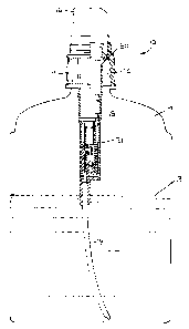
La présente invention fait état d'un vaporisateur à poussoir manuel pour liquides pouvant fonctionner en position debout et en position inversée. Le vaporisateur comprend un adaptateur, fixé au corps de la pompe, grâce auquel il peut fonctionner en position debout et en position inversée. L'adaptateur est muni d'un premier et d'un second passages de fluide partant d'une chambre d'adaptateur et allant en directions opposées afin de former respectivement une entrée de liquide provenant du contenant et menant à la chambre, lorsque le vaporisateur est placé en position debout ou inversée, dans laquelle entrée un des passages est exposé à l'air dans le contenant. Les passages se terminent dans la chambre dans des sièges de clapet opposés, en position debout et en position inversée, qui sont commandés par soupape au moyen d'un clapet de retenue à bille unique se déplaçant par gravité.


Abrégé anglais


A manually actuated liquid pump sprayer, capable of being operated in both an
upright position and in an inverted position, includes an adapter attached to its pump
body to effect the upright and inverted spray, the adapter having first and second fluid
passages extending from an adapter chamber in opposite directions for respectively
inletting liquid from the container to the chamber in one of the upright and inverted
positions, and being exposed to air in the container in the other such positions, the
passages terminating within the chamber in opposing upright and inverted valve seats
which are valved controlled by a single gravity shifting ball check valve.

Revendications

Note : Les revendications sont présentées dans la langue officielle dans laquelle elles ont été soumises.


The embodiments of the invention in which an exclusive
property or privilege is claimed are defined as follows:
1. A manually actuated liquid pump sprayer capable of being operated in
both an upright position and in an inverted position, comprising a pump body having
means for mounting the body to a container of liquid to be dispensed, adapter means
mounted to said body for effecting both upright and inverted spray, said adapter means
having first and second fluid passages extending from an adapter chamber in opposite
directions for respectively inletting liquid from the container to the chamber in only one
of the upright and inverted positions, and being exposed to air in the container in the
other of said positions, said passages terminating within said chamber in opposing
upright and inverted valve seats, and said adapter means including a single ball check
valve gravity shifted between said valve seats depending on the upright and inverted
positions of the sprayer for valving off one of said passages when exposed to air in the
container.
2. The sprayer according to claim 1, wherein said adapter means comprises
an adapter body, said first passage including a dip tube mounted to said adapter body
and a groove formed in said adapter body communicating with one of said valve seats
and with said dip tube.
3. The sprayer according to claim 2, wherein said second passage extends
within said adapter body between the other of said valve seats and one end of said
adapter body in the vicinity of said mounting means.
-9-

4. The sprayer according to claim 2, wherein said adapter body comprises an
elongated liner having a first section coupled to said pump body, an internal cylinder
coaxial with a second section of said adapter body, said cylinder defining said adapter
chamber and being coupled to a valve controlled inlet passage of said pump body, a
first of said valve seats projecting into said adapter chamber from a wall of said
cylinder, said adapter body further comprising a hollow insert element having a first
section extending into said second section, said first section of said element supporting
a second of said valve seats which projects into said adapter chamber.
5. The sprayer according to claim 4, wherein said first section of said liner has
an internal longitudinal first groove forming together with said pump body a portion of
said second passages, said first portion of said insert element having an external
longitudinal second groove forming together with said liner another portion of said
second passage and said cylinder having an external longitudinal third groove forming
together with said first section of said insert element a portion of said first passage.
-10-

Description

Note : Les descriptions sont présentées dans la langue officielle dans laquelle elles ont été soumises.


CA 022~0972 1998-10-21
BACKGROUND OF THF INVF~ITION
This invention relates to a manually actuated liquid pump sprayer capable of
being operating in both an upright position and in an inverted position by the provision
of first and second oppositely extending fluid flow passages extending within the liquid
in the container to which the pump sprayer is mounted in one of the upright and
inverted positions, and extending into air in the container and the other of such
positions.
Pump dispensers having only a single fluid flow passage comprising a dip tube
extend from the pump into the liquid at the bottom of the container such that liquid is
suctioned into the pump sprayer during its operation so long as there is liquid in the
container and while the container is held in a position in which its bottom is located
substantially below the pump sprayer.
Such known dispensers, however, are generally incapable of being operated in
an inverted position as when the dip tube is no longer in communication with the liquid
in the container.
U.S. patent 4,277,001 discloses a manually actuated pump sprayer adapted for
upright and inverted spray by the provision of a three-way valve assembly mounted to
the sprayer. Such assembly is, however, of complex structure requiring ball check
valves associated with both oppositely extending fluid flow passages.
SUMMARY OF THE INVENTION
It is an object of the present invention to provide a pump sprayer capable of
upright and inverted spray by the provision of an adapter which is of simple
-2-

CA 022~0972 1998-10-21
construction, is highly economical and avoids the known disadvantages of the prior art.
According to the invention the adapter has confronting upright and inverted valve seats
located within an adapter chamber in communication with the pumping mechanism,
there being a single gravity shifting ball check valve provided for both valve seats.
S The adapter for the manually actuated pump sprayer according to the invention
is a two-part structure comprising an elongated liner mounted to the pump body of the
sprayer, and a hollow insert element coupled to the liner and extending into a terminal
end of the liner. The liner has an inner elongated coaxial cylinder which defines an
adapter chamber and which is coupled to a valve controlled inlet passage of the pump
body. A first of the valve seats projects into the adapter chamber from a wall of the
cylinder. The insert element supports a second of the valve seats which projects into
the adapter chamber.
Further according to the invention the liner of the two-part adapter has an
internal longitudinal first groove which forms a portion of the second passage together
with the pump body. The insert element has an external longitudinal second groove
which forms another portion of the second passage together with the liner, and the
cylinder has an external longitudinal third groove which forms a portion of the first
passage together with the insert element.
Other objects, advantages, and novel features of the invention will become more
apparent from the following detailed description of the invention when taken in
conjunction with the accompanying drawings.

CA 022~0972 1998-10-21
BRIEF DESCRIPTION OF THF DRAWINGS
Fig. 1 is a side elevational view, partly in section, of the uprighVinverted adapter
according to the invention attached to a manually actuated pump sprayer mounted on a
container of liquid shown in an upright position;
S Fig. 2 is a view similar to Fig. 1 showing the container and pump in an inverted
position;
Fig. 3 is a vertical sectional view of the adapter according to the invention shown
mounted to the pump body in an upright position.
Fig. 4 is a view similar to Fig. 3 in the inverted position;
Fig. 5 is a vertical sectional view of the elongated liner forming one part of the
adapter according to the invention;
Fig. 6 is a top plan view of the liner of Fig. 5;
Fig. 7 is a vertical sectional view of the other part of the adapter of the invention
in the form of a hollow insert element;
Fig. 8 is a cross-sectional view taken substantially along the line 8-8 of Fig. 7;
and
Fig. 9 is a top elevational view of the insert element of Fig. 7.
I~ETAILED DFSCRIPTION OF THF INVFNTION
A manually actuated pump sprayer of any known type, such as the finger
actuated pump disclosed in U.S. patent 5,064,105 commonly owned herewith, is
generally designated 10 in Fig. 1 has an internally threaded closure cap 11 to facilitate
mounting the pump sprayer to a container 12 of liquid 13 to be dispensed. The pump
-4-

CA 022~0972 1998-10-21
sprayer mounted to an externally threaded neck 14 of the container, further includes a
pump body 15 which extends into the container interior, and a dispenser head 16
having a discharge orifice (not shown) through which liquid product is sprayed upon
depression of the head usually by the finger of the user for actuating the pumping
5 mechanism, as disclosed in the aforementioned patent. Other fingertip sprayers are
capable of being utilized together with the adapter according to the invention.
As more clearly shown in Figs. 3 and 4, the terminal end of the pump body which
extends into the container forms an inlet passage 17, as is typical for fingertip pump
sprayers of this type, which is valve controlled by, for example, a ball check valve 18
10 although other inlet valving may be provided. A dip tube, such as 19, would normally
depend directly from inlet passage 17 except that, in accordance with the invention, the
dip tube extends from an uprighVinverted adapter provided according to the invention,
generally designated 21. The adapter comprises a two-part structure shown in detail in
Figs. 5 and 7, and is shown assembled together in Figs. 1 to 4.
Turning to Fig. 5 an elongated liner generally designated 22 is shown as forming
one part of the adapter, the liner having a first section 23 of a shape complementary to
that of pump body 15 such that the liner can be conveniently attached thereto and be
secured by a friction fit. The liner has an internal cylinder 24 which defines an adapter
chamber 25, the cylinder being mounted within the liner as by a plurality of spaced
20 radial arms 26 more clearly shown in Fig. 6. And as shown in Fig. 3 the cylinder is
telescoped over sleeve 26 of the pump body, such that adapter chamber 25
communicates with inlet passage 17 of the pump.
-5-

CA 022~0972 1998-10-21
As shown in Figs. 1 to 4, the adapter comprises a pair of confronting, upright and
inverted valve seats, a first valve seat 27 being shown in Fig. 5 as projecting into
adapter chamber 25 from a wall of cylinder 24.
First section 23 of liner 22 has an internal longitudinal first groove 28 which
5 together with pump body 15 forms a portion of a second fluid flow passage extending
into the adapter chamber which will be described more fully hereinafter. And, cylinder
24 has an external longitudinal third groove 29 extending between free end 31 of
cylinder 24 and a transverse port 32 leading to valve seat 27.
The second part of the adapter according to the invention comprises a hollow
insert element generally designated 33 in Figs. 7, 8 and 9. The insert element has a
first cylindrical section 34 which extends into second section 35 of liner 22 so as to be
frictionally coupled together with the liner as shown in Figs. 3 and 4. First section 34 of
the insert element supports a second of the valve seats 36 which projects into adapter
chamber 25.
First section 34 of insert element 33 has an external longitudinal second groove
37 more clearly shown in Figs. 8 and 9, the groove forming a second fluid flow passage
30 together with the liner when assembled. Second groove 37 extends from the
terminal end of portion 34 to port 38 which communicates with valve seat 36. The
insert element further has an external sleeve 39 into which one end of dip tube 19 is
20 fitted for suspending the dip tube inside the container.

CA 022~0972 1998-10-21
When parts 22 and 33 are assembled together groove 29 forms together with
portion 34 of the insert element a portion of first fluid flow passage 20 which is in
communication with the interior of the dip tube.
In operation, with the pump and container in a substantially upright position as
5 shown in Figs. 1 and 3, product is suctioned into the pump chamber of the pump (not
shown but downstream of valve 18) during pumping operation as product is suctioned
up the dip tube and into adapter chamber 25 and up through inlet passage 17. A single
ball check valve 41 has gravity shifted between the confronting valve seats 27 and 36
such that in the upright position valve 41 is seated at its valve seat 36 for valving
10 second fluid flow passage 30 closed. Thus although the second fluid passage is in
communication with the air inside the container, as the passage terminates at 50 in the
vicinity of container closure 11, air is prevented from being suctioned into adapter
chamber 25 during the pump suction strokes. While in the upright position the pump
operates in a normal manner as a standard pump.
With the pump in a substantially inverted position shown in Figs. 2 and 4, the dip
tube and its fluid flow passage 20 now communicate with the air in the container, while
the second fluid flow passage 30 is in communication with the liquid in the container.
The ball check valve 41 falls by gravity to its seat 27 to thereby valve air passage 20
closed while product is suctioned into the pump chamber via the adapter chamber
20 through passage 30 to facilitate carrying out the pumping operation as in any normal
manner.

CA 022~0972 1998-10-21
From the foregoing it can be seen that a simple and economical yet highly
effective adapter for a manually actuated pump dispenser has been devised which
renders the dispenser capable of both upright and inverted spray without leakage and
without the need for a complex valving assembly. Moreover the two parts of the
S adapter can each be molded easily and economically by known plastic molding
techniques.
Obviously many modifications and variations of the invention are made possible
in the light of the above teachings. It is therefore to be understood that within the scope
of the appended claims the invention may be practiced otherwise than as specifically
10 described.

Dessin représentatif
Une figure unique qui représente un dessin illustrant l'invention.
États administratifs

2024-08-01 : Dans le cadre de la transition vers les Brevets de nouvelle génération (BNG), la base de données sur les brevets canadiens (BDBC) contient désormais un Historique d'événement plus détaillé, qui reproduit le Journal des événements de notre nouvelle solution interne.

Veuillez noter que les événements débutant par « Inactive : » se réfèrent à des événements qui ne sont plus utilisés dans notre nouvelle solution interne.

Pour une meilleure compréhension de l'état de la demande ou brevet qui figure sur cette page, la rubrique Mise en garde , et les descriptions de Brevet , Historique d'événement , Taxes périodiques et Historique des paiements devraient être consultées.

Historique d'événement

Description Date
Inactive : CIB expirée 2023-01-01
Exigences relatives à la révocation de la nomination d'un agent - jugée conforme 2021-04-01
Inactive : Demande ad hoc documentée 2006-03-23
Demande visant la révocation de la nomination d'un agent 2006-03-14
Inactive : CIB de MCD 2006-03-12
Le délai pour l'annulation est expiré 2001-10-22
Demande non rétablie avant l'échéance 2001-10-22
Réputée abandonnée - omission de répondre à un avis sur les taxes pour le maintien en état 2000-10-23
Inactive : Page couverture publiée 1999-05-24
Demande publiée (accessible au public) 1999-04-24
Symbole de classement modifié 1998-12-17
Inactive : CIB en 1re position 1998-12-17
Inactive : CIB attribuée 1998-12-17
Inactive : Certificat de dépôt - Sans RE (Anglais) 1998-12-01
Demande reçue - nationale ordinaire 1998-11-30

Historique d'abandonnement

Date d'abandonnement Raison Date de rétablissement
2000-10-23

Historique des taxes

Type de taxes Anniversaire Échéance Date payée
Enregistrement d'un document 1998-10-21
Taxe pour le dépôt - générale 1998-10-21
Titulaires au dossier

Les titulaires actuels et antérieures au dossier sont affichés en ordre alphabétique.

Titulaires actuels au dossier
MONTURAS, S.A.
Titulaires antérieures au dossier
LLUIS COSTA QUINTAS
PEDRO PARES MONTANER
Les propriétaires antérieurs qui ne figurent pas dans la liste des « Propriétaires au dossier » apparaîtront dans d'autres documents au dossier.
Documents

Pour visionner les fichiers sélectionnés, entrer le code reCAPTCHA :


Pour visualiser une image, cliquer sur un lien dans la colonne description du document. Pour télécharger l'image (les images), cliquer l'une ou plusieurs cases à cocher dans la première colonne et ensuite cliquer sur le bouton "Télécharger sélection en format PDF (archive Zip)" ou le bouton "Télécharger sélection (en un fichier PDF fusionné)".

Liste des documents de brevet publiés et non publiés sur la BDBC .

Si vous avez des difficultés à accéder au contenu, veuillez communiquer avec le Centre de services à la clientèle au 1-866-997-1936, ou envoyer un courriel au Centre de service à la clientèle de l'OPIC.


Description du
Document 
Date
(aaaa-mm-jj) 
Nombre de pages   Taille de l'image (Ko) 
Abrégé 1998-10-20 1 18
Description 1998-10-20 7 248
Revendications 1998-10-20 2 68
Dessins 1998-10-20 4 99
Dessin représentatif 1999-05-18 1 7
Dessin représentatif 2007-01-11 1 7
Courtoisie - Certificat d'enregistrement (document(s) connexe(s)) 1998-11-30 1 114
Certificat de dépôt (anglais) 1998-11-30 1 163
Rappel de taxe de maintien due 2000-06-21 1 109
Courtoisie - Lettre d'abandon (taxe de maintien en état) 2000-11-19 1 183
Correspondance 2006-03-13 3 116