Note : Les descriptions sont présentées dans la langue officielle dans laquelle elles ont été soumises.
CA 02251881 1998-10-16
WO 97!42368 PCT/CA97/00300
COLLECTION AND DEPOSITION OF CHOPPED FIBROUS STRANDS
FOR FORMATION INTO NON-WOVEN WEBS
OF BONDED CHOPPED FIBERS
TECHNICAL FIELD
The present invention relates in general to the collection of chopped fibrous
materials and, more particularly, to apparatus for collecting chopped fibers
from a source
of such fibers and depositing the chopped fibers on a collection surface to be
processed
into non-woven webs of bonded chopped fibrous materials commonly referred to
as
chopped strand mat. While the invention is generally applicable to a wide
variety of
fibrous materials including mineral and organic fibrous materials, it will be
described herein
with reference to glass fibers for which it is particularly applicable and
initially being
applied.
BACKGROUND OF THE INVENTION
1 S Continuous strands of fibrous material, such as glass filaments, have been
collected and distributed using opposed Coanda effect surfaces to produce mats
of such
material used, for example, for insulation. Examples of such equipment are
disclosed in
U.S. Patents No. 4,300,931; No. 4,466,819; and, No. 4,496,384. Such continuous
strands
typically are handled wet since they are coated with binder or sizing which is
sprayed or
otherwise applied to the strands prior to the strands being passed to the
Coanda effect
surfaces.
Unlike these continuous fibers, chopped fibers are dry such that there can
be a substantial build up of static electricity during their processing.
Accordingly, when
chopped fibers are handled, equipment for suppressing or dissipating static
electricity is
normally provided. Unfortunately, static suppression equipment adds expense to
equipment handling dry chopped fibers and can cause problems of its own in
terms of
maintenance.
Even so, non-woven webs of bonded chopped glass, i.e., chopped strand
mat, have been produced for many years. An initial step in that production is
to collect the
chopped glass and deposit it onto a moving collection surface with the
resulting mat of
chopped glass being processed to produce the chopped strand mat. Choppers are
positioned over a forming hood which surrounds the collection surface with the
choppers
CA 02251881 2004-07-27
providing chopped glass to the forming hood through openings in the top of the
hood to direct a
chopped glass stream toward the collection surface. Air nozzles are angled
into the glass stream
in an attempt to disperse the glass stream.
The amount of glass strand input to each of the choppers is adjusted and the
nozzles
bent in an attempt to evenly distribute the chopped glass on the collection
surface. The collection
surface is foraminous and has air drawn through it to assist in the even
distribution of the chopped
glass and to draw the glass to the collection surface. Unfortunately, these
efforts to achieve uniform
fiber distribution on the collection surface are not always successful.
There is, thus, a need for improved apparatus for collecting chopped fibers
from a
source of such fibers and depositing the chopped fibers on a collection
surface such that the
chopped fibers are evenly distributed and thereby better able to be processed
into chopped strand
mat. Preferably, such apparatus would overcome problems with turbulent air
flow in the forming
hood and static electricity which are associated with existing chopped fiber
handling.
SUMMARY OF THE INVENTION
Accordingly, an inlet cone, an air amplifier and an outlet cone can be
associated
with one another to form an air cannon which receives chopped fibers and which
can forcefully
deposit the chopped fibers on a collection surface or web moving beyond an
outlet end of the
outlet cone. A binder can be applied to the resulting mat of chopped fibers,
the binder may be
activated by the application of energy such as heat with the resulting treated
mat being
compacted, cooled and rolled up to form a chopped strand mat package. For wide
mats, one or
more banks each made up of at least one and preferably a plurality of air
cannons can extend
across the moving collection web. The air cannons of a bank containing a
plurality of air
cannons are preferably alternately directed up-line and down-line of the web
to reduce
interference between the air cannons which can also be individually adjusted
to vary the aimed
direction of the air cannons across the web. The air cannons can forcefully
direct chopped fibers
to the web and thereby overcome air turbulence within the forming hood and
forces due to
static electricity.
In accordance with one aspect of the invention, there is provided an air
cannon
for collecting chopped fibrous material and depositing received chopped fibers
on a moving
-2-
CA 02251881 2004-07-27
collection surface comprises an air amplifier defining a passage therethrough
and having an
inlet and an outlet. The air amplifier is driven by compressed air which
enters the passage of the
air amplifier through an air orifice. An outlet end of an inlet cone is
positioned adjacent the
inlet of the air amplifier with an inlet end of the inlet cone receiving
chopped fibers and
directing them to the air amplifier. An inlet end of an outlet cone is
positioned adjacent the
outlet of the air amplifier and an outlet end of the outlet cone directs
chopped fibers onto the
moving collection surface. In a preferred embodiment of the invention, the
inlet and outlet
cones are shaped as a frustum of a circular cone, and the inlet end of the
inlet cone is larger than
the outlet end of the inlet cone while the outlet end of the outlet cone is
larger than the inlet end
of the outlet cone.
The air amplifier has a minimum inside diameter and the outlet end of the
inlet
cone preferably is sized between about 0.75 times the minimum inside diameter
and 1.25 times
the minimum inside diameter. The outlet end of the inlet cone preferably is
also spaced from
the air orifice by a distance ranging from about 1132 inch (0.8 mm) to about
%z inch (12.7 mm).
The outlet of the air amplifier has a minimum outside diameter and the inlet
end of the oulet
cone can be sized between about 1.00 times the minimum outside diameter and
1.25 times the
minimum outside diameter. Axes A of symmetry of the air amplifier, the inlet
cone and the
outlet cone can be in substantial alignment with one another, preferably with
the axes A of
symmetry of the air amplifier, the inlet cone and the outlet cone being in
alignment with one
another within about 0.125 inch. For proper ingestion of the chopped fibers by
an air cannon,
the substantially aligned axes A of symetry of the inlet cone, the air
amplifier and the oulet cone
are within 45° of a velocity vector of chopped fibers as the fibers are
discharged from a source
of chopped fibers.
In accordance with another aspect of the invention, apparatus for collecting
chopped fibrous material and depositing received chopped fibers on a moving
collection surface
comprises at least one bank of air cannons mounted across the moving
collection surface. The
bank comprises at least one and preferably a plurality of air cannons which
are positioned
relative to one another to reduce interference therebetween. In a working
embodiment of the
invention, to reduce interference between adjacent air cannons of a plurality
of air cannons, the
apparatus fizrther comprises a plurality of generally L-shaped rods for
mounting the plurality of
air cannons. The L-shaped rods are formed to direct alternate air canons up-
line and down-line
relative to movement of the moving collection
-3-
CA 02251881 1998-10-16
WO 97/42368 PCT/CA97/00300
surface. The L-shaped rods have generally horizontal legs mounted to a support
frame
and generally vertical legs with the air cannons secured thereto. To effect
the alternating
up-line/down-line direction of the air cannons, the L-shaped rods have
alternating acute
and obtuse angles between their generally horizontal and generally vertical
legs.
The generally horizontal legs of the mounting rods are mounted for rotation
in the support frame for movement of the air cannons in the cross direction of
the moving
collection surface. Adjustment arms are secured to the generally horizontal
legs for
adjusting the rotational position of the generally horizontal legs of the L-
shaped rods and
hence the vertical legs and air cannons secured thereto. Locking devices are
associated
with the adjustment arms for locking the adjustment arms and hence the
generally
horizontal legs in preferred rotational positions. In a working embodiment,
the locking
devices comprise eye bolts passing through oblong holes in the adjustment arms
and cam
levers pivotally mounted to the eye bolts. The cam levers are moved to one
position to
release the adjustment arms for movement of the adjustment arms within limits
defined by
the oblong holes and the eye bolts. In a locked position, the cam levers
secure the
adjustment arms to the support frame for maintaining adjustments of the
mounting rods
and thereby cross direction positioning of the air cannons.
In accordance with yet another aspect of the invention, a process for
forming a chopped strand mat comprises the steps of chopping strands of
fibrous
material; passing chopped strands through at least one air cannon to disperse
the chopped
strands and force the chopped strands against a moving collection surface;
applying a
binder to the chopped strands; applying energy to activate the binder;
compacting the
combination of activated binder and chopped strands; and, cooling the
combination of
activated binder and chopped fibers to form a continuous chopped strand mat.
The
method may further comprise the step of rolling up the continuous chopped
strand mat to
form a package. The step of passing chopped strands through at least one air
cannon to
disperse the chopped strands and force the chopped strands against a moving
collection
surface may comprise the step of passing chopped strands through at least two
air cannons
and the method further comprises the step of orienting alternate ones of the
at least two air
cannons up-line and down-line relative to the moving collection surface. To
more evenly
distribute chopped fibers on the collection surface, the method may further
comprise the
-4-
CA 02251881 2004-07-27
step of mounting the at least two air cannons for movement to selectively
direct each of the at
least two air cannons within a range across the moving collection surface.
In accordance with still another aspect of the present invention, a method for
collecting chopped fibrous material and depositing received chopped fibers on
a moving
collection surface comprises the steps of collecting chopped fibers in an
inlet cone having an
inlet end for receiving chopped fibers and an outlet end; directing collected
chopped fibers from
the outlet end of the inlet cone into an inlet of an air amplifier; and,
dispersing fibers from an
outlet of the air amplifier through an outlet cone onto the moving collection
surface.
It is, thus, desirable to provide improved deposition of chopped fibers on a
moving collection surface for processing the resulting mat of chopped fibers
into a chopped
strand mat; to provide improved deposition of chopped fibers on a moving
collection surface by
an air cannon including an inlet cone, an air amplifier and an outlet cone; to
provide improved
deposition of chopped fibers on a moving collection surface using at least one
bank of air
cannons mounted across the surface; and, to provide improved deposition of
chopped fibers on
a moving collection surface using at least one bank of air cannons mounted
across the surface
wherein alternate air cannons within the at least one bank of air cannons are
directed up-line
and down-line to reduce interference between the air cannons which are
adjustable in the cross
direction.
BRIEF DESCRIPTION OF DRAWINGS
Fig. 1 is a perspective view of an air cannon operable in accordance with the
present invention;
Fig. 2 is an elevational view of the air cannon of Fig. 1;
Fig. 2A is a cross-sectional view of an air amplifier of Figs. 1 and 2;
Fig. 3, 4 and 5 are front, top and side views, respectively, of apparatus
including
a bank of air cannons as illustrated in Figs. 1 and 2;
Fig. 6 is a cross-sectional view through an up-line directed air cannon of the
bank of air cannons shown in Figs. 3-5 taken along the section line 6-6;
_$_
CA 02251881 1998-10-16
WO 97/42368 PCT/CA97/00300
Fig. 7 is a cross-sectional view through a down-line directed air cannon of
the bank of air cannons shown in Figs. 3-5 taken along the section line 7-7;
Fig. 8 illustrates an adjustment arm for adjusting the cross-mat positioning
of the air cannons shown in Figs. 3-5; and
Fig. 9 is a schematic side view of a machine for making chopped strand mat
in accordance with the present invention.
DETAILED DESCRIPTION AND PREFERRED EMBODIIvvIENTS
OF THE INVENTION
Reference will now be made to the drawings wherein Figs. 1 and 2 illustrate
an air cannon 100 which, alone or in banks of air cannons 100, collects
chopped fibrous
material, such as chopped glass fibers, and deposits received chopped fibers
on a moving
collection surface 102 as shown in Figs. 3-5 and 9. The air cannon 100
comprises a
pneumatically powered air amplifier 104 which defines a passage 106
therethrough and has
an inlet 108 and an outlet 110. The air amplifier 104 is driven by compressed
air injected
into an air inlet 112 from a source of compressed air 113, see Fig. 5, with
the compressed
air passing through the inlet 112 into an annular chamber 112a and out into
the passage
106 of the air amplifier 104 at high velocity through an air orifice 114, see
Fig. 2A.
The compressed air defines a primary air stream 112b which adheres to an
annular Coanda profile 112c defined by a portion of the inner surface 104a of
the air
amplifier 104. A low pressure area 104b is created by the primary stream 112b
inducing a
high volume flow of ambient air into the air amplifier 104. Air amplifiers
which can be
used as the air amplifier 104 are commercially available from a number of
sources. For a
working embodiment of the invention of the present application, an air
amplifier purchased
from the Exair Corporation of Cincinnati, Ohio and identified by model number
6034 was
operated by a compressed air supply regulated between 20 PSIG (138 kPa) and
100 PSIG
(689 kPa).
Referring again to Figs. 1 and 2, The air cannon 100 includes an inlet cone
116 having an outlet end 118 positioned adjacent the inlet 108 of the air
amplifier 104 and
an inlet end 120 larger than the outlet end 118. The inlet end 120 of the
inlet cone 116
receives chopped fibers and directs them to the air amplifier 104. An inlet
end 122 of a
diffuser or outlet cone 124 is positioned adjacent the outlet 110 of the air
amplifier 104
with an outlet end 126 of the outlet cone 124 directing chopped fibers onto
the moving
-6-
CA 02251881 1998-10-16
WO 97/42368 PCT/CA97/00300
collection surface 102. The inlet cone 116 and the outlet cone 124 are
preferably
constructed as fivstums of circular cones from nitrided stainless steel to
extend their
longevity. Other geometrically shaped cones can be used in the present
invention as
should be apparent.
As shown in Figs. I, 2, 6 and 7, preferably the inlet cone 116 is not
attached directly to the air amplifier 104 and is sized and positioned to
guide received
chopped fibers into the inlet region of the air amplifier 104 to reduce
abrasive wear to the
inner surface 104a, see Fig. 2A, of the air amplifier 104 by reducing the
impact of chopped
fibers on passage 106 of the air amplifier 104. The inlet 108 of the air
amplifier 104 has a
minimum inside diameter M117 and the outlet end 118 of the inlet cone 116 is
preferably
sized between about 0.75 times the minimum inside diameter M)D of the air
amplifier 104
and 1.25 times the minimum inside diameter MID of the air amplifier 104. The
angle of
the sidewalls of the inlet cone 116 can vary between approximately 0°
and 45° relative to
an axis A of the inlet cone 116. Also, the outlet end 118 of the inlet cone 1
I6 is preferably
spaced from the air orifice 114 by a distance ranging from about 1/32 inch
(0.8 mm) to
about 1/2 inch (12.7 mm).
The outlet 110 of the air amplifier 104 has a minimum outside diameter
MOD and the inlet end 122 of the outlet cone 124 is preferably sized between
about 1.00
times the minimum outside diameter MOD of the air amplifier 104 and 1.25 times
the
minimum outside diameter MOD of the air amplifier 104. As illustrated, the
outlet cone
124 includes an extension 128 which fits over at least a portion of the end of
the air
amplifier I04 which defines the outlet 110. However, other mounting
arrangements are
possible, for example, the outlet cone I24 can be mounted such that the inlet
122 of the
outlet cone 124 is spaced up to approximately 1.5 inches (3.81 cm) from the
outlet 110 of
the air amplifier 104. The angle of the sidewalls of the outlet cone 124 can
vary between
approximately 0° and 10° relative to an axis A of the outlet
cone 116.
The axes A of symmetry of the air amplifier 104, the inlet cone 116 and the
outlet cone 124 are in substantial alignment with one another. As illustrated
in Fig. 2, the
axes A of symmetry are in complete alignment. While such alignment is
preferred, the air
cannon 100 operates properly if the axes A of symmetry of the inlet cone 116
and the
outlet cone 124 are in alignment within about 0.125 inch (3.2 mm) of the axis
A of
symmetry of the air amplifier 104. Proper operation of the air cannon 100 has
been
_7_
CA 02251881 1998-10-16
WO 97/42368 PCT/CA97/00300
observed in a working embodiment of the invention if the substantially aligned
axes A of
symmetry of the air amplifier 104, the inlet cone 116 and the outlet cone 124
are within
about 45° of a velocity vector V, see Fig. 1, of chopped fibers as the
fibers are discharged
from a source of chopped fibers, such as a fiber chopper, and the inlet end
120 of the inlet
cone 116 is located within approximately 18 inches (45.7 cm) of the discharge
from the
fiber chopper.
When compressed air is supplied to the air amplifier 104, chopped fibers
and ambient air are drawn into the inlet cone 116. The inlet cone 116 guides
the ambient
air and fibers into the throat of the air amplifier 104 substantially reducing
the number of
fibers which impact the air amplifier 104 to reduce abrasive wear and extend
the service
life of the air amplifier 104. The air amplifier 104 produces the motive force
to convey air
and chopped fibers through the air cannon 100. The outlet cone 124 controls
the
deceleration and diffusion of the air and chopped fiber flowing from the air
amplifier 104.
The outlet end 126 of the outlet cone 124 is aimed at the moving collection
surface 102 to
direct chopped fibers onto the surface 102. Turbulent air flow and static
forces are
overpowered by using the air cannon 100 such that chopped fibers are evenly
deposited on
the collection surface 102 and static suppression equipment is not needed.
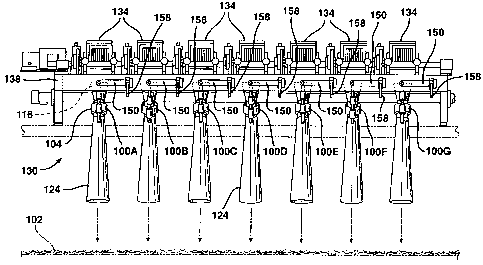
To deposit chopped fibers across a wide moving collection surface, such as
the surface 102, at least one bank 130 of air cannons 100 are mounted across
the surface
102, see Figs. 3 and 4. One or more additional banks 130 of air cannons 100
can be
provided to increase the thickness of the mat of chopped fibers deposited on
the surface
102 with two banks of air cannons 130 being shown in the machine schematically
illustrated in Fig. 9. While a bank can comprise a single air cannon with a
series of banks
stepped or staggered across the surface 102, preferably the bank 130 comprises
a plurality
of air cannons 100 which are mounted in-line across the surface 102 and
positioned
relative to one another to reduce interference therebetween. As illustrated in
Figs. 3 and 4,
seven air cannons 100 are included in the bank 130, of course more or less
than seven air
cannons can be used in a bank depending upon the size of the surface 102 and
the air
cannons.
The moving collection surface 102 is foraminous and air is drawn through
the surface 102 for example by a blower 131, see Fig. 9, to somewhat assist in
deposition
of chopped fibers on the surface 102 and more importantly to carry away air
received from
_g_
CA 02251881 1998-10-16
WO 97/42368 PCT/CA97/00300
the air cannons 100. The surface 102 moves from up-line of the bank 130 to
down-line of
the bank 130 as indicated by an arrow 132, see Figs. 4 and S. For the bank 130
of seven
air cannons 100 illustrated in Figs. 3 and 4, four of the air cannons 100A,
100C, 100E,
1 OOG are aimed up-line and three of the air cannons 1 OOB, 100D, 100F are
aimed down-
s line to reduce interference between the flows of air and chopped fibers from
the air
cannons 100. Fibers F are fed into fiber choppers 134 as shown in Figs. 5 and
9 in a
conventional manner with one fiber chopper 134 being provided for each air
cannon 100,
see Figs. 3 and 4.
Referring now to Figs. 5-7, the up-line and down-line aiming of the air
cannons 100 is accomplished by mounting the air cannons 100 on generally L-
shaped rods
136 made of steel and having generally horizontal legs 136H pivotally mounted
to a
support frame 138 and generally vertical legs 136V with the air cannons 100
secured to
the generally vertical legs 136V. The L-shaped rods 136 have alternating acute
and obtuse
angles between their horizontal and vertical legs to direct alternate ones of
the air cannons
100 up-line and down-line. As shown in Fig. 6, an L-shaped rod 136U includes
an acute
angle 140 between its horizontal and vertical legs 136H, 136V such that the
air cannon
100 mounted thereto is directed up-line, see Figs. 3-5. Fig. 7 illustrates an
L-shaped rod
136D which includes an obtuse angle 142 between its horizontal and vertical
legs 136H,
136V such that the air cannon 100 mounted thereto is directed down-line, see
Figs. 3-5.
The separation of the inlet cone 116 from the air amplifier 104 is clearly
illustrated in Figs. 6 and 7 wherein the inlet cones 116 of the air cannons
100 are
supported directly from the generally vertical legs 136V of the L-shaped rods
136 by
brackets 144 extending between the legs 136V and the inlet cones 116. The air
amplifier
104 and outlet cone 124, which is secured to the air amplifier 104, are
similarly supported
from the generally vertical legs 136V of the L-shaped rods 136 by brackets
146. The inlet
ends 120 of the inlet cones 116 of the air cannons 100 can be formed at right
angles
relative to the respective axes A of symmetry of the inlet cones 116 or can be
angularly
oriented relative to the axes A, for example to make the inlet ends 120
generally
horizontally oriented. Further, the inlet ends 120 can be beveled or rolled
outwardly. It is
currently preferred to make the inlet ends 120 for the air cannons 100 square
to the axes A
of symmetry of the inlet cones 116 and rolled outwardly.
-9-
CA 02251881 1998-10-16
WO 97/42368 PCT/CA97/00300
In addition to the up-line and down-line alternation of the air cannons 100,
each of the air cannons 100 can be moved in the cross direction or from side-
to-side as
shown in Figs. 3 and 4. This side-to-side or cross-mat movement of the air
cannons 100 is
performed by rotating the generally horizontal legs 136H in bearings 148 which
provide
the pivotal mounting of the generally L-shaped rods 136 to the support frame
138. To this
end, a first end of an adjustment arm 150 is secured and preferably keyed to
the ends of
each of the generally horizontal legs 136H, see Fig. 8. A second end of each
adjustment
arm 150 terminates in an adjustment plate 152 which includes an oblong slot
154 formed
therein.
An eye bolt 156 having an eye 156A on one end and threads 156B on the
other end is passed through the slot 154 and threaded into a threaded bore
appropriately
located on the support frame 138, see Fig. 6. A cam lever 158, see Figs. 3, 5,
6 and 7, is
mounted for pivotal movement to the eye 156A of the eye bolt 156. When the cam
lever
158 is raised, the adjustment arm 150 can be moved upward or downward about an
axis
159 with its movement being limited by the ends of the slot 154 engaging the
eye bolt 156.
For upward movement of the adjustment arm 150, the generally vertical leg 136V
moves
to the right as indicated by arrows 160, and for downward movement of the
adjustment
arm 150, the generally vertical leg 136V moves to the left as indicated by
arrows 162, see
Fig. 8. Once the adjustment arm 150 is positioned such that the air cannon 100
is aimed as
desired, the cam lever 158 is lowered to lock the adjustment arm 150 to the
support frame
138. As should be apparent, the generally vertical legs 136V and hence the air
cannons
100 can thus be adjusted back and forth relative to the surface 102 in a
generally arcuate
motion as indicated by double-headed arrow 164, see Fig. 8.
Reference will now be made to Fig. 9 which schematically illustrates a
machine 166 for making chopped strand mat in accordance with the present
invention. A
station 168 includes two banks 130 of air cannons 100 represented by the fiber
choppers
134 which receive and chop fibers F and pass chopped fibers to the air cannons
100 as
described above. The air cannons 100 are not shown but are positioned within
the forming
hood 170 of the station 168.
A mat 172 of chopped fibers as deposited on the moving collection surface
102 is passed to a binder depositor 174 wherein a binder is applied to the mat
172 of
chopped fibers. For example, for a powder mat, the binder may be powdered
unsaturated
-10-
CA 02251881 2004-07-27
polyester having a glass transition point from approximately 95°F to
160°F (35° to 71°C),
preferably between about 105°F to 120°F (41 ° to
49°C), which is applied to the mat 172; and,
for an emulsion mat, the binder may be a liquid polyvinyl acetate emulsion
which is sprayed
onto the mat 172.
The resulting binder treated mat 176 is passed through apparatus for applying
energy, for example heat applied by ovens 178, 180 as illustrated in Fig. 9,
to activate the
binder, i.e., to liquify a powder thermoplastic binder, to drive off the water
from an aqueous
binder or to effect curing of a thermosetting binder. It is noted that for
production of a mat
using an aqueous binder, the application of energy, such as heat, may not be
required since the
mat may be air dried; however, for faster drying it is preferred. The
resulting chopped strand
mat 182 is then passed through compacting/cooling rollers 184, after which it
is further cooled
by a cooling fan 186.
The chopped strand mat may then be passed through slitters 188 which cut the
chopped strand mat to desired widths, feed rollers 190 and a cutter 192 which
cuts the
continuous mat into appropriate package lengths. Finally, the chopped strand
mat is rolled up to
form a roll package 194. Those desiring additional details regarding the
production of chopped
strand mat and the like, which are well known by those skilled in the art, can
be determined by
reference to The Manufacturing Technology of Continuous Glass Fibres, Second
edition, by
K.L. Loewenstein, published by Elsevier in 1983. It is noted that any type of
appropriate
process may be employed down-line of the station 168 to form chopped strand
mat from the
mat 172 which is produced by the station 168.
Having thus described the invention of the present application in detail and
by
reference to preferred embodiments thereof, it will be apparent that
modifications and
variations are possible without departing from the scope of the invention
defined in the
appended claims.
-11-