Sélection de la langue

Search

Sommaire du brevet 2252615 

Énoncé de désistement de responsabilité concernant l'information provenant de tiers

Une partie des informations de ce site Web a été fournie par des sources externes. Le gouvernement du Canada n'assume aucune responsabilité concernant la précision, l'actualité ou la fiabilité des informations fournies par les sources externes. Les utilisateurs qui désirent employer cette information devraient consulter directement la source des informations. Le contenu fourni par les sources externes n'est pas assujetti aux exigences sur les langues officielles, la protection des renseignements personnels et l'accessibilité.

Disponibilité de l'Abrégé et des Revendications

L'apparition de différences dans le texte et l'image des Revendications et de l'Abrégé dépend du moment auquel le document est publié. Les textes des Revendications et de l'Abrégé sont affichés :

  • lorsque la demande peut être examinée par le public;
  • lorsque le brevet est émis (délivrance).
(12) Brevet: (11) CA 2252615
(54) Titre français: PROCEDE DE PRODUCTION D'UNE LAMPE A INCANDESCENCE ELECTRIQUE
(54) Titre anglais: METHOD FOR MANUFACTURING AN ELECTRIC LIGHT BULB
Statut: Périmé et au-delà du délai pour l’annulation
Données bibliographiques
(51) Classification internationale des brevets (CIB):
  • H01K 03/06 (2006.01)
  • H01K 01/18 (2006.01)
  • H01K 09/08 (2006.01)
(72) Inventeurs :
  • RITTNER, ROLAND (Allemagne)
(73) Titulaires :
  • PATENT-TREUHAND-GESELLSCHAFT FUER ELEKTRISCHE GLUEHLAMPEN MBH
(71) Demandeurs :
  • PATENT-TREUHAND-GESELLSCHAFT FUER ELEKTRISCHE GLUEHLAMPEN MBH (Allemagne)
(74) Agent: SMART & BIGGAR LP
(74) Co-agent:
(45) Délivré: 2006-08-15
(86) Date de dépôt PCT: 1998-02-10
(87) Mise à la disponibilité du public: 1998-09-03
Requête d'examen: 2002-09-20
Licence disponible: S.O.
Cédé au domaine public: S.O.
(25) Langue des documents déposés: Anglais

Traité de coopération en matière de brevets (PCT): Oui
(86) Numéro de la demande PCT: PCT/DE1998/000367
(87) Numéro de publication internationale PCT: DE1998000367
(85) Entrée nationale: 1998-10-20

(30) Données de priorité de la demande:
Numéro de la demande Pays / territoire Date
197 07 245.3 (Allemagne) 1997-02-25

Abrégés

Abrégé français

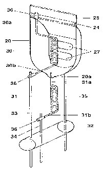
L'invention concerne un procédé de production d'une lampe à incandescence électrique qui comprend au moins un filament boudiné (31) et un capuchon anti-éblousissant (20). Au cours dudit procédé présenté, une extrémité (31a) d'un filament boudiné (31) est enfilée dans une entaille (23) ménagée dans le bord du capuchon anti-éblouissant (20) et fondu avec le dit capuchon anti-éblouissant (20). A cette effet, on fait fondre le matériau du capuchon anti-éblouissant (20) dans la zone de l'entaille (23) de sorte que la matière en fusion mouille l'extrémité (31a) du filament boudiné placé dans l'entaille (23) et que cette extrémité (31a) du filament boudiné soit incorporée dans la matière (20a) du capuchon anti-éblouissant (20) après solidification de celle-ci.


Abrégé anglais


The invention relates to a method for manufacturing an electric light bulb
containing at least one spiral-wound filament (31) and a dimmer cap (20).
According
to the invention, one end (31a) of a spiral-wound filament (31) is threaded in
a notch
(23) on the rim of the dimmer cap (20) and melted on to the dimmer cap (20).
This
is done by melting the material of the dimmer cap (20) in the area of the
notch (23)
so that the molten elements wet the spiral-wound filament (31a) arranged in
the
notch (23) and the spiral-wound filament (31) is embedded in the solidified
material
(20a) of the dimmer cap (20)after the molten elements have hardened.

Revendications

Note : Les revendications sont présentées dans la langue officielle dans laquelle elles ont été soumises.


-6-
Claims
1. Method for producing an electric incandescent
lamp, which has a lamp vessel (1), at least one
incandescent filament (31) and an anti-dazzle device
(20), characterized in that the method contains the
following steps:
- Provision of an anti-dazzle device (20) whose edge
is provided with a notch (23),
- Provision of an incandescent filament (31),
- Threading an incandescent filament end (31a) into
the notch (23), and
- Melting the anti-dazzle device (20) with the
incandescent filament end (31a) arranged in the
notch (23) by melting the material of the anti-
dazzle device (20) in the region of the notch (23)
so that the melt wets the incandescent filament
end (31a) arranged in the notch (23), and the
incandescent filament end (31a) is embedded after
the melt solidifies in the solidified material
(20a) of the anti-dazzle device (20).
2. Method according to Claim 1, characterized in
that the material of the anti-dazzle device (20) is
melted on both sides of the notch (23).
3. Method according to Claim 1, characterized in
that the anti-dazzle device (20) is produced from a
metal sheet.
4. Method according to Claim 1, characterized in
that the notch (23) on the edge of the anti-dazzle
device (20) is a V-shaped or U-shaped interspace which
is formed by two neighbouring projections (21, 22)
projecting from the anti-dazzle device (20).
5. Method according to Claim 4, characterized in
that to fasten the incandescent filament end (31a)
arranged in the notch (23), the two projections (31,
32) are heated and melted.
6. Electric incandescent lamp having two
incandescent filaments (30, 31) and an anti-dazzle
device (20) for one of these incandescent filaments

-7-
(30) produced in accordance with the method according
to Claim 1.

Description

Note : Les descriptions sont présentées dans la langue officielle dans laquelle elles ont été soumises.


CA 02252615 2005-06-10
v 77332-14
1
Method for manufacturing an electric light bulb
The invention relates to a method for producing an
electric incandescent lamp of the type which has a lamp
vessel, at least one incandescent filament and an anti-
dazzle device.
I. Prior Art
Such a method of production is disclosed, for
example, in German Patent DE 22 43 717. This patent,
describes a two-filament halogen incandescent lamp having an
anti-dazzle device and an incandescent filament arranged in
the anti-dazzle device. The anti-dazzle device has a
welding lug provided with a transverse rib. The
incandescent filament ends are wrapped in each case in a
metal foil. Here, the incandescent filament is fixed on the
anti-dazzle device by fastening one of the filament ends
enclosed in the metal foil to the transverse rib by a spot
weld.
II. Description of the Invention
It is the object of the invention to provide a
method for producing an electric incandescent lamp e<~uipped
with an anti-dazzle device and at least one incandescent
filament, which method permits simpler fastening of t:he
incandescent filament end to the anti-dazzle device.
The method of production according to the
invention for an electric incandescent lamp provided with at
least one incandescent filament and an anti-dazzle device is

CA 02252615 1998-10-20
- 2 -
distinguished in that said method has the following
production steps:
- Provision of an anti-dazzle device whose edge is
provided with a notch,
- Provision of an incandescent filament,
- Threading an incandescent filament end into the
notch, and
- Melting the anti-dazzle device with the
incandescent filament end arranged in the notch by
melting the material of the anti-dazzle device in
the region of the notch so that the melt wets the
incandescent filament end arranged in the notch,
and the incandescent filament end is embedded
after the melt solidifies in the resolidified
material of the anti-dazzle device.
By comparison with the prior art, the method of
production according to the invention renders possible
a simpler fastening of an incandescent filament end to
the anti-dazzle device, because now at least one of the
metal foils enclosing the filament ends can be saved.
Fusing the incandescent filament end in a notch on the
edge of the anti-dazzle device in the way according to
the invention can be carried out both for uncoiled and
for coiled incandescent filament ends. In order to fuse
the anti-dazzle device with the incandescent filament
end threaded in the notch at the edge of the anti-
dazzle device, the material of the anti-dazzle device
is advantageously melted on both sides of the notch. It
is thereby ensured that the incandescent filament end
is embedded completely in the resolidified melt of the
anti-dazzle device. The anti-dazzle device is
advantageously formed from a metal sheet so that it can
serve as an electric supply lead for the incandescent
filament connected to the anti-dazzle device. The notch
at the edge of the anti-dazzle device is advantageously
formed from two neighbouring projections projecting
from the anti-dazzle device, which have a V-shaped or
U-shaped interspace. These two exposed projections can

CA 02252615 1998-10-20
- 3 -
be heated and melted with a comparatively low
expenditure of energy with the aid of a laser. The
method of production according to the invention is
particularly suitable for producing two-filament
halogen incandescent lamps which are used as a light
source in motor vehicle headlamps.
III. Description of the preferred exemplary embodiment
The invention is explained in more detail below with
the aid of a preferred exemplary embodiment. In the
drawing:
Figure 1 shows an incandescent filament frame,
produced in accordance with the method
according to the invention, for a two-
filament halogen incandescent lamp having two
incandescent filaments, an anti-dazzle device
and the supply leads associated therewith,
Figure 2 shows an anti-dazzle device provided for the
method of production according to the
invention, and
Figure 3 shows a two-filament halogen incandescent
lamp in accordance with the prior art.
The method of production according to the invention is
to be explained below with the aid of a two-filament
halogen incandescent lamp, a so-called H4 lamp. The
design of the H4 lamp is represented diagrammatically
in Figure 3. The two-filament halogen incandescent lamp
depicted in Figure 3 has a lamp bulb 1 which is made
from hard glass and is pinched in a sealed fashion at
one end. The pinch seal 10 of the lamp bulb 1 is fixed
in a clamped fashion in a pot-shaped holder part 2 made
from stainless steel. The holder part 2 forms the lamp
cap together with the cap shell 3 and the adjusting
plate 4 integrally formed thereon as well as with the

CA 02252615 1998-10-20
- 4 -
cap insulator 5. The holder part 2 is welded to the
adjusting plate 4 via welding lugs 13 punched out of
the adjusting plate 4 and bent upwards. Located inside
the lamp bulb 1 are two incandescent filaments 6, 7
which are respectively connected in an electrically
conducting fashion to a contact lug 9 via a total of
three supply leads 8 projecting from the pinch seal 10
and sealed between two quartz beams 11. One of the
incandescent filaments 6 is provided with an anti
dazzle device 12.
In order to produce the incandescent filament holder of
an H4 lamp in accordance with the method of production
according to the invention, a prefabricated trough-like
anti-dazzle device 20 is prepared from a metal sheet,
preferably a molybdenum sheet (Figure 2). At its edge,
this anti-dazzle device 20 has two neighbouring
projections 21, 22, which project like teeth and form
with one another an interspace constructed as a V-shape
or U-shaped notch 23. The anti-dazzle device 20 further
has a welding lug 25 provided with a transverse rib 24.
The base of the anti-dazzle device 20 is fitted with
two projections 27. Furthermore, two prefabricated
incandescent filaments 30, 31 and three supply lead
wires 33, 34, 35 made from molybdenum are provided for
the method of production according to the invention. In
order to fix the anti-dazzle device 20, the supply lead
wire 35 is welded on the outside of the anti-dazzle
device 20 to the two projections 27 arranged in the
base 26 of the anti-dazzle device 20.
The ends 30a, 30b of the dipped beam filament 30 are in
each case wrapped in a molybdenum foil 36 and spot
welded to the transverse rib 24 on the welding lug 25
of the anti-dazzle device 20 or to an end of the supply
lead wire 33, with the result that the incandescent
filament 30 is arranged in the anti-dazzle device 20.
In order to fix the main beam filament 31 arranged
below the anti-dazzle device 20, an end 31a of the main

CA 02252615 1998-10-20
- 5 -
beam filament 31 is inserted into the notch 23 formed
- by the tooth-like projections 21, 22, and the two
projections 21, 22 are subsequently heated and melted
simultaneously with the aid in each case of a LASER
beam acting for a short time on the two projections 21,
22, with the result that the filament end 31a is wetted
by the melt and completely enclosed. After the
solidification of the melt, the end 31a of the main
beam filament 31 is completely embedded in the
solidified material 20a of the anti-dazzle device 20.
The resolidified material 20a then forms the shading
nose 20a of the anti-dazzle device 20. The other end
31b of the main beam filament 31 is wrapped in a
molybdenum foil 36 and spot welded to the supply lead
wire 34. The incandescent filament frame produced in
this way is depicted with the anti-dazzle device in
Figure 1. This complete filament frame is inserted in a
known way into the prefabricated lamp bulb 1 and
mounted. Sealing the lamp bulb 1 by means of the pinch
seal 10, and capping the lamp are likewise prior art
and are therefore not to be described in more detail
here.
The invention is not restricted to the exemplary
embodiment explained in detail. For example, the
filament end 30a of the dipped beam filament 30 which
is welded to the transverse rib 24 can also be fused in
the same way as the end 31a of the main beam filament
31 with the edge of the anti-dazzle device 20.
Moreover, the application of the fusing according to
the invention of incandescent filament end and anti-
dazzle device is not restricted to two-filament halogen
incandescent lamps.

Dessin représentatif
Une figure unique qui représente un dessin illustrant l'invention.
États administratifs

2024-08-01 : Dans le cadre de la transition vers les Brevets de nouvelle génération (BNG), la base de données sur les brevets canadiens (BDBC) contient désormais un Historique d'événement plus détaillé, qui reproduit le Journal des événements de notre nouvelle solution interne.

Veuillez noter que les événements débutant par « Inactive : » se réfèrent à des événements qui ne sont plus utilisés dans notre nouvelle solution interne.

Pour une meilleure compréhension de l'état de la demande ou brevet qui figure sur cette page, la rubrique Mise en garde , et les descriptions de Brevet , Historique d'événement , Taxes périodiques et Historique des paiements devraient être consultées.

Historique d'événement

Description Date
Le délai pour l'annulation est expiré 2010-02-10
Lettre envoyée 2009-02-10
Accordé par délivrance 2006-08-15
Inactive : Page couverture publiée 2006-08-14
Inactive : Taxe finale reçue 2006-05-25
Préoctroi 2006-05-25
Un avis d'acceptation est envoyé 2005-11-28
Lettre envoyée 2005-11-28
Un avis d'acceptation est envoyé 2005-11-28
Inactive : Approuvée aux fins d'acceptation (AFA) 2005-10-27
Modification reçue - modification volontaire 2005-06-10
Inactive : Dem. de l'examinateur art.29 Règles 2004-12-15
Inactive : Dem. de l'examinateur par.30(2) Règles 2004-12-15
Lettre envoyée 2002-11-01
Modification reçue - modification volontaire 2002-10-28
Requête d'examen reçue 2002-09-20
Exigences pour une requête d'examen - jugée conforme 2002-09-20
Toutes les exigences pour l'examen - jugée conforme 2002-09-20
Symbole de classement modifié 1999-01-06
Inactive : CIB attribuée 1999-01-06
Inactive : CIB en 1re position 1999-01-06
Inactive : CIB attribuée 1999-01-06
Inactive : Notice - Entrée phase nat. - Pas de RE 1998-12-18
Demande reçue - PCT 1998-12-11
Demande publiée (accessible au public) 1998-09-03

Historique d'abandonnement

Il n'y a pas d'historique d'abandonnement

Taxes périodiques

Le dernier paiement a été reçu le 2006-01-18

Avis : Si le paiement en totalité n'a pas été reçu au plus tard à la date indiquée, une taxe supplémentaire peut être imposée, soit une des taxes suivantes :

  • taxe de rétablissement ;
  • taxe pour paiement en souffrance ; ou
  • taxe additionnelle pour le renversement d'une péremption réputée.

Les taxes sur les brevets sont ajustées au 1er janvier de chaque année. Les montants ci-dessus sont les montants actuels s'ils sont reçus au plus tard le 31 décembre de l'année en cours.
Veuillez vous référer à la page web des taxes sur les brevets de l'OPIC pour voir tous les montants actuels des taxes.

Historique des taxes

Type de taxes Anniversaire Échéance Date payée
Enregistrement d'un document 1998-10-20
Taxe nationale de base - générale 1998-10-20
TM (demande, 2e anniv.) - générale 02 2000-02-10 2000-01-21
TM (demande, 3e anniv.) - générale 03 2001-02-12 2001-01-19
TM (demande, 4e anniv.) - générale 04 2002-02-11 2002-01-21
Requête d'examen - générale 2002-09-20
TM (demande, 5e anniv.) - générale 05 2003-02-10 2003-01-24
TM (demande, 6e anniv.) - générale 06 2004-02-10 2004-01-23
TM (demande, 7e anniv.) - générale 07 2005-02-10 2005-01-19
TM (demande, 8e anniv.) - générale 08 2006-02-10 2006-01-18
Taxe finale - générale 2006-05-25
TM (brevet, 9e anniv.) - générale 2007-02-12 2007-01-16
TM (brevet, 10e anniv.) - générale 2008-02-11 2008-01-11
Titulaires au dossier

Les titulaires actuels et antérieures au dossier sont affichés en ordre alphabétique.

Titulaires actuels au dossier
PATENT-TREUHAND-GESELLSCHAFT FUER ELEKTRISCHE GLUEHLAMPEN MBH
Titulaires antérieures au dossier
ROLAND RITTNER
Les propriétaires antérieurs qui ne figurent pas dans la liste des « Propriétaires au dossier » apparaîtront dans d'autres documents au dossier.
Documents

Pour visionner les fichiers sélectionnés, entrer le code reCAPTCHA :


Pour visualiser une image, cliquer sur un lien dans la colonne description du document. Pour télécharger l'image (les images), cliquer l'une ou plusieurs cases à cocher dans la première colonne et ensuite cliquer sur le bouton "Télécharger sélection en format PDF (archive Zip)" ou le bouton "Télécharger sélection (en un fichier PDF fusionné)".

Liste des documents de brevet publiés et non publiés sur la BDBC .

Si vous avez des difficultés à accéder au contenu, veuillez communiquer avec le Centre de services à la clientèle au 1-866-997-1936, ou envoyer un courriel au Centre de service à la clientèle de l'OPIC.


Description du
Document 
Date
(aaaa-mm-jj) 
Nombre de pages   Taille de l'image (Ko) 
Dessin représentatif 1999-01-27 1 6
Abrégé 1998-10-19 1 14
Revendications 1998-10-19 2 53
Description 1998-10-19 5 235
Dessins 1998-10-19 3 41
Description 2005-06-09 5 230
Dessin représentatif 2006-07-13 1 8
Avis d'entree dans la phase nationale 1998-12-17 1 192
Courtoisie - Certificat d'enregistrement (document(s) connexe(s)) 1998-12-17 1 115
Rappel de taxe de maintien due 1999-10-12 1 111
Rappel - requête d'examen 2002-10-14 1 115
Accusé de réception de la requête d'examen 2002-10-31 1 176
Avis du commissaire - Demande jugée acceptable 2005-11-27 1 161
Avis concernant la taxe de maintien 2009-03-23 1 170
PCT 1998-10-19 10 344
Correspondance 2006-05-24 1 38