Sélection de la langue

Search

Sommaire du brevet 2253172 

Énoncé de désistement de responsabilité concernant l'information provenant de tiers

Une partie des informations de ce site Web a été fournie par des sources externes. Le gouvernement du Canada n'assume aucune responsabilité concernant la précision, l'actualité ou la fiabilité des informations fournies par les sources externes. Les utilisateurs qui désirent employer cette information devraient consulter directement la source des informations. Le contenu fourni par les sources externes n'est pas assujetti aux exigences sur les langues officielles, la protection des renseignements personnels et l'accessibilité.

Disponibilité de l'Abrégé et des Revendications

L'apparition de différences dans le texte et l'image des Revendications et de l'Abrégé dépend du moment auquel le document est publié. Les textes des Revendications et de l'Abrégé sont affichés :

  • lorsque la demande peut être examinée par le public;
  • lorsque le brevet est émis (délivrance).
(12) Demande de brevet: (11) CA 2253172
(54) Titre français: OUTIL DE RACLAGE
(54) Titre anglais: SCRAPING TOOL
Statut: Réputée abandonnée et au-delà du délai pour le rétablissement - en attente de la réponse à l’avis de communication rejetée
Données bibliographiques
(51) Classification internationale des brevets (CIB):
  • A47L 13/08 (2006.01)
  • A47L 9/02 (2006.01)
  • A47L 13/022 (2006.01)
  • B44D 3/16 (2006.01)
(72) Inventeurs :
  • LANGELAAN, MARTIN JOHN (Royaume-Uni)
(73) Titulaires :
  • PMW ENTERPRISES LIMITED
(71) Demandeurs :
  • PMW ENTERPRISES LIMITED (Royaume-Uni)
(74) Agent: SMART & BIGGAR LP
(74) Co-agent:
(45) Délivré:
(22) Date de dépôt: 1998-11-10
(41) Mise à la disponibilité du public: 1999-05-15
Requête d'examen: 2003-10-21
Licence disponible: S.O.
Cédé au domaine public: S.O.
(25) Langue des documents déposés: Anglais

Traité de coopération en matière de brevets (PCT): Non

(30) Données de priorité de la demande:
Numéro de la demande Pays / territoire Date
9724051.9 (Royaume-Uni) 1997-11-15

Abrégés

Abrégé anglais


A handle 2 has an integral connector 7 for connection with a suction hose
and hand-grip ribs 13-16. A head 6 projects below the handle 7 with a
transverse slot-shaped bottom opening, and a blade 22 extends along the
front margin of the opening with a scraping edge projecting below the
opening. An upstanding projection at the junction between the head 6 and
the handle 2 has a front face which slopes forwardly and downwardly to the
blade 22 for applying manual pressure to the scraping head.

Revendications

Note : Les revendications sont présentées dans la langue officielle dans laquelle elles ont été soumises.


CLAIMS
1. A hand-held scraping tool comprising:
- a handle;
- a connector for connection with a suction pipe;
- a head including at least one suction opening in communication with said
connector and which, in use, is moved over a surface to be scraped; and
- a scraping blade mounted on said head.
2. A scraping tool according to Claim 1, in which said handle has
front and rear ends, said head being mounted at said front end of said
handle and said connector being mounted at said rear end of said handle,
and said connector being in communication with said suction opening via an
internal passage within said handle.
3. A scraping tool according to Claim 1, in which said handle has
a bottom region and said head projects below said bottom region with said
at least one opening disposed proximate the lowermost part of said bottom
region.
4. A scraping tool according to Claim 3, in which said at least one
opening comprises a slot-shaped opening which extends transverse to said
handle.
5. A scraping tool according to Claim 3, in which said at least one
opening lies on a plane which is substantially parallel with said bottom

region.
6. A scraping tool according to Claim 4, in which said blade
projects below said slot-shaped opening.
7. A scraping tool according to Claim 6, in which said blade
extends along a margin of said slot-shaped opening.
8. A scraping tool according to Claim 7, in which said slot-shaped
opening is disposed between said blade and said handle.
9. A scraping tool according to Claim 6, in which said blade is
disposed on a plane which is substantially perpendicular to said slot-shaped
opening.
10. A scraping tool according to Claim 1, in which said handle is
formed with an integral hand grip.
11. A scraping tool according to Claim 10, in which said hand grip
comprises a plurality of transverse ribs formed on a bottom region of said
handle.
12. A scraping tool according to Claim 11, in which there are at
least three such ribs
13. A scraping tool according to Claim 1, in which there is an
upstanding projection located proximate the junction between said head and

said handle.
14. A scraping tool according to Claim 13, in which said
upstanding projection has a front face which slopes smoothly downwards in
a forward direction to said blade.
15. A scraping tool according to Claim 1, in which said head is
integrally formed with said handle.
16. A scraping tool according to Claim 1, in which said connector
is integrally formed with said handle.
17. A scraping tool according to Claim 1, in which said head and
said handle are cast from a self-setting polymeric material.
18. A scraping tool according to Claim 1, in which said blade is
releasably secured to said head.
19. A scraping tool according to Claim 18, in which said blade is
secured by screws received in threaded apertures in said head.
20. A scraping tool according to Claim 1, in which said connector
is upwardly inclined away from said handle.
21. A scraping tool according to Claim 1, in which said connector
is male.

11
22. A scraping tool according to Claim 1, in which said blade
extends transverse to said handle.
23. A hand-held scraping tool comprising:
- an elongate handle having a bottom region and front and rear ends, said
handle containing an internal passage;
- a connector at said rear end of said handle for connecting said passage
with a suction pipe;
- a head formed at said front end of said handle, said head projecting below
said bottom region and including a slot-shaped opening which, in use, is
moved over a surface to be scraped, said opening extending transverse to
said handle on a plane which is substantially parallel to said bottom region,
and said opening being in communication with said passage via said head;
- a hard metal blade mounted on said head to extend along an edge of said
opening which is remote from said handle, said blade being disposed on a
plane which is generally normal to said plane of said opening and having a
sharp scraping edge which extends below said opening.

Description

Note : Les descriptions sont présentées dans la langue officielle dans laquelle elles ont été soumises.

CA 022~3172 1998-11-10
'' '
P827.US
SCRAPING TOOL
TECHNICAL FIELD OF THE INVENTION
This invention relates to hand tools, and more particularly, a hand-held
scraping tool.
BACKGROUND
By way of exampie, boat hulls are protected with toxic anti-fouling paint to
reduce the buildup of marine organisms. In order to ensure continued
protection it is necessary periodically to remove the paint and any adhering
matter and apply a fresh layer. The removal of such material is generally
achieved using a hand-held scraping tool.
Scraping tools are also used in a range of other applications where a layer
of material is to be removed, often being unpleasant or toxic in nature.
The present invention seeks to provide a new and inventive form of scraping
tool.

CA 022~3172 1998-11-10
P827.US
SUMMARY OF THE INVENTION
The present invention proposes a hand-held scraping tool comprising:
- an elongate handle;
- a connector for connection with a suction pipe;
- a head including at least one suction opening in communication with said
connector and which, in use, is moved over a surface to be scraped; and
- a blade mounted on said head and having a scraping edge which extends
transverse to said handle.
More particularly, the invention provides a hand-held scraping tool
comprising:
- an elongate handle having a bottom region and front and rear ends, said
handle containing an internal passage;
- a connector at said rear end of said handle for connecting said passage
with a suction pipe;
- a head formed at said front end of said handle, said head projecting below
said bottom region and including a slot-shaped opening which, in use, is
moved over a surface to be scraped, said opening extending transverse to
said handle on a plane which is substantially parallel to said bottom region,
and said opening being in communication with said passage via said head;
- a hard metal blade mounted on said head to extend along an edge of said
opening which is remote from said handle, said blade being disposed on a
plane which is generally normal to said plane of said opening and having a
sharp scraping edge which extends below said opening.
The tool is used for scraping a surface by pulling the blade over the surface

CA 022~3172 1998-11-10
P827.US
in a rearward direction, which allows considerable manual force to be
applied to the surface being scraped. By connecting the handle to a
vacuum source, e.g. via a flexible hose, material freed from the surface is
removed from the immediate area of the scraping blade, which results in a
more efficient and clean scraping operation.
BRIEF DESCRIPTION OF THE DRAWINGS
The following description and the accompanying drawings referred to
therein are included by way of non-limiting example in order to illustrate how
the invention may be put into practice. In the drawings:
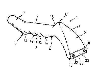
Figure 1 is a general view of a scraping tool in accordance
with the invention;
Figure 2 is a longitudinal section through the tool;
Fi~ure 3 is a bottom view of the front portion of the tool;
Fi~ure 4 is front elevation of the tool;
Fi~ure 5 is a detailed section through the front end of the tool;
and
Fi~ure 6 is a general view of the tool, in use..

CA 022~3172 1998-11-10
';
P827.US
DETAILED DESCRIPTION OF THE DRAWINGS
Referring to Fig.s 1 and 2, the scraping tool includes a main component 1
which is integrally cast or moulded of a strong but lightweight material such
as a plastics or alloy. The component 1 includes an elongate tubular and
generally cylindrical handle 2 having a bottom region 3 and front and rear
ends 4 and 5 respectively, a head 6 being formed at the front end of the
handle 2 and a connector 7 being formed at the rear end of the handle. As
can be seen in Fig. 2, the component 1 is hollow and contains an internal
cavity 8 forming a passage which extends continuously through the head 6,
the handle 2 and the connector 7.
The connector 7 shown in the drawings is male, being generally cylindrical
and open at its rear end 10 with an upward inclination away from the handle
2. The external surface 11 of the connector 7 is slightly tapered for wedging
connection with the female end of a vacuum pipe or hose (not shown). It will
be appreciated however that other forms of connector could be used. For
example, the connector could be female with a tapered internal surface, or
the connector could have an internal or external screw thread for connection
with the vacuum hose. The illustrated connector could also be coupled with
other kinds of vacuum hose fitting via a suitable adaptor. For example, a
short cylindrical sleeve can be used to connect the tool with a male vacuum
hose fitting.
It will be noted that the lower surface of the connector 7 extends downwardly
to form a smooth transversely extending rib 13. In addition, the bottom
region 3 of the handle 2 is formed with three further transversely extending

CA 022~3172 1998-11-10
;
P827.US
ribs 14, 15 and 16 which are smoothly curved to fit comfortably between the
fingers and provide an enhanced grip when the handle 2 is held in the hand.
In addition, the upper region of the handle 2 has an upstanding projection
17, located proximate the junction between the handle 2 and the head 6,
forwardly of the foremost rib 16. The surface of the projection 17 is
smoothly curved, its rear surface18 being generally upwardly inclined in a
forward direction.
The front end 4 of the handle 3 leads smoothly into the head 6 which curves
downwardly to project below the bottom wall 3 and at the same time
progressively becomes narrower in a front-rear direction whilst opening out
transversely to terminate in a rectangular slot-shaped opening 20, best seen
in Fig. 3. The opening 20 extends transverse to the handle and, as seen in
Fig. 2, the opening lies on a plane which is generally parallel to the bottom
region 3 of the handle 2. It will further be noted in Fig. 2 that the opening 20is in communication with the internal cavity 8 via the head 6.
As can be seen in Fig. 4, the front surface 21 of the head 6 has a generally
triangular shape and is contiguous with the front surface of the projection
17, sloping smoothly forwardly and downwardly towards the opening 20
(Fig.s 1 and 2).
Referring to Fig.s 3, 4 and 5, a hard metal blade 22 is secured to the
outside of the head 6 to extend along the front longitudinal margin of
opening 20. The blade may be formed of tungsten carbide or high speed
steel for example and is of generally rectangular shape with the opposed
longitudinal edges 23 and 24 of the blade being ground at an angle to the

CA 022~3172 1998-11-10
P827.US
rear surface 25 to form sharp scraping edges 26 and 27. The rear surface
of the blade 22 is seated against a flat and slightly recessed blade-support
area 28 such that the blade is disposed generally perpendicular to the plane
of the opening 20, or at a very steep angle thereto. In addition it can be
seen that the lower scraping edge 27 projects below the plane of the
opening 20 extending generally parallel thereto. The blade 22 is secured
to the head 6 by screws 30 and 31 which pass through non-threaded
apertures 32 in the blade 22 to be received in screw-threaded apertures 34
in the head 6. It will be appreciated that the uppermost scraping edge 26
is protected by shoulder 36 formed at the flank of the recessed area 28.
However, when the lower edge 27 becomes blunt the screws 30 and 31 can
be removed to allow the blade to be rotated and re-secured with the unused
sharp edge lowermost.
Referring now to Fig. 6, when the tool is used for scraping a surface avacuum hose 38 leading from suction apparatus (not shown) is coupled to
the connector 7, e.g. by means of a short length of elastomeric tube 39
which forms a double-female coupler to connect with a male hose fitting.
The hose 38 applies suction to the opening 20 via the internal cavity 8. The
handle 2 is held in one hand with the fingers located between the ribs 13-16
whilst the other hand is placed on the surface 21 to apply rearward pressure
thereto, with the thumb being placed behind the projection 17. The opening
20 is moved over a surface to be scraped pulling the blade 22 over the
surface in a rearward direction, as indicated by the arrow, at the same time
applying pressure to the head via the surface 21.
From the foregoing it will be seen that the design of the tool allows

CA 022~3172 1998-11-10
P827.US
considerable manual force to be applied to the surface being scraped. At
the same time, material freed from the surface is removed from the
immediate area of the blade 22 so that the action of the blade is not
impeded by a buildup of debris and the scraped area is not obscured.
When both of the scraping edges 26 and 27 become blunt the blade 22 canbe replaced by removing the screws 30 and 31.
Whilst the illustrated tool is particularly suitable for removing toxic materialfrom boat hulls it could be used in other applications1 e.g. to remove lead-
containing paint from a surface.
It will be appreciated that the features disclosed herein may be present in
any feasible combination. Whilst the above description lays emphasis on
those areas which, in combination, are believed to be new, protection is
claimed for any inventive combination of the features disclosed herein.
* * * * * * * *

Dessin représentatif
Une figure unique qui représente un dessin illustrant l'invention.
États administratifs

2024-08-01 : Dans le cadre de la transition vers les Brevets de nouvelle génération (BNG), la base de données sur les brevets canadiens (BDBC) contient désormais un Historique d'événement plus détaillé, qui reproduit le Journal des événements de notre nouvelle solution interne.

Veuillez noter que les événements débutant par « Inactive : » se réfèrent à des événements qui ne sont plus utilisés dans notre nouvelle solution interne.

Pour une meilleure compréhension de l'état de la demande ou brevet qui figure sur cette page, la rubrique Mise en garde , et les descriptions de Brevet , Historique d'événement , Taxes périodiques et Historique des paiements devraient être consultées.

Historique d'événement

Description Date
Inactive : CIB de MCD 2006-03-12
Demande non rétablie avant l'échéance 2005-11-10
Le délai pour l'annulation est expiré 2005-11-10
Réputée abandonnée - omission de répondre à un avis sur les taxes pour le maintien en état 2004-11-10
Lettre envoyée 2003-11-18
Toutes les exigences pour l'examen - jugée conforme 2003-10-21
Exigences pour une requête d'examen - jugée conforme 2003-10-21
Requête d'examen reçue 2003-10-21
Lettre envoyée 2002-03-15
Inactive : Correspondance - Transfert 2002-03-06
Inactive : Lettre officielle 2002-02-20
Inactive : Transfert individuel 2002-01-03
Inactive : Page couverture publiée 1999-05-27
Demande publiée (accessible au public) 1999-05-15
Inactive : CIB attribuée 1999-01-11
Inactive : CIB en 1re position 1999-01-11
Symbole de classement modifié 1999-01-11
Inactive : CIB attribuée 1999-01-11
Inactive : Certificat de dépôt - Sans RE (Anglais) 1998-12-18
Exigences de dépôt - jugé conforme 1998-12-18
Demande reçue - nationale ordinaire 1998-12-18

Historique d'abandonnement

Date d'abandonnement Raison Date de rétablissement
2004-11-10

Taxes périodiques

Le dernier paiement a été reçu le 2003-10-21

Avis : Si le paiement en totalité n'a pas été reçu au plus tard à la date indiquée, une taxe supplémentaire peut être imposée, soit une des taxes suivantes :

  • taxe de rétablissement ;
  • taxe pour paiement en souffrance ; ou
  • taxe additionnelle pour le renversement d'une péremption réputée.

Veuillez vous référer à la page web des taxes sur les brevets de l'OPIC pour voir tous les montants actuels des taxes.

Historique des taxes

Type de taxes Anniversaire Échéance Date payée
Taxe pour le dépôt - petite 1998-11-10
Enregistrement d'un document 1998-11-10
TM (demande, 2e anniv.) - petite 02 2000-11-10 2000-10-30
TM (demande, 3e anniv.) - petite 03 2001-11-13 2001-11-05
Enregistrement d'un document 2002-01-03
TM (demande, 4e anniv.) - petite 04 2002-11-12 2002-11-06
Requête d'examen - générale 2003-10-21
TM (demande, 5e anniv.) - petite 05 2003-11-10 2003-10-21
Titulaires au dossier

Les titulaires actuels et antérieures au dossier sont affichés en ordre alphabétique.

Titulaires actuels au dossier
PMW ENTERPRISES LIMITED
Titulaires antérieures au dossier
MARTIN JOHN LANGELAAN
Les propriétaires antérieurs qui ne figurent pas dans la liste des « Propriétaires au dossier » apparaîtront dans d'autres documents au dossier.
Documents

Pour visionner les fichiers sélectionnés, entrer le code reCAPTCHA :


Pour visualiser une image, cliquer sur un lien dans la colonne description du document. Pour télécharger l'image (les images), cliquer l'une ou plusieurs cases à cocher dans la première colonne et ensuite cliquer sur le bouton "Télécharger sélection en format PDF (archive Zip)" ou le bouton "Télécharger sélection (en un fichier PDF fusionné)".

Liste des documents de brevet publiés et non publiés sur la BDBC .

Si vous avez des difficultés à accéder au contenu, veuillez communiquer avec le Centre de services à la clientèle au 1-866-997-1936, ou envoyer un courriel au Centre de service à la clientèle de l'OPIC.


Description du
Document 
Date
(aaaa-mm-jj) 
Nombre de pages   Taille de l'image (Ko) 
Dessin représentatif 1999-05-27 1 6
Page couverture 1999-05-27 1 27
Abrégé 1998-11-10 1 15
Description 1998-11-10 7 228
Revendications 1998-11-10 4 107
Dessins 1998-11-10 3 40
Courtoisie - Certificat d'enregistrement (document(s) connexe(s)) 1998-12-18 1 114
Certificat de dépôt (anglais) 1998-12-18 1 163
Rappel de taxe de maintien due 2000-07-11 1 109
Courtoisie - Certificat d'enregistrement (document(s) connexe(s)) 2002-03-15 1 113
Rappel - requête d'examen 2003-07-14 1 112
Accusé de réception de la requête d'examen 2003-11-18 1 173
Courtoisie - Lettre d'abandon (taxe de maintien en état) 2005-01-05 1 175
Correspondance 2002-02-20 1 10
Taxes 2003-10-21 1 30
Taxes 2001-11-05 1 30
Taxes 2002-11-06 1 31
Taxes 2000-10-30 1 34