Note : Les descriptions sont présentées dans la langue officielle dans laquelle elles ont été soumises.
CA 02253335 1998-10-28
WO 97/45043 PCT/US97/09080
ENHANCED STORAGE SYSTEM FOR ELE(~RTCAL APPLlANCES, POWERCORDS AND
ADAPI'ERS
~ This application is a continl~tion-in-part of parent applic~tion Serial No. 08/325,039
filed October 18, 1994. This continll~tiQn-in-part applic~tion claims benefits of earlier filing
date of said parent applicAtiQn is by the same inventor as the parent applis~tion and was filed
prior to p~ ;np ~b~n~lonmP.~lt or te~ l;on of procee~ g~ of said parent app~ tion~ in
5 acco,.iance with 35 U.S.C. 120.
TECE~NICAL FIELD
This invention relates to electrical power tools, and in particular to a revised system of
storage app~ s for receiving, h~n~ling and storing small electrical and electronic appli~nces,
10 inc~hldi~ their powecords and adapters.
BACKGROUND OF TE~E INVENTION
Millions of small electrical appli~ncPs are in use in industrialized society, not only in
industry, but in offices, schools, and hot-5ehol~c as well. There is proliferation of hair dlyers,
15 razors, hair clippel~, curling irons, nail polishers, electric toothbrushes, irons, drills, glue guns,
Spl~ , mixers, electric knifes, slicers, and the like. Each appliance requires its own loose
powel~ior,.l. There is also proliferation of a new genelalion of very small electronic appli~nres
such as c~ccette players, CD-ROM drives, cellular tPleph~nes, desktop and laptop colnr~tPrs,
cornrut~r garnes, game controls, recharging devices, converters, adapters, and interface
2 0 mo~ Pc, each requiring a powe~ cord. Many very small appti~nces require a converter, adapter,
.
CA 02253335 1998-10-28
WO 97/45043 PCT/US97/09080
or recl~ger which is most often affixed not to the appliance but to the powercord, to çli~ e
bulk from the appliance. Portable computers comprise separate portable mod~ c disc drives,
modems, and interface terminals, which require cords and adapters of various configllrations.
Often within a ho--cçhol(l each person has his and her own personal asso-LI"c.lL of
5 electric and electronic appliances, inC~ n~ personal hair dryer, razor, electric toothbrush,
c~lc~ tor, c~Ccette player, CD drive, game cartridges, garne controls, and he~dcetc Young
persons especi~lly are more and more equipped with many small appli~ncec electronic toys,
games, game consoles, garne controls, music devices, and gadgets requiring powercords,
adapters, converters, and recharging devices. This results in houcçhold drawers and boxes of
10 appli~ncçc~ electronic devices, powe.~;olds, and adapters.
Each appliance re~luires its own loose powercord. None has been found to tlisc1ose a
storage system comprising interfaced, det~ch~ble storage tool with storage bin shelf for
retention and storage of appli~ncec~ cords, and storage modules in an orderly manner.
As the pace of life accelerates, there is inc.t;as;ng nececc;ly to minirni~e the clutter of
15 small apFl:~nces with loose cords and adapters. Yet, prior to this application, nothing had been
disclosed to solve the problem. Drawers of powercords, adapters, and appli~nces contin~le to
grow. An executive in one col--p~.~y that m~nllf~ctllres small appli~n~çs has co.~ led that
one problem in the industry is the nig~ e of what to do with the maze of assorted
powercords. A need exists for system, appa~aLL~s~ and methods for effi~;ent h~nrlling of small
20 appli~nce$, powercords and adapters, and especially for storing loose puwelcor~s.
SUMMARY OF TE~E INVENTION
In acco.dallce with one aspect of the present invention, a storage system comprising an
interfaced-det~c.h~ble storage tool device, storage bin cont~inçr~ and rack is provided to reel-in
CA 022~333~ 1998-10-28
WO 97/45043 PCT/US97/09080
and store the cord of an electrical appliance, and to hold and store the appliance and adapter, all
efficiently stored in and on the storage bin rack. The cord storage modl~le, with cord stored
thereon, fits and m~tçhes the appliance for which it is selecte~, without motlific~tion or physical
change to the appliance. The module may be interfaced with and re-att~ched to its appliance by
5 quick-acting hook-and-loop straps, thus keeping each cord çffir;~ntly with its appliance.
In another aspect of the present invention, the interfaced, hand-held storage tool with
powercord wound thereon, is capable of effic;ent storage within a storage bin and ~tt~chment to
a rack, by rails located on one flange of the storage tool. The rail, or equivalent ~tt~chm~nt
means, interfaces with a rack such as a series of m~tching slots, or equivalent ~tt~chmPnt
10 hardware, on the rack.
In accordance with another aspect of this invention, the storage tool with powercord
wound thereon may be interfaced and att~hed to its lespecli~e appliance as a unit, with said
unit being capable of efficient storage in, and attachm~nt to, a special storage bin rack.
In accordance with another aspect of this invention, this interface-att~ched and
15 d~t~h~hle, hand-held storage tool with powercord wound thereon, may be attached alternately,
either to the appliance, or to the storage rack for good order and ease of access.
In accordance with an ad-litiQn~l aspect, the powercord storage tool comprises a
ret~ining member flange which may be attached directly to the outside of the storage bin
cQ~ r without 1~4uiling rail brackets. The interface pad, the hook-and-loop straps, and the
2 0 rails or "rail-brackets," are el;~ a~ed from the tool, Pn~hling the rotaling Illclll~er, or r~ h~g
~ll~lllber, of the tool to fit directly into the slot, or interface rack, on the front of the storage bin
cont~in~r. The interface rack has been shaped to receive the ret~ining member; and the front
edge of the container is shaped to accommo~te the rotating knob of the tool, pelll iUillg the
knob to extend over the edge and into the storage co-"ail-er, as the tool is ~tt~ched directly onto
CA 022~333~ 1998-10-28
WO 97/45043 PCT/US97109080
the outside. The retAinii-g I..e.,lber slips directly into the interface rack on the front of the
container. This simplifies construction of the tool and the interface rack.
In accordance with an additional embodiment of this invention, the finger grips on the
powercord storage tool have ben er~onomic~lly desi~ned and shaped to fit and be held by the
5 fingers of one hand of an operator, and to provide openillgs between the fingers holding the
tool, that the fingers may Pfficiently accommodate and control flow of the powercord as it is
being wound onto the spool or ret~ining memher, providing direct sensory feedbaç~ to the
operator of the tension on the powercord while it is being wound onto the storage tooL In this
embodim~nt there are four fingers grips mo~lnted on the base, each concavely curved to
0 accommodate the natural shape of human fingers. A pair of finger grips are opposingly
mol~nted on two opposing sides of the base. Two opposing edges of the base are each shaped
to contain two concave indentions; each inrl~ntion shaped to match and receive the convex
shape of a human finger, and arranged for the tool to be grasped and held in one hand. A finger
grip is fixedly ~t~rhed at each of said indentions of the base. The base of the powercord
15 storage tool is held by the fingers of one hand while the other hand rotates the knob of the
rotating member, thus adroitly winding the cord onto the storage tool. With the base held by
one hand, the i~cQ,..;l~g cord, as it is being wound onto the spool or ~t~ nil~g ~ ..her, is
snugged lightly between fingers of that hand and are guided into the opening between fingers
and finger grips on the ret~ining member, thus giving the operator control of the tension and
20 direction of flow of the cord, pe.."iLli-~g it to be kept applop~iately tight and snug on the spool
and e~ ;n~ g kinks to arrange it straight and smooth on the spool. This enh~nces ~fficien
ease, and eype(~i~ncy of winding and storing the loose powel.iold.
CA 02253335 1998-10-28
WO 97/45043 PCT/US97/09080
BRIEF DESCRIPTION OF TEIE DRAWINGS
A more complete undG~ ;ng of the Invention can be had by rere,~ g to the following
Detailed Description, taken with the accomranying drawings, wherein:
FIGURE la is an iso.l-eL-ic pe ~ re view of non-rotating storage tool l0 rOl~nillg one
5 embo-limP,nt of the present invention.
FIGURE lb is an isometric ptl ~pe~,~ive view of non-rotatable storage tool 30, without
powercord, with straps for interface ~tt~hmpnt to appliance.
FIGURE lc is an isometric perspective view of tool 30, showing a typical powercord
wrapped on the re~ .her.
FIGURE 2a is a side view of rotatable storage tool 40 forming another embodiment of
the present invention, ~tt~ ble to a storage bin rack.
FIGURE 2b is an isometric perspective view of rotatable storage tool 50, as another
emhotlimPnt of tool 40, but with quick-acting, hook-and-loop straps for interface ~tt~t~hment to
a typical appliance.
FIGURE 2c is likewise an isometric perspective view of tool 50, showing a typical
powe ~iol d wrapped on the r~ lg member.
FIGURE 3 is an isometric perspective view of rotatable tool 50, as it would be
interfaced with an ~tt~rhed to the handle of a typical appliance such as an electric hair dryer.
FIGURE 4 is an isometric perspective view of non-rotatable tool l0, with rail-bracket
20 rails for a storage rack, showing the powercord and converter, of an appliance requiring
conversion from AC to DC power, with the converter end of said cord gripped in an notch in
one of the flanges.
CA 022~333~ 1998-10-28
WO 97/45043 PCT/US97/09080
~ IGURE S is an isometric pe-~pecli~e view of storage bin rack 100 as another aspect of
this invention, shown empty, showing the bin and rack which can hold, store, and interface with
typical appli~nces and with rail-bracket rails of said storage tools.
FIGURE 6 is an isometric perspective view of storage bin rack 100, showing t.,vpical use
5 of the components of the storage system of this invention, with typical appliances in typical
position~ as they would be stored and fitted in and on a storage bin rack.
FIGllRE 7a is a side view of rotatable storage tool 250 forming another embo~im~nt in
which interface pad, rail-bracket, and quick-l~tc.hing straps have been ~ n~te(l~ showing
additional aspects of direct ~tt~hment of the storage tool to the storage bin co..l ~ eu
FIGURE 7b is an isometric perspective view of rotatable storage tool 250, showing
ergonomic finger grips as ad(lition~l embo~im~nts for holding said tool, for guiding the
p~ww~d onto the le~a;n..~ .ll.er~ and for providing direct sensory feedbaçl~ to the operator
of the tension on the powercord as it is being wound onto the storage tool.
FIGURE 7c is an additional isometric pe.~pe.,li~e view of tool 250, showing a typical
,oow~-cord wound onto the ret~ining m~mb~r.
FIGURE 8 is an isometric perspective view of rot~t~hle tool 250, with powerco~l
wound thereon while the powercord is att~çhPd to its typical electrical appliance, with
powercord wound onto ret~ining member or spool, with plus end of cord gripped in one notch
in the flange of the ret~inin~ member, and appliance end gripped in the other notch.
2 o Figure 9 is an isometric perspective view of rotatable tool 250, showing the powercord
and converter of a typical appliance requiring conversion from AC to DC power, with the plug
end of the cord gripped in one notch in the flange and the converter end gripped in the other
notch.
CA 02253335 1998-10-28
WO 97/45043 PCT/US97/09080
FlGURE 10 is an isometric perspective view of storage bin co..l~ner 500 as another
embodiment of this invention, shown empty, which can hold, store, and interface with typical
appliances, adapters, and storage tools, and shown with interface racks or slots on the front
which interface and fit directly with the ret~ining member 214 of powercord storage tool 250,
without the rail brackets that would otherwise be required FIGURE 10 also shows schPm~Atic
Ali~men~ of two powercord storage tools 250, in location and ~lignm~ont above the re~peclive
interface racks, into which they may be inserted, for holding said tools outside said CGI~l Ai~
FIGURE 11 is an isometric perspective view of storage Collt~in~r 500, showing typical
use ofthe enhAnced storage system ofthis invention, with typical appli~nces in typical positions
0 as the powercord will be wound onto the storage tool 250, the appli~ncçs and adapters stored
inside the appliance storage contAiner 500, and the tools, with cord thereon, interfaced and fitted
onto the outside ofthe co~tAiner 500, on the contAin~or interface rack 512, or 514, or 516.
DETAILED DESCRIPTION OF T~E PREFERRED EMBODIMENT
Referring now to the drawings, wherein like reference numerals design~te like orcG--~ ,onding parts throughout the several views; in FIGURE la, there is illustrated a storage
tool 10 forming one embo-linlent ofthe present invention, but empty, i.e., without p~wereord.
FIGURE la is an isolllel.ic pe.~pec~ e view of empty storage tool 10, without
powercord, co,.".lising r~lain ng member 12 with non-rotaling flange 14 located on one end and
non-rotating flange 16 on the other end Flange 14 colllains notches 18 and 20 for securing the
ends of a typical powelcord not shown in FIGURE la, to be wrapped onto relAi~ g .~e~ber
12. Rail-blacl~ts 22 and 24 are shown as fixedly attAched to flange 14 and shaped and arranged
in a manner as shown in FIGURES 5-6 to match and fit within storage slot 112-114 of storage
bin 100
CA 022~333~ 1998-10-28
WO 97/45043 PCT/US97/09080
FIGllRES lb-1c are perspective views of storage tool 30, which is another embodiment
ofthisinvention. InFIGURE 1b,tool30isempty,i.e.,withoutpowwcord,andforillustration
purposes, parts of flanges 14 and 16 have been cut away to show ~ member 12, as in
other drawings herein. Notice that tool 30 is another embodiment oftool 10 of FIGURE la. In
tool 30, contact surface 36a has been selected for interface with a typical appliance; flange 14 is
fitted, at surface 36a, with resilient interface pad 36 which may be col"p,essed to conform to the
shape of handle 74 as shown in FIGURE 3; rail-brackets 22 and 24 are shaped and arranged, as
shown in FIGURE 3, to align with handle 74 of a typical electrical appliance 72; and contact
surface 36a, as fitted with resilient, conformable pad 36, and rail-bracket rails 22 and 24, which
tog~o,ther cooperatively form a concave interface pocket, shaped to COl~"" to a selected portion
such as a handle 74 of a selecte~l typical electrical appliance such as a typical hair dryer 72; and
flexible straps 32 and 34 are fixedly attached to flange 14 and to rail-brackets 22 and 24
respectively, as means for attaçhing tool 30 to handle 74, in a manner as shown in FIGURE 3
wherein they may be wrapped around handle 74 and removably latched.
In the embodiment of FIGURE lb, means for attarhing the tool 30 to handle 74 as
shown in FIGURE 3, is ~ osed as fleYible straps 32 and 34, comprising fl~yihle~ ~uick-acting,
plastic hook-and-loop materials, but may equivalently be comprised of other ~tt3çhin~ means
well known to persons of ordinary skill in the art, such as straps with a buckle, and other
e~uivalent means for atta~hing
FIGURE 1c is an isometric perspective view of tool 30 with a typical powwcord 70stored thereon, being wound between flanges 14 and 16 onto .~t~ it-g member 12, which in this
view is hidden beneath powercord 70. FIGURE 1c illustrates that one end of powercord 70
may be removably gripped in notch 18, and the other end of powercord 70 likewise may be
gripped in notch 20.
.
CA 022~333~ 1998-10-28
WO 97/45043 PCT/US97/09080
FIGURE 2a is an illustration of rotatable storage tool 40 comprising r~t~ g mPmher
12 with flange 14 fixedly att~rhed to one end of ret~inin- member 12, and with flange 42
rotatably ~tt~ched to the other end of retaininp. member 12 by means of pivot pin 44. Knob
handle 46 is ro~lably attachP,d to an outside portion of flange 14 as means for m~m~ y rotating
flange 14 and ret~ining tnemher 12 about pivot pin 44 with respect to flange 42. Rail-bracket
24, and likewise typical rail-bracket 22 which is not visible in this view of FIGURE 2a, are
fixedly att~chP,d to flange 14, as means for fitting tool 40 into m~trhin~ slot 112-114 of a
storage bin 100 as shown in FIGURE 5.
FIGURE 2b shows rotatable storage tool 50 as another embodiment of this invention,
wherein tool 50 is similar to rotatable tool 40 of FIGURE 2a. In tool 50, rail-brackets 22 and
24 are ~ ged, as shown in FIGURE 3, to align with handle 74 of a typical electrical appliance
72; resilient interface pad 36 is fitted and fixedly att~r.h~d to flange 14 at surface 36a between
rail-brackets 22 and 24; is made of resilient material such as plastic sponge; and may be
compressed to col~,l" to the shape of handle 74 as shown in FIGURE 3; and contact surface
36a as fitted with resilient, collroll.,able pad 36 and side rails 22 and 24, together form a
concave interface pocket, shaped to con~ol", to a selected portion such as a handle 74 flexible
straps 32 and 34 are fixedly ~ttar.hP,d to flange 14 and to rail-brackets 22 and 24 respectively, in
a manner as shown in FIG~RE 2b wherein they may be wrapped around handle 74 and
removably l~tc.hed as shown in FIGURE 3.
In FIGURE 2b, means for attaching tool 50 to handle 74 as shown in FIGURE 3, is
disclosed as flexible straps 32 and 34, co~l~p.isillg flPYible, quick-acting, plastic hook-and-loop
materials; but the attaching means may equivalently be comprised of other attaching means well
known to persons of ordinary skill in the art, such as flexible straps with a buckle, clamps,
gripping hardware, and other equivalent means for ~tt~r.hing
CA 022~333~ 1998-10-28
WO 97/45043 PCT/US97/09080
FIGURE 2c of rotatable storage tool 50, shows how a typical powercord 70 may be
stored thereon by winding it onto re~ ing member 12 between flanges 14 and 16, illustrating
that one end of powercord 780 may be removably gripped in notch 18, and the other end
likewise gripped in notch 20.
FIGURE 3 illustrates rot~t~ble storage tool 50 as interfaced and fitted onto typical
handle 74 of a typical appliance 72, by means of rail-brackets 22 and 24 and resilient interface
pad 36 which resiliently CO~llllS to the shape of handle 74 as shown in FIGI~RE 3, and as
removably ~tt~rh~d to handle 74 by ~st~ching means well known in the art such as straps 32 and
34 which are in this embodiment comprised of flexible, quick-acting, plastic hook-and-loop
o materials.
FIGURE 4 is an illustration of storage tool 10 as disclosed in this invention, slluwing
how tool 10 will be used to store a typical powercord 82 for a typical appliance such as
converter 80 by wrapping powercord 82 about ret~ining member 12, which in this view is
hidden beneath powercord 82, wound between flanges 14 and 16, with the converter end 86 of
said powercord 82 gripped in notch 18 and the plug end 84 gripped in notch 20. It will be
al~pa,t;llL as ~:c~-losed in this invention, that other embodimentc such as storage tools 10, 30, 40,
and 50, and other equivalent embodiment~, will likewise be useable for storage of pow~lcolds of
other small electric appli~ncPs and electronic appli~ncec, incl~lding powercords with adapters,
converters, and recharging devices fixedly att~he(l such as converter 80.
FIGURE 4 also shows how a pair of finger grips 88a and 88b may be affixed to theinside face of opposing edges of flange 16, for ease of holding tool 10 in one hand while
powercord 82 is m~ml~lly wound onto re~ member 12 not shown in this view of
FIGURE 4. Equivalently, said finger grips 88a and 88b may be likewise affixed to flange 16 of
-10-
CA 022s333s 1998-10-28
WO 97/4S043 PCT/US97/09080
tool 30, and equivalently, likewise affixed to flange 42 on tool 40, and equivalently tool 50, for
ease of holding in one hand.
FIGURE S illustrates storage bin 100, co..",liscd of back 102, fight side 104, left side
106, bottomlO8,and frontllO,which in turn is fitted with leftT-flangell2, left-center
T-flange 113, right-center T-flange 116, and right T-flange 118, which are each shaped and
arranged as shown in FIGURE 5 to form m~trhing slots 112-114, 114-116, and 116-118,
respectively. The bottom of each slot 112-114, 114-116, and 116-118, is each resl)e~ ely
closed with stops 120, 122, and 124.
In FIGURE 5, tool 10 and tool 140 are shown for purposes of sçhPm~tic illustration as
lo sçhem~tic~lly suspended above and aligned with slots 112-114 and 114-116, respcc~ ely~ into
which they each may be fitted for storage, as shown in FIGURE 6. Notice in the embo~impnt of
tool 140 as shown in FIGURES 5-6, tool 140 is similar to rotatable storage tool 40 of FIGURE
2a.
FIGURE 6 shows an ~d~ition~l view of storage bin 100 as disclosed in this embodiment
holding storage tool 10 fitted into slot 112-114, with powercord 152 of typical small electronic
appliance such as earphone-headset 150 wound onto storage tool 10, and in turn, earphone-
he~,dset 150 is stored within bin 100. Likewise, FIGURE 6 shows storage bin 100 holding
storage tool 140 with powercord 82 wrapped thereon oftypical small electronic appliance such
as converter 80, which in turn is stored within storage bin 100, while rail-brackets are fitted
within slot 114-116.
To assure complete ~ closllre, ~hhou~h in some places redund~nt, it is emphasized that
the rotatable storage tool 50 ~tt~ches to typical handle 74 of typical electric hair dryer 72
without requiring mo~ific~tion of the hair d~er in any manner. Storage tool 50 with typical
powercord 76 wound thereon, interfaces with and is ats~rhed to handle 74 of typical hair dryer
CA 022~333~ 1998-10-28
WO 97/45043 PCT/US97/09080
appliance 72, and ~tt~çhes thereto of its own means. It will be apparenl that rot~t~ble storage
tool 50 as shown in FIGURES 2b, 2c, and 3, is fitted with rail-brackets 22 and 24 which are
arranged to interface and fit within slot 112-114, and equivalently with slots 114-116, and
equivalently with slot 116-118, of storage bin 100 of FIGURE 5. Thus, rot~t~ble storage tool
50 with typical powercord 70 wound thereon, may be stored by fitting it into slots 116-118 in a
manner equivalently shown for tools 10 and 140 in FIGURE 6.
In FIGURE 2b, storage tool 50 comprises re~ il-g member 12, with first flange 14fixedly ~tt~hed to one end of said ret~inine member 12. Second flange 42 is rotatably ~tt~rh~
by means of pivot pin 44, which is not visible in views of FIGURES 2b and 2c, to the other end
of ret~ining member 12. A first notch 18 is located on first flange 14, for gripping an end of
typical powercord 70. A second notch 20 is likewise located in first flange 14 for gfil)ping
another end of typical powercord 70. Notches 18 and 20 may be any equivalent gl;pping,
cleating, or wedging means for securing the cord 70 to ret~ining mçmber 12 to prevent
unwinding. Ret~ining In~mh~r 12 is shaped to receive powercord 70 as said cord 70 is wound
onto the storage tool 50.
Knob handle 46 is rotatably att~c-hed near the perimeter of non-rotatable first flange 14.
Knob 46 is used for m~nu~l~y rotating re~ail-ing mçmhçr 12, with its fixedly-att~ched flange 14,
about pivot pin 44 with respect to rotatable flange 42.
An interface contact surface 36a is located on first flange 14. Contact surface 36a is
fitted with resilient, conformable paid 36 and side rails 22 and 24, which togeth~r form a
concave interface pocket, shaped to col~llll to a s~lected portion such as a handle 70 of a
selecterl typical electrical appliance such as typical hair dryer 72.
A pair of straps 32 and 34 are affixed to first flange 14 in a manner to include two
opposing sides of contact surface 36a. The loose strap ends 32 and 34 are co~figllred and
CA 02253335 1998-10-28
WO 97/45043 PCT/US97/09080
ged to be capable of being selectively wl~pped and latched around a selected portion such
as handle 74 of typical appliance 72 as shown in FIGURE 3. Straps 32 and 34 may be made of
conventional strap material such as fabric, leather, or plastic, and may be fitted with conven-
tional r~lel~e-~ such as snaps, buckles, and equivalent fitting means. In this embo~lim~nt straps
5 32 and 34 are made of plastic, quick-l~trhing multiple hook and cor..l.a~ible multiple loop
material f~ctener means of a type conventionally sold under the Velcro~ trademark which is
capable of quick attachment and release.
Ret~ining n~tll.ber 12, flanges 14 and 16, pivot pin 44, knob 46, and rail-brackets 22 and
24, and likewise r~ ini~g membçr 214, base 242, knob 246, and finger grips 248, may be made
10 of any conventional m~mlf~ctll ing materials of ~dequ~te strength for fabrication or casting, such
as wood, metal, and equivalently plastic. Pad 36 may be made of conventioT~l light-weight
resilient materials such as sponge rubber, plastic, and the like.
In typical embodim~ntc such as FIGURES 1-6 and likewise FIGURES 7-11, the
structural col-l~)ol1ell~i of this invention are made of plastic, and equivalent light-weight, durable
15 n~ltl;als, for ease and economy of m~nllf~ctl~re, and for reliability, structural sl~eng~h~ and light
weight.
Accordingl~, fixed flange 14 and 214 and r~ in~ member 12 may be of plastic cast as
a unit, which may be referred to as the rotor and equivalently the ret~ining member, comprising
said fixed flange 14 and 214 with retaining member fixedly attached thereto, and fo.-.ung a part
2 o of said rotor.
The ~ttaçhm~nt is accomrliched without modific.ation of the appliance in any manner,
and is thus readily fitted to many dirrelelll small appli~nces In this embo~im~nt storage tool 50
would be m~nufactllred to interface with the particular appliance 72, by sek~ a l~refell~,d
portion 74 of that appliance 72 for attachm~nt Contact surface 36a, pad 36, and rail-brackets
-13-
CA 022~333~ 1998-10-28
WO 97/45043 PCT/US97/09080
22 and 24 are shaped and arranged to conform to and fit around the shape of selected interface
portion which in the FIGI~RE 3 embodiment would be handle 74.
In still another aspect of the present invention, storage tool 50 is ~tt~ch~hle to a storage
rack 100. In this embo-lim~nt rail-brackets 22 and 24 are shaped to fit and slip into m~t~hing
s slots 112-114 of storage slot 100. Slots 112-114, 114-116, will receive and retain rail-brackets
22 and 24 in a manner to hold storage tool 50 in a selected stored position, for ready ease of
access and orderly storage. In still another aspect, not illustrated here, it will be obvious that the
r~p~hili~y for ~ttachment of storage tool 50 to storage rack 60 may be ornitted by not providing
rails 22 and 24 on sided-braces 22 and 24. Or as seen in FIGURES 7-11, the c~r~hility for
Al ~ h".~ of storage tool 250 to storage co"~ainer 500 may be achieved, without rail-brackets,
by sh~ping re~ -g member 214 and slot 512 to be directly co...~ ;ble as eYpl~ined below.
In typical usage as shown in FIGURES 2c and 2b, an ope. ~tor will grasp empty storage
tool 50 in one hand, holding it by flange 42. For ease of holding tool S0 in one hand, and
equivalently for holding tool 40, and tool 50, in one hand, flange 42, and equivalently flange 16
of tools 10 and 30, may be fixedly equipped with finger grips 88a and 88b, as shown on flange
16 oftool 10 in FIGURE 4. Press the free end of powercord 70 into first notch 18. Grasp knob
46 with the other hand, and rotate first flange 14, as affixed to let~ . member 12, about pivot
point 44 to wind the free length of cord 70 onto ret~ member 12 betweel- flanges 14 and
44. Press the rem~ining end of cord 70 into notch 20 to prevent unwinding. Place the storage
tool 50 with cord 70 wound thereon into position with contact surface 36a, pad 36, and rail-
brackets 22 and 24 aligned and in contact with selected portion 74 of s~lected appliance 72.
Snugly wrap and tightly latch the loose ends of straps 32 and 34 about s~lected portion 74. In
this manner, the powercord 70 will be stored, and storage tool 50 will be ~tt~ched as an integral
-14-
CA 022s333s 1998-10-28
WO 97/45043 PCT/US97/09080
part of appliance 72. Alternately and selectively, storage tools 10, 30, 40, 50, and 140, may be
stored in storage bin 100, and selectively att~ched on said racks, per FIGURES 5-6.
FIGURES 7-11 shows di~clos~.res of alternate embodim~nt~ and ~ddition~l aspects of
this invention over the basic ~ s~res of FIGURES 1-6.
FIGURE 7a is a side view of rotatable storage tool 250 fo."~ing an additional embodi-
ment, showing an alternate means of interface QttQ~hm~nt of the storage tool to the storage bin
container. In this embo-1imçnt, the interface pad, rail-bracket, and quick-l~tchine straps have
been e1;~ A~e(1, thus pleSe~ g shape of flange 214 of the re~A;--;ne member as a flat, planar
surface, without obstruction, which can thus be fitted directly into interface rack 512, or 514, or
0 516, as shown in FIGURE 10 and FIGURE 11. This embodiment simplifies the construction of
storage tool 250 and f~cilit~tçs h~n~line the storage tool 250 and rotation of the ret~inine
member 214 for winding the pc,~vercold thereon. As shown in FIGURE 10 and FIGURE 11,
the racks, 512, 514, and 516, on the outside of the front of the storage contQin~or 500 are shaped
to fit and directly ~cco1nmQdate the planar flange ofthe rotating ...~,.ber 214 ofthe powercord
storage tool 250. Thus, after the powercord has been wound onto a storage tool 250, the tool
250 may be turned with the ~ i"g mw,.ber 214 parallel to the front of the co ~I Qi~ r 500, with
the lolaLiilg knob 246 in the upward position facing into the co~ r 500. The flange 214 of
~,ta;l~g ~ ,nll~el 214 will slip directly into rack 512, or alternately, rack 514, or 516. FIGURE
7a shows side view of base 242, showing ergonomically designed finger grips 248 ~tt~ched, of
2 o which there are a total of four each finger grips 248 per tool 250.
FIGURE 7b is an isometric pc,~eclive view of rotatable storage tool 250, as another
view of this tool, showing the ~implified planar design of flange 246, and additiQn~l aspects as
the ergonomically d~cigned and shaped finger grips 248 on base 242 provide means for holding
said tool 250 in one hand of an operator, means for guiding said powercord between the fingers
CA 02253335 1998-10-28
WO 97/45043 PCTrUS97/09080
of the operator and onto the ret~ining mPmher 214, and means for providing direct sensory
feedbacl~ to the operator of tension on the powercord, and its position and conditio~, while the
powercord is being wound onto the le~ g member 214.
In this embodiment, the inventor has found and hereby diccloses that efficiPncy of
holding the tool 250, gripping the end of the powercord in the notch 218 on the flange 214, and
turning the knob 248 on the ret~inin~....~..,he~ 214 iS Pnh~n~e~ fi~ it~ting ~ nce of the
powercord çfficier~tly onto the ret~ining member 214. Finger grips are dçcigned and shaped to
fit the functional working surfaces of the fingers, whereby tool 250 can be h~n-lled more
adroitly. Finger grips 248 have been placed on the tool in location, so that the fingers of the one
10 hand holding the tool 250, can be concurrently and simlllt~n~oously used to keep the cord
straight, smooth, and snug.
In this embodiment, the tool is grasped in the fingers of one hand by the er~nf)m:~~lly
desi~ed finger grips 248, direct sensory fee~bac~ of tension on the cord is provided to the
operator while the cord is being wound, permitting the operator to control and direct the flow
15 and ~~ ~n~..l ofthe cord onto the tool. The term ergonsmic as used herein is interpreted as
bioteçhnological, of or pellahfing to that aspect of tec-hnology, and particularly ..~oel~
design, applied to fi~nctioîl and movements of the human body, which is conce",ed with the
appli~1;0n of biological and engil-ee~ illg data, both kinetic and dynamic, to problems relating to
the mutual adj..ctmPnt of man and the m~c.hine.
FIGURE 7c is likewise an isometric perspective view of tool 250, showing a typical
powercord wound onto the le~ g member. FIGI~RE 7c shows base 242, shaped finger grips
248, of which there are four each per tool 250, flange-ret~iniQ~ memh~Pr 214, rotaling knob 264,
nstches 218 and 220, and showing a t,vpical powercord wound onto ret~ining m~mher 214.
CA 022~333~ 1998-10-28
WO 97/45043 PCT/US97/09080
FIGURE 8 is an isometric perspective view of rotatable tool 250, showing base 242,
shaped finger grips 248, of which there are four each per tool 250, flange-ret~ining member 214,
rotating knob 264, notches 218 and 220, and showing the powercord of a typical electronic
appliance such as a headset or earphones with powercord, showing the powercord wound onto
the ret~ining memher 214 or spool, with the appliance of said cord gripped in a notch 218 in
flange 214 and the plug end gripped in the other notch 220.
FIGI~RE 9 is an isometric perspective view of rotatable tool 250, showing base 242,
shaped finger grips 248, of which there are four each per tool 250, flange-re~ p. m~omher 214,
rotating knob 264, notches 218 and 220, and showing the powercord and converter of an
lo appliance requiring conversion from AC to DC power, with the converter end of said cord
gripped in a notch 218 in flange 214 and the plug end gripped in the other notch 220.
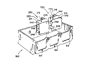
FIGURE 10 in an isGn.et-ic perspective view of storage bin cont~iner S00 as another
embo~iment of this invention, shown empty, showing the container S00 which can hold and
store typical appliances within itself, and showing racks 512, 514, and 516 on the front of said
cont~in~r 500, each of which can interface and fit with the ret~ining member 214 of powercord
storage tool 250, without the rail-brackets that would otherwise be required. FIGURE 10 also
shows sr,hem~tic ~lignm~nt of two powercord storage tools 250, in location and aligned above
the respective interface racks, into which they may be inserted, for holding said tools outside
said containers.
2 o FIGURE 11 is an isometric perspective view of storage cont~in~r 500, showing typical
use of alternate embodiment storage system of this invention, with typical appliances in typical
positions as the powercord will be wound onto storage tool 250, appli~nces and adapters placed
and stored inside the appliance storage container 500, and the tools 250, with cord thereon,
CA 022S333S 1998-10-28
WO 97/45043 PCT/US97/09080
interfaced and fitted onto the outside ofthe cont~in~r 500, on co~ ;n~r interface rack 512, and
alternately rack 514, and S16.
In a~l~hion~l aspects ofthis invention, the storage slots 512, 514, and 516 are so...~;...es
lel~l-ed to as racks; storage bins 500 are so...e~ es referred to as storage bin co.~ 500,
5 and as storage containers 500; and other nom~n~l~tures are likewise used which will be obvious
from the illustrations and are herein intçnded to be equivalent.
While the p-~r~ d embodiment, and typical alternative embodimçntc of the componenl
parts and ~ccçmh!jes of the storage system of this invention have been illustrated in the
aCco...rar.ying drawings and described herein, it is to be understood that the invention is not
10 limited to the embotlimçntc ~licnlosed here, but is equally capable of numerous other equivalent
arrangelll.,..ls, re~li.nge...~..lc ms~1ific~tionc and subsfitlltionc of parts and c~ ..lc
equivalently to achieve the functions, means, ways, and results disclosed herein, without
dc"~ ling from the spirit and te~hin~ of the invention, and are equivalently covered within this
di~closure of this invention.