Note : Les descriptions sont présentées dans la langue officielle dans laquelle elles ont été soumises.
CA 02253359 1998-11-02
1
FLEXIBLE INTRAOCULAR nVIPLANT FORMED IN ONE PIECE
The present invention has for its object a flexible intraocular implant formed
in one piece and, particularly but not exclusively, an implant of this type
intended
to be placed in position in the capsular sac after ablation of the lens.
Intraocular implants may be divided into two large categories depending on
the material with which they are made. So-called flexible intraocular implants
and
so-called rigid intraocular implants are distinguished. The former are made
with
materials of the silicone gel or pHEMA type, the latter generally being made
from
PMMA.
Rigid implants made of PMMA have been developed and manufactured for
numerous years and their shape is perfectly defined. In particular, it is the
case for
the shape of the haptic loops, the function of these loops being to come to
rest on
the periphery of the capsular sac or on the internal wall of the eye in order
elastically to maintain the optical portion of the implant opposite the pupil
of the
1 S patient who has been implanted.
The tendency in eye surgery and, more precisely, in the positioning of
intraocular implants in the eye, is to reduce very substantially the dimension
of the
incision which must be made in the cornea to position the intraocular implant.
It
must be added that, the implant is most often placed in position in the
capsular sac
after ablation of the lens, the techniques of ablation of the lens,
particularly phako-
emulsification, may be carried out by making only an incision of reduced
dimensions, typically of the order of 3 to 4 mm. It was therefore interesting
to have
available intraocular implants capable of being placed in position in the eye
through
such an incision. However, it will be understood that the dimensions of the
optical
portion of the implant, i.e. its diameter, must be sufficient for this optical
portion to
perform its role of correction, even when the pupil is dilated to a maximum
and
despite a slight off centering of the optical portion. It is therefore
necessary that
the optical portion presents a sufficient diameter, typically of the order of
5 to 6
mm.
CA 02253359 1998-11-02
2
Taking all these constraints into account, it will therefore be understood
that only the use of a flexible material allowing the optical portion to be
bent makes
it possible to satisfy the double condition of passing through an incision in
the
cornea of reduced dimensions and of guaranteeing a sufficient diameter of the
optical portion to allow optical correction, whatever the situation.
Consequently, a large number of so-called flexible intraocular implants have
been developed to satisfy these two conditions. However, although the so-
called
flexible materials contribute an interesting solution to the problem of
producing the
optical portion, it is not so concerning the production of the haptic portion.
In fact,
the great flexibility of these materials means that the direct transposition
of the
haptics of the implants made of hard material cannot give satisfaction in the
case of
the flexible materials.
Taking this situation into account, two great types of solution have been
proposed: on the one hand, it has been proposed to make implants in which the
optical portion is flexible and the haptic portion is rigid, typically made of
PMMA.
These techniques are described in particular in Patent Application
PCT/FR95/01344. This solution makes it possible, on the one hand, to benefit
from
pliable, flexible optics and, on the other hand, to use haptic loops made of
PMMA
of which the geometrical definition is perfectly mastered.
It has also been proposed to make the haptic portion for the flexible
implants, not via two loops in C or J form disposed diametrally with respect
to the
optics, but by providing two much more solid haptic portions terminating in
arc-of
circle edges of sufficient length to ensure a sufficient contact between the
periphery
of the capsular sac and the haptic portion. Such flexible implants are
described in
particular in European Patent Application No. 93401744.3.
Nonetheless, it has already been proposed to make flexible implants in one
piece, with a haptic portion constituted by two short loops of relatively
conventional type. However, these implants are unsatisfactory insofar as, due
to
the very great flexibility of this material which presents a modulus of
elasticity
typically less than 0.2 MPa, the haptic loop, under the effect of the stresses
CA 02253359 2002-09-30
resulting from its being positioned in the capsular sac, bends locally in the
region of
the connection of the loop to the periphery of the optical portion. This
results in that
the effective zone of contact between the haptic loops and the periphery of
the
capsular sac is reduced, which does not ensure perfect maintenance in place of
the
optical portion and which risks, especially, causing a deformation of the
capsular sac
with the damaging consequences that this brings about, or even a perforation
of this
capsular sac under the effect of the concentration of" the pressure stresses.
This is
shown in Figure 6, the optical portion being referenced 2, the haptic loops 4
and the
periphery of the capsular sac 6.
The present invention is directed towards the provision of a flexible one-
piece
intraocular implant presenting a haptic portion constituted by loops but which
comprises a haptic portion having improved properties of maintenance and
flexibility
to obtain results substantially equivalent to those which are obtained with
haptic loops
made of PMMA.
In accordance with one aspect of the invention, the intraocular implant which
comprises a substantially circular optical portion and two curved haptic loops
each
with a first connecting end at the periphery of the optical portion and a free
end
intended to come to rest on the internal wall of the eye, is characterized in
that the
optical portion and the haptic loops are made of the same flexible material of
which
the modulus of elasticity is included between 0.25 MPa and 1 MPa, and in that
the
width in the optical plane of each loop decreases from its connecting end to
its free
end such that the varation of the ratio between the variation of the bending
moment
applied to the loop and the inertia moment variation is substantially constant
between
two separate points of the loop over the whole length th.e loop.
Thanks to this specific definition of the geometry of the loop, a distributed
bending of the loop is obtained which thus enables it to adapt itself by
bending to the
different internal diameters of the capsular sac, avoiding a localized bending
of the
loop at the level of its connection to the optical portion and thus producing
a
considerable length of contact between the loop and the internal wall of the
capsular
sac or of the eye depending on the modes of implantation.
CA 02253359 1998-11-02
4
According to a preferred embodiment, each haptic loop further comprises a
complementary arm separate from the loop proper and of which a first end is
connected to the periphery of the optical portion near the connecting end of
the
loop and of which the other end is connected to the loop near its free end,
the
section of said additional arm being smaller than that of the loop, said arm
being
disposed on the concave side of the loop.
Thanks to the presence of a complementary arm associated with each
haptic loop proper, not only the bending properties of the loops according to
the
definition given hereinabove are conserved, but, in addition, the inertia
moment of
each haptic loop is increased with respect to the risks of torsion of the loop
with
respect to its neutral axis. This thus makes it possible to avoid a relative
movement
of rotation of the optical portion with respect to the two loops, this
movement of
rotation risking producing a displacement of the optical portion such that the
plane of the optical portion is no longer perpendicular to the optical axis of
the eye.
Other characteristics and advantages of the invention will appear more
readily from reading the following description of several embodiments of the
invention given by way of non-limiting examples. The description refers to the
accompanying Figures in which:
Figure 1 a is a front view of a first embodiment of the flexible intraocular
implant.
Figure 1 b is a side view of the intraocular implant of Figure 1 a.
Figure 2a is a front view of a second embodiment of the flexible intraocular
implant.
Figure 2b is a side view of the intraocular implant of Figure 2a.
Figure 3 is a view of the intraocular implant of Figure 1 a placed in position
in the capsular sac.
Figures 4a and 4b show an intraocular implant of the type shown in Figure
2a placed in position in capsular sacs of different diameter.
CA 02253359 1998-11-02
Figures Sa to Sc are curves showing the force of compression as a function
of the final diameter of the implant after it has been placed in position in
the
capsular sac; and
Figure 6, already described, shows a flexible implant of the prior art placed
5 in position in the capsular sac.
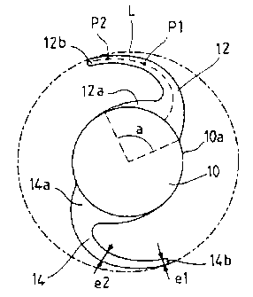
Referring firstly to Figures la and 1b, and to Figure 3, a first embodiment
of the one-piece, flexible intraocular implant will be described. As shown in
Figure
1 a, the intraocular implant is constituted by an optical portion 10 of
substantially
circular shape, limited by an anterior diopter and a posterior diopter and by
a
haptic portion constituted by two loops 12 and 14, these two loops being
identical
or substantially identical and connected to the periphery 10a of the optical
portion
at two substantially diametrally opposite points. These loops in C form
present a
curvature which varies regularly without presenting singular points.
According to an essential characteristic of the invention, the implant is in
one-piece, i.e. the optical portion 10 and the haptic loops 12 and 14
constitute only
one piece, this piece being a pHEMA, for example hydrogel. The modulus of
elasticity of the composition of pHEMA used is included between 0.25 MPa and 1
MPa. According to the particular embodiment described, the modulus of
elasticity
is preferably equal to 0.6 MPa. It is therefore seen that, to make the one-
piece
flexible implant, a type of pHEMA presenting a modulus of elasticity greater
than
the pHEMA conventionally used, is employed. However, by limiting the modulus
of elasticity to 1 MPa, there is still the possibility of bending the optics
easily and
of maintaining the optics bent with a force of hold compatible with the
surgical
operation.
In addition, as is seen, each loop 12 comprises a zone, a connecting end
12a which presents a considerable width with respect to the running part of
the
loop and which is therefore connected at an angle at the centre a of the
optical
portion which is relatively large, for example of the order of 80 degrees and
more
generally included between 60 and 90 degrees, and a second free end 12b
intended
CA 02253359 1998-11-02
6
it is placed in position in the eye, and of the variation of the inertia
moment at these two points
P2 and P1, is substantially constant.
To that end, and if a force exerted on the end of the loop is considered, then
the
bending moment will increase as one approaches the optics in substantially
linear fashion. It is
therefore question of varying the inertia moment in the same way. The inertia
moment will be
expressed in the following manner: I2 = Io + 1 x 0I.
lo is the inertia moment at the end of loop, l being the distance (in mm)
which separates
the end of the loop at the point in question, this distance being taken on
said neutral axis.
DI is the coefficient of variation of the inertia moment. This variation of
inertia moment
is expressed in mm'. 0I is preferably included between 5.10' mm3 and 15.10'
mm3.
Thanks to this arrangement, a curvature is thus obtained by regular bending of
the loop
when the implant is placed in position within the capsular sac. For example,
in Figure la-lb,
the diameter D 1 of the optical portion is 6 mm, while the external diameter
D2 of the haptic
portion at rest is equal to 12 mm.
Figure 3 shows the deformation of the loop when the implant is positioned in a
capsular
sac 20 of internal diameter 11 mm. It is seen that the bending of each loop,
instead of being
concentrated in the zones of connection 12a to 14a, is developed over the
whole of the length
of the loop 12-14, which makes it possible to have a considerable zone of
contact Z between
the part of the loop close to its free end 12b-14b with the internal wall of
the caspular sac.
It will be understood that this relatively large length of contact avoids a
localized
deformation of the capsular sac, due to the fact that the punctual pressure
applied is distributed
over the whole of the zone Z and not in a limited number of points, as in the
case of the
implants of the state of the art. In addition, this arrangement makes it
possible to avoid the
risks of perforation of capsular sac due to a considerable localized pressure.
Finally, as this
zone Z presents a relative long length, there is good abutment of each loop on
the internal wall
of the capsular sac and therefore a good hold of the optical portion in place.
In order to obtain this constancy or substantial constancy of the ratio of the
variation of
the bending moment applied to the loop on the
AMENDED SHEET
CA 02253359 1998-11-02
It will be understood that this relatively large length of contact avoids a
localized deformation of the capsular sac, due to the fact that the punctual
pressure
applied is distributed over the whole of the zone Z and not in a limited
number of
points, as in the case of the implants of the state of the art. In addition,
this
arrangement makes it possible to avoid the risks of perforation of capsular
sac due
to a considerable localized pressure. Finally, as this zone Z presents a
relative long
length, there is good abutment of each loop on the internal wall of the
capsular sac
and therefore a good hold of the optical portion in place.
In order to obtain this constancy or substantial constancy of the ratio of the
variation of the bending moment applied to the loop on the variation of the
inertia
moment, the loop preferably has in the optical plane, a width g which
decreases
from its connecting end 14a towards its free end 14b. Figure la shows a width
e1
close to the connecting zone equal to 0.55 mm and a width e2 at its end 14b
which
is 0.35 mm. As shown in Figure 1b, on the other hand, if the thickness d_ of
each
loop is considered, i.e. its dimension in the direction of the optical axis
XX', this
thickness d increases from the periphery of the optical portion towards the
free
end. In zone dl, this thickness is typically 0.35 mm, while at the free end
12b, this
thickness d2 is 0.45 mm. To that end, the inertia moment vanes as a function
of the
distance which separates the end of the loop with respect to the point in
question
on the neutral axis with a coefficient included between 5.10' and
15.10'°. The
moment is expressed in mm4 and the_distance in mm. _
Referring now to Figures 2a, 2b and 4a, 4b, a second embodiment of the
one-piece, flexible, intraocular implant according to the invention will be
described.
In this embodiment, each haptic loop 12, 14 and which has, in the running
part,
the same dimensions as the loops of the embodiments of Figure la, is completed
by
an additional arm respectively referenced 22, 24. Each arm 22, 24 also
comprises a
connecting end 22a at the periphery of the optical portion and a connecting
end
22b at the free end 12b of the associated loop. The arm 22 or 24 has a
substantially
constant width e' except, of course, in its connecting end part 22b where this
thickness is greater to ensure continuity with the loop 12, the width e' is
typically
CA 02253359 1998-11-02
8
equal to 0.25 mm. In this way, the assembly constituted by the loop 12 and the
arm
22 defines between these two elements a recess respectively referenced 26 and
28.
This improved embodiment presents all the advantages of the embodiment
of Figure la, concerning the bending qualities of the loops 12 and 14 proper
but,
in addition, the mechanical coupling of the arms 22 and 24 with the loops 12
and
14 makes it possible to avoid the risks of rotation of the optical portion 10,
by
reason of the risks of torsion of the loops 12 and 14, due to their being
constituted
by a relatively flexible material. In fact, the additional arms 22 and 24
being directly
connected to another zone of the periphery of the optical portion and to the
free
end of each loop, this movement of torsion is avoided or, at least, the risks
thereof
are considerably reduced.
Figures 4a and 4b show the positioning of the intraocular implant 10' of
Figure 2a in a capsular sac 20 of which the internal diameter is respectively
equal
to 11 mm for Figure 4a and 10 mm for Figure 4b. These Figures show in
particular
the deformation by bending of the loops 12 and 14 and of the arms 22 and 24.
It is
observed fat there is still a relatively large zone Z of contact between the
haptic
loops and the periphery 20 of the capsular sac, which, of course, presents the
same
advantages as those which were described in connection with Figure 3.
Figures Sa to Sc show the tests made respectively on a one-piece flexible
implant of the prior art (5a), and on the implants of Figure la (5b) and
Figure 2a
(5c). Each diagram represents the force of compression F as a function of the
external diameter D of the haptic portion, the diameter D at rest being equal
to 12
mm.
In the case of Figure Sa, it is seen that the force of compression is much
reduced while, in the case of Figures Sb and Sc, this force of compression is
much
higher for the same diameter, which ensures a much better holding in place of
the
optical portion in the eye.