Note : Les descriptions sont présentées dans la langue officielle dans laquelle elles ont été soumises.
CA 02253371 1998-11-02
PCT/US97106991
WO 97/41817
1
DIAPER HAVING AN IIVViPROVED LEG CUFF
s
lo FIELD OF THE INVENTION
The present invention relates to articles which absorb and/or contain bodily
exudates, including disposable absorbent articles such as diapers, adult
incontinence
products, sanitary napkins and the like. More particularly, the invention
relates to
disposable absorbent articles having stand-up leg cuffs with wide elasticized
skin
is contacting surfaces which provide improved fit and containment
characteristics.
BACKGROUND OF THE INVENTION
The major function of absorbent articles such as disposable diapers and adult
incontinent briefs, is to absorb and contain body exudates. Such articles are
also intended
2o to prevent body exudates from soiling, wetting, or otherwise contaminating
clothing or
other articles, such as bedding, that come in contact with the wearer. The
most common
mode of failure for such products occurs when body exudates leak out of the
gaps
between the article and the wearer's leg or waist to adjacent clothing because
they are not
immediately absorbed within the article. This is most evident with loose fecal
material
zs which is not easily absorbed by the absorbent article and tends to "float"
on the top surface
of the absorbent article.
Disposable diapers, such as those disclosed in U.S. Pat. No. 3,860,003 issued
to
Kenneth Barclay Buell on Jan. 14, 1975, generally have topsheet, a backsheet,
an
absorbent core, and elasticized leg flaps that improve the diaper's ability to
contain body
3o exudates. However, despite the effectiveness of such structures, body
exudates can leak
through the leg flaps and soil the wearer's clothing because the diaper does
not constrain
the free flow of such material or provide a structure to hold it within the
diaper so that as
such material flows freely on the surface of the topsheet, it tends to work
its way past the
elasticized leg flaps. To improve the containment characteristics of diapers
numerous
ss different leg cuff configurations have been identified. An example of an
absorbent
CA 02253371 2002-03-04
2
comprising leg cuffs with improved containment characteristics are described
in U.S.
Patent No. 4,808,177 issued to DesMarais et al. on Feb. 28, 1989. These
elasticized
leg cuffs prove effective generally to prevent wicking and overflow from the
fluid
laden diaper to clothing contacting the edges of the diaper in that the
elasticized leg
cuffs present a liquid impervious barrier between the edge of the diaper and
the
contacting clothing, and in addition, provide a gasketing action about the
legs of the
wearer. However, such elasticized leg cuffs have the tendency to indent and
mark the
skin because the elastic force is concentrated along a narrow elastic band,
resulting in
high localized pressures. Although attempts have been made; to address the
problem
of skin marking by utilizing wider elastics in the leg cuffs to reduce
localized pressure
where the cuffs contact the skin of the wearer, such attempts have not been
completely successful. Because the distal edge of the cuff is not controlled,
if the
diaper is put on incorrectly or if the wearer moves, the elastics may be
displaced from
their optimum position for containment and comfort and the wide surface of the
elastics may be presented at an angle or perpendicular to the skin. This
results in the
elastic force being concentrated at the edge of the elastic (or at the folded
edge should
the elastomeric buckle) rather than spread across the wide surface of the
elastic. As
such, the effectiveness of the cuff and its comfort may be substantially
decreased
leading to skin marking and irritation.
Therefore, it is an object of an aspect of the present invention to provide an
absorbent article which has improved comfort and containment characteristics.
It is also an object of an aspect of the present invention to provide an
absorbent article having a standing cuff which acts as a restraint against the
leakage of
body exudates without marking or irritating the skin of the wearer.
A further object of an aspect of the present invention is to provide standing
elasticized leg cuffs having a wide elasticized skin-contacting surface.
Yet another object of an aspect of the present invention is to provide
elasticized leg cuffs wherein the edges of the wide elasticized region are
controlled.
A still further object of an aspect of the present invention is provide a wide
elasticized skin-contacting surface which is presented parallf;l to the
wearer's skin
throughout the dynamic range of baby motions.
SUMMARY OF THE INVENTION
The present invention provides a disposable absorbent article to be fitted to
a
wearer having a front waist region, a rear waist region, a crotch region
disposed
between the front waist region and the rear waist region, a longitudinal
centerline and
a lateral
CA 02253371 2002-03-04
centerline. The absorbent article includes a topsheet, a backsheet joined with
the
topsheet, and an absorbent core disposed between the topshc;et and the
backsheet, the
absorbent core having a pair of opposed longitudinal edges.
The absorbent article also includes a leg cuff extending at least laterally
outwardly from each opposed longitudinal edge. Each leg cuff preferably has an
inner
surface and an opposed outer surface, a proximal edge, a distal edge and an
elasticized
region disposed between the proximal edge and the distal edge. The elasticized
region
has an inner edge, an outer edge disposed laterally outwardly from the inner
edge and
a width of between about 3mm and about 1 Smm. The proximal edge of each leg
cuff
to preferably extends generally longitudinally along and adjacent to at least
a portion of
one of the opposed longitudinal edges. The distal edge of each of said leg
cuffs is
preferably disposed laterally outwardly from the proximal edge.
Each leg cuff preferably includes an inner bond disposed adjacent at least a
portion of the proximal edge of each leg cuff. The inner bond preferably joins
the leg
cuff to the underlying structure of the absorbent article. An outer bond is
spaced
laterally outwardly from the imaer bond, the spacing between the inner bond
and the
outer bond defining a leg cuff base width. The outer bond preferably joins at
least a
portion of the leg cuff adjacent the distal edge to the absorbent article.
An inner wall of each leg cuff extends upwardly and laterally outwardly from
2o the inner bond to the inner edge of the elasticized region. The inner wall
has a first
height of between about 30mm and about 80mm. An outer wall which extends
upwardly and laterally inwardly from the outer bond to the outer edge of the
elasticized region. The outer wall has a second height of between about l5mm
and
about SOmm.
An elastic element is preferably disposed in the elasticized region of each
leg
cuff. The elasticized region of the leg cuff is preferably provided generally
parallel to
the wearer's skin when the absorbent article Is fitted to the wearer.
In accordance with one embodiment of the present invention, there is provided
a disposable absorbent article to be fitted to a wearer having a front waist
region, a
3o rear waist region, a crotch region disposed between the front waist region
and the rear
waist region, a longitudinal centerline and a lateral centerline, the
absorbent article
comprising:
a topsheet;
a backsheet joined with the topsheet;
an absorbent core disposed between the topsheet and the backsheet, the
absorbent core having opposed longitudinal edges; and
CA 02253371 2002-03-04
3a
a leg cuff extending at least laterally outwardly from each the opposed
longitudinal edge, each the leg cuff having an inner surface, an outer surface
opposed to the inner surface, a proximal edge, a distal edge and an
elasticized
region disposed between the proximal edge and the distal edge, the elasticized
region having an inner edge, an outer edge disposed laterally outwardly from
the inner edge and a width, each the proximal edge extending generally
longitudinally along and adjacent to at least a portion of one of the opposed
longitudinal edges, the distal edge of each of the leg cuffs disposed
laterally
outwardly from the proximal edge of the leg cuff; the disposable absorbent
to article wherein at least a portion of the leg cuff comprises:
an inner bond overlying the core and disposed adjacent at least a
portion of the proximal edge of each the leg cuff, the inner bond
joining the leg cuff to the absorbent article;
an outer bond spaced laterally outwardly from the inner bond, the
15 spacing between the inner bond and the outer bond defining a leg cuff
base width, the outer bond joining at least a portion of the leg cuff
adjacent the distal edge to the absorbent article,
an inner wall extending upwardly and laterally outwardly from the
inner bond to the inner edge of the elasticized region,
20 an outer wall extending upwardly and laterally inwardly from the outer
bond to the outer edge of the elasticized region, and
an elastic disposed in the elasticized region of the leg cuff;
and the elasticized region of the leg cuff being provided generally
parallel to the wearer's skin when the absorbent article is fitted to the
25 wearer.
BRIEF DESCRIPTION OF THE DRAWINGS
While the specification concludes with claims particularly pointing out and
distinctly claiming the subject matter which is regarded as the present
invention, it is
3o believed that the description will be better understood from the following
descriptions
which are taken in conjunction with the accompanying drawings in which like
designations are used to designate substantially identical elements, and in
which:
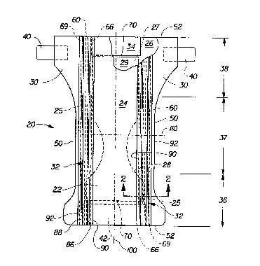
Figure 1 is a plan view of an absorbent article embodiment of the present
invention having portions cut away to reveal the underlying ;structure, the
body-facing
35 surface of the
CA 02253371 1998-11-02
WO 97!41817 PCT/US97/06991
4
diaper facing the viewer;
Figure 2 is a fragmentary cross-sectional view taken along section line 2-2 of
Figure 1;
Figure 3 is a fragmentary cross-sectional view of an alternative embodiment of
the
s invention;
Figure 4 is a fragmentary cross-sectional view of one embodiment of the cuff
of the
present invention;
Figure 5 is a fragmentary cross-sectional view of one embodiment of the cuff
of the
present invention;
~o Figure 6 is a fragmentary cross-sectional view of one embodiment of the
cuff of the
present invention.
DETAILED DESCRIPTION OF THE INVENTION
As used herein, the term "absorbent article" refers to devices which absorb
and
~s contain body exudates, and, more specifically, refers to devices which are
placed against or
in proximity to the body of the wearer to absorb and contain the various
exudates
discharged from the body. The term "disposable" is used herein to describe
absorbent
articles which are not intended to be laundered or otherwise restored or
reused as an
absorbent article (i.e., they are intended to be discarded after a single use
and, preferably,
zo to be recycled, composted or otherwise disposed of in an environmentally
compatible
manner}. A "unitary" absorbent article refers to absorbent articles which are
formed of
separate parts united together to form a coordinated entity so that they do
not require
separate manipulative parts like a separate holder and liner. A preferred
embodiment of an
absorbent article of the present invention is the unitary disposable absorbent
article, diaper
zs 20, shown in Figure 1. As used herein, the term "diaper" refers to an
absorbent article
generally worn by infants and incontinent persons that is worn about the lower
torso of the
wearer. It should be understood, however, that the present invention is also
applicable to
other absorbent articles such as incontinence briefs, incontinence
undergarments, diaper
holders and liners, feminine hygiene garments, and the like.
3o Figure 1 is a plan view of the diaper 20 of the present invention in its
flat-out,
uncontracted state (i.e., with elastic induced contraction pulled out) with
portions of the
structure being cut-away to more clearly show the construction of the diaper
20 and with
the portion of the diaper 20 which faces or contacts the wearer oriented
towards the
viewer. As shown in Figure 1, the diaper 20 preferably comprises a liquid
pervious
3s topsheet 24; a liquid impervious backsheet 26 joined with the topsheet 24;
an absorbent
CA 02253371 2002-03-04
core 28 positioned between the topsheet 24 and the backsheet 26; side panels
30;
elasticized leg cuffs 32; an elastic waist feature 34; and a fastening system
including at
least one engaging component 40 and at least one landing component 42. The
diaper 20 is
shown in Figure 1 to have a first waist region 36, a second waist region 38
opposed to the
s first waist region 36, a crotch region 37 positioned between the first waist
region 36 and
the second waist region 38, and a periphery which is defined by the outer
edges of the
diaper 20 in which the longitudinal edges 50 run generally parallel to the
longitudinal
centerline 100 of the diaper 20 and the end edges 52 run between the
longitudinal edges 50
generally parallel to the lateral centerline 110 of the diaper 20.
lo Figure 1 shows a preferred embodiment of the diaper 20 in which the
topsheet 24
and the backsheet 26 have length and width dimensions generally larger than
those of the
absorbent core 28. The topsheet 24 and the backsheet 26 e~ntend beyond the
edges of the
absorbent core 28 to thereby form the periphery of the diaper 20. While the
topsheei 24,
the backsheet 26, and the absorbent vote 28 may be assembled in a variety of
well known
~s configurations, preferred diaper configurations are described generally in
U.S. Patent
3,860,003 entitled "Contractible Side Portions for Disposable Diaper" which
issued to
Kenneth B. Buell on January 14, 1975; and U.S. Pat. No. 5,151,092 issued to
Buell on
September 9, 1992; and U.S. Pat. No. 5,221,274 issued to Buell on June 22,
1993.
so Figure 2 is a fragmentary cross-sectional view of the diaper 20 taken along
section
line 2-2 of Figure 1. The containment assembly 22 of the diaper 20 is shown in
Figure l as
comprising the main body (chassis) of the diaper 20. The containment assembly
22
comprises at least as absorbent core 28 and preferably an outs covering layer
comprising
the topshett 24 snd the badcsheat 2b. When the absorbent article comprises a
separate
xs holder and a liner, the containment asxmbly 22 generally comprises the
holder and the
liner (i.~, the coatainmmt assanbiy 22 comprises one or more layers of
material to define
the holder while the lictex comprises as absorbent composite such as a
topsheet, a
backsheet, and sn absorbent core.) For unitary absorbent amides, the
containment
assembly 22 comprises the main stnrcture of the diaper with other features
added to form
xo the composite diaper strucdue. Thus, the containment assanbly 22 for the
diaper 20
generally comprises the topsheet 24, the backshed 25, and the absorbent core
28.
The absorbent core 28 may be ~ any absorbent means which is generally
compressible, conformable, norrirritating to the wearer's skin, and capable of
absorbing
and retaining liquids such as urine and other certain body aeudates. ~As shown
in Figure 1,
as the absorbent core 28 has longitudinal edges 25, a garment surface 27 and a
body surface
CA 02253371 2002-03-04
6
29. 'The absorbent core 28 may be manufactured in a wide variety of sizes and
shapes
(e.g., rectangular, hourglass, "T"-shaped, asymmetric, ere.) and from a wide
variety of
liquid-absorbent materials commonly used in disposable dispers and other
absorbent
articles such as comminuted wood pulp, which is generally referred to as
airfelt. Examples
s of other suitable absorbent materials include creped cellulose wadding;
meltbfown
polymers, including coform; chemically stiffened, modified or cross-finked
cellulosic fibers;
tissue, including tissue wraps and tissue laminates; absorbent foams;
absorbent sponges;
superabsorbent polymers; absorbent gelling materials; or any other known
absorbent
material or combinations of materials.
io The configuration and construction of the absorbent core 28 may also be
varied
(e.g., the absorbent core may have varying caliper zones, a hydrophilic
gradient, a
superabsorbent gradient, or lower average density and lower average basis
weight
acquisition zones; or may comprise one or more layers or stnrcdrres). The
total absorbent
capacity of the absorbent core 28, however, should be compatible with the
design loading
is ark the intended use of the diaper 20. Further, the size and absorbent
capacity of the
absorbent core 28 may be varied to uxonurwdate wearers ranging from infants
through
adults. Exemplary absorbent structures for use as the absorbent core 28 are
described in
U.S. Patent 4,610,678 entitled "~lgh-Density Absorbent Structures" issued to
Weisman et
al. on September 9, 1986; U.S. Patent 4,673,402 entitled "Absorbent Articles
W;th Dual-
Zo Layered Cores" issued to Weisman et al. on June 16, 1987; U.S. Patent
4,888,231 entitled
"Absorbent Core Having A Dusting Layer" issued to Angstadt on December 19,
1989; and
U.S. Patent 4,834,735, entitled "I~gh Deity Absorbent Members Having Lower
Density
and6Lower Ba:is Weight Acquisition Zones", issued to Alemany et al. on May 30,
1989.
is Tlwr backsheu 26 is preferably impervious to liquids (e.g., urine) and is
preferably
marrufacturod frmn s thin pkstic film, ahhovgh other flexible liquid
impervious materials
may also be used. ('The teen "8exr'bk" refers to materials which ue compliant
and will
readily conform to the general shape and contours of the human body.) The
backsheet 26
prevents the exudates adsorbed and comair~ in the absorbent core 28 from
wetting
o articles which contact the diaper 20 such as bedshetts and undergarments.
Thus, the
backsheet 26 may comprise s woven or nonwoven material, polymeric films such
as
thermoplastic films of polyethylene or polypropylene, or composite materials
such as a
film-coated nonwoven material. Preferably, the backsheet is a thermoplastic
film having a
thickness of about 0.012 mm (0.5 mil) to about 0.051 mm (2.0 mils).
Particularly
3s preferred materials for the backsheet include blown films and cast films as
manufactured by
CA 02253371 2002-03-04
Tredegar Industries, Inc. of Terre Haute, IN, under the trade names RR8220 and
RR5475, respectively. The backsheet 26 is preferably embo ssed and/or matte
finished
to provide a more clothlike appearance. Further, the backsheet 26 may permit
vapors
to escape from the absorbent core 28 (i.e., breathable) while still preventing
exudates
from passing through the backsheet 26.
The backsheet 26 may be elastically extensible in one or more directions. In
one embodiment, the backsheet 26 may comprise a structural elastic-like film
(SELF)
web. A structural elastic-like film web is an extensible mate~aal that
exhibits an
elastic-like behavior in the direction of elongation without the use of added
elastic
to materials. The SELF web includes a strainable network having at least two
contiguous, distinct, and dissimilar regions. One of the regions is configured
so that it
will exhibit resistive forces in response to an applied axial elongation in a
direction
parallel to the predetermined axis before a substantial portion of the other
region
develops significant resistive forces to the applied elongation. At least one
of the
1 s regions has a surface-pathlength which is greater than that of the other
region as
measured substantially parallel to the predetermined axis while the material
is in an
untensioned condition. The region exhibiting the longer surface-pathlength
includes
one or more deformations which extend beyond the plane of the other region.
The
SELF web exhibits at least two significantly different stages of controlled
resistive
2o force to elongation along at least one predetermined axis when subjected to
an applied
elongation in a direction parallel to the predetermined axis. The SELF web
exhibits
first resistive forces to the applied elongation until the elongation of the
web is
sufficient to cause a substantial portion of the region having the longer
surface-
pathlength to enter the plane of applied elongation, whereupon the SELF web
exhibits
2s second resistive forces to further elongation. The total resistive forces
to elongation
are higher than the first resistive forces to elongation provided by the first
region.
SELF webs suitable for the present invention are more completely described in
the
U.S. Patent 5,518,801 entitled ''Web Materials Exhibiting Elastic-Like
Behavior"
filed in the name of Chappell, et, al. {PCT Publication No. WO 95/03765
published
3o February 9, 1995). In alternate embodiments, the backsheet 26 may comprise
elastomeric films, foams, strands, or combinations of these or other suitable
materials
with nonwovens or synthetic films.
The backsheet 26 is positioned adjacent the garment surface 27 of the
absorbent core 28 and is preferably joined thereto by attachment means such as
those
35 well known in the art. {As used herein, the term "joined" encompasses
configurations
whereby an element is directly secured to another element by affixing the
element
directly to the other
CA 02253371 2002-03-04
8
element, and configurations whereby an element is indirectly secured to
another
element by affixing the element to intermediate members) which in turn are
affixed
to the other element.) For example, the backsheet 26 may be. secured to the
absorbent
core 28 by a uniform continuous layer of adhesive, a patterned layer of
adhesive, or
an array of separate lines, spirals, or spots of adhesive. Adhesives which
have been
found to be satisfactory are manufactured by H. B. Fuller Company of St. Paul,
Minnesota and marketed as HL-1258. One preferred attachment means comprises an
open pattern network of filaments of adhesive as disclosed in U.S. Patent
4,573,986
entitled "Disposable Waste-Containment Garment", which issued to Minetola et
al. on
1o March 4, 1986. More preferably the attachment means will include several
lines of
adhesive filaments which are swirled into a spiral pattern, as is illustrated
by the
apparatus and methods shown in U.S. Patent 3,911,173 issued to Sprague, Jr. on
October 7, 1975; U.S. Patent 4,785,996 issued to Ziecker, et al. on November
22,
1978; and U.S. Patent 4,842,666 issued to Werenicz on June 27, 1989.
Alternatively,
the attachment means may comprise heat bonds, pressure bonds, ultrasonic
bonds,
dynamic mechanical bonds, or any other suitable attachment. means or
combinations
of these attachment means as are known in the art.
The topsheet 24 is positioned adjacent the body surface 29 of the absorbent
core 28 and is preferably joined thereto and to the backsheet 26 by attachment
means
2o such as those well known in the art. Suitable attachment means are
described with
respect to joining the backsheet 26 to the absorbent core 28. In a preferred
embodiment of the present invention, the topsheet 24 and the; backsheet 26 are
joined
directly to each other in the diaper periphery and are indirectly joined
together by
directly joining them to the absorbent core 28.
The topsheet 24 is preferably compliant, soft feeling, and non-irritating to
the
wearer's skin. Further, the topsheet 24 is preferably liquid pervious,
permitting liquids
(e.g., urine) to readily penetrate through its thickness. A suitable topsheet
24 may be
manufactured from a wide range of materials, such as porous foams; reticulated
foams; apertured plastic films; or woven or nonwoven webs of natural fibers
(e.g.,
3o wood or cotton fibers), synthetic fibers (e.g., polyester or polypropylene
fibers), or a
combination of natural and synthetic fibers. Preferably, the topsheet 24 is
made of a
hydrophobic material to isolate the wearer's skin from liquids contained in
the
absorbent core 28. There are a number of manufacturing techniques which may be
used to manufacture the topsheet 24. For example, the topsheet 24 may be a
nonwoven web of fibers spunbond, carded, wet-laid, meltblown, hydroentangled,
combinations of the above, or the like. One preferred
CA 02253371 2002-03-04
9
topsheet 24 comprises a web of staple length polypropylene fibers such as is
manufactured
by Veratec, Inc., a Division of Intennational Paper Company, of Walpole,
Massachusetts
under the designation P-8.
The diaper 20 preferably further comprises an elastic waist feature 34 that
provides
s improved fit and containment. The elastic waist feature 34 is that portion
or zone of the
diaper 20 which is intended to elastically expand and contract to dynamically
fit the
wearer's waist. The elastic waist feature 34 at least extends longitudinally
outwardly from
at least one of the waist edges 70 of the absorbent core 28 and generally
forms at least a
portion of the end edge 52 of the diaper 20. Disposable diapers are generally
constructed
~o so as to have two elastic waist features, one positioned in the first waist
region 36 and one
positioned in the second waist region 38, although diapers can be constructed
with a single
elastic waist feature. Further, while the elastic waist feature 34 or any of
its constituent
elements can comprix a xpante element affixed to the diaper 20, the elastic
waist feature
34 is preferably constructed as an extension of other dements of the diaper
20, such as the
~s backsheet 26, the topsheet 24, or both the backsheet 26 and the topsheet
24.
The elastic waist feature 34 may be constructed in a number of different
configurations including thox described in U.S. Patent 4,515,595 issued to
Kievit et al. on
May 7, 1985 and the above referet~ed U.S. Pat. No 5, 151,092 issued to Budl on
September 9, 1992; and U.S. Pat. No. 5,221,274 issued to Buell on June 22,
1993 .
so
The diaper 20 preferably also comprixs a fasterrirtg system. The fastening
system
preferably maintains the first waist region 36 and the xcond waist region 38
in an
overlapping configuration so as to provider lateral tensions about the
circumference of the
dispa~ 20 to hold the diaper 20 on the wearer. The .fastening system
preferably cornprixs
~s tape tabs md/or hook and loop fastening components. In one preferred
embodiment, as
shown i4 >a 1, the f~irrg systan includes eagagi'rg components 40 disposed in
said
second want region 38 genaxliy along acid longitudinal edges 50 of the diaper
and landing
zone 42 dispoxd in the front waist region 36 adjacent said end edge 52. (As
used herein,
the term "dispoxd" is used to mean that an dements) of the diaper is formed
(joined and
3o positioned) in a ~iarlar place or position as a unitary struadrre with
other dements of
the diaper or as a separate dement joined to another dement of the diaper.)
Exemplary
fastening systems are dixlosed in U.S. Patent 4,846,815 entitlod "Disposable
Diaper
Having An Improved Fastening Device" issued to Scripps on July 11, 1989; U.S.
Patent
4,894,060 entitled "Disposable Diaper With Improved Hook Fastener Portion"
issued to
3s Nestegard on Jatwary 16, 1990; U.S. Patent 4,946,527 entitlod "Pressure-
Sensitive
CA 02253371 2002-03-04
Adhesive Fastener And Method of Making Same" issued to Battrell on August 7,
1990; U.S. Patent 3,848,594 entitled "Tape Fastening System for Disposable
Diaper"
issued to Buell on November 19, 1974; US. Patent BI 4,662,875 entitled
"Absorbent
Article" issued to Hirotsu et al. on May 5, 1987; and the hereinbefore
referenced U.S.
5 Pat. No. 5,1 S 1,092 issued to Buell on September 9, 1992; and U.S. Pat. No.
5,
221,274 issued to Buell on June 22, 1993.
The diaper 20 may also comprise side panels 30. The; side panels 30 may be
elastic or extensible to provide a more comfortable and contouring fit by
initially
conformably fitting the diaper to the wearer and sustaining this fit
throughout the time
to of wear well past when the diaper has been loaded with exudates since the
elasticized
side panels 30 allow the sides of the diaper to expand and contract. The side
panels 30
may also provide more effective application of the diaper 20 because even if
the
diaperer pulls one elasticized side panel 30 farther than the other during
application
(asymmetrically), the diaper 20 will "self adjust" during wear.
While the diaper 20 of the present invention preferably has the side panels 30
disposed in the second waist region 38; the diaper 20 may bc~ provided with
side
panels 30 disposed in the first waist region 36 or in both the first waist
region 36 and
the second waist region 38. The side panels 30 may be constructed in any
suitable
configurations. Examples of diapers with elasticized side panels are disclosed
in U.S.
2o Patent 4,857,067, entitled "Disposable Diaper Having Shirrc;d Ears" issued
to Wood,
et al. on August 15, 1989; U.S. Patent 4,381,781 issued to Sciaraffa, et al.
on May 3,
1983; U.S. Patent 4,938,753 issued to Van Gompel, et al. on July 3, 1990; and
the
hereinbefore referenced U.S. Pat. No. 5,151,092 issued to Buell on September
9,
1992; and U.S. Pat. No. 5, 221,274 issued to Buell on June 2;2, 1993.
The diaper 20 preferably further comprises leg cuffs 32 which provide
improved containment of liquids and other body exudates. Leg cuffs may also be
referred to as leg bands, side flaps, barrier cuffs, or elastic cuffs. L1.S.
Patent
3,860,003 describes a disposable diaper which provides a contractible leg
opening
having a side flap and one or more elastic members to provide an elasticized
leg cuff
(gasketing cuff). U.S. Patent 4,909,803 entitled "Disposable Absorbent Article
Having Elasticized Flaps" issued to Aziz et al. on March 20, 1990, describes a
disposable diaper having "stand-up" elasticized flaps (barrier cuffs) to
improve the
containment of the leg regions. U.S. Patent 4,695,278 entitled "Absorbent
Article
Having Dual Cuffs" issued to Lawson on September 22, 1987,
CA 02253371 1998-11-02
WO 97/41817 PCT/US97/06991
11
describes a disposable diaper having dual cuffs including a gasketing cuff and
a barrier
cuff.
In preferred embodiments, the leg cuffs 32 extend generally longitudinally
from the
front waist region 36 through the crotch region 37 to the rear waist region
38. Although
s the cuffs 32 may extend from one end edge 52 of the diaper 20 to the
opposite end edge
52, it is not necessary that they do so. Further, although the cuffs 32 are
preferably
structurally mirror images of each other, the cuffs 32 may be configured
differently. In any
case, preferably one leg cuff 32 extends laterally outwardly from each
longitudinal edge of
the core 25. It is also preferred that at least a portion of each leg cuff 32
is bonded sealed
lo or joined in or adjacent the front waist region 36 and the rear waist
region 38 to prevent
any liquids that may pass through the inner wall 80 of the cuff 32 from
channeling along
the interior of the leg cuff 32 and being directed out of the diaper 20 in the
front or rear
waist regions 36 and 38.
With reference to Figures 2-6 the leg cuffs 32 of the present invention each
have a
~s proximal edge 90 and a distal edge 92. Each proximal edge 90 extends
generally
longitudinally along and adjacent to at least a portion of one of the
longitudinal edges 25
of the absorbent core 28. The distal edge 92 of each leg cuff 32 is disposed
laterally
outwardly of its corresponding proximal edge 90. (As used herein, the terms
"laterally
inboard" or "laterally inwardly" refer to relative locations which are closer
to the
zo longitudinal centerline 100 than another location to which the laterally
inboard location is
being compared. The terms "laterally outboard" or "laterally outwardly" refer
to relative
locations that are farther away from the longitudinal centerline 100 of the
diaper 20 than
other locations to which the laterally outboard location is being compared.)
Each leg cuff
32 comprises an inner wall 80, an outer wall 82, and a generally fiat
elasticized region 84
zs that spans between the inner wall 80 and the outer wall 82 defining a width
W. The
elasticized region 84 has an inner edge 86 and an outer edge 88. The inner
wall 80 is that
portion of the leg cuff 32 which extends upwardly away from the chassis 22 of
the diaper
20 and laterally outwardly from the inner bond 66 to the elasticized region 84
of the leg
cuff 32 when the cuff 32 is in a contracted, stand-up configuration. The outer
wall 82
3o extends upwardly away from the chassis 22 of the diaper 20 and laterally
inwardly from
the outer bond 69 to the elasticized region 84 of the leg cuff 32 when the
cuff 32 is in a
contracted, stand-up configuration. As shown in Figure 4, the length (or
height) HI of the
inner wall 80 is measured from the bond 66, which joins the inner wall 80 to
the underlying
structure of the diaper 20, to the inner edge 86 of the elasticized region 84.
The length (or
ss height) H2 of the outer wall 82 is measured from the outer bond 69, which
joins the outer
CA 02253371 2002-03-04
12
wall 82 to the underlying structure of the diaper 20, to the outer edge 88 of
the elasticized
region 84.
Although an approximation of the length H I and H2 can be obtained by
measuring
the leg cuff 32 as it stands up in normal use, a more accurate measurement may
be
s obtained by removing the cuff 32 from the diaper 20 and placing it flat on a
relatively
planar surface before measuring the length H1 and H3. Relative to one another,
the inner
wall 80 of each leg cuff 32 is preferably disposed laterally inwardly of the
corresponding
outer wall 82, as shown in Figures 2-6. It should be noted, however, that
embodiments
are contemplated wherein at least a portion of the inner wall 80 may be
disposed laterally
no outwardly from at least a portion of the corresponding outer wall 82.
The leg cuffs 32 may comprise s single lamina or may comprise a laminate of
more
than one lamina. The laminae may be generally coextensive ar rnay be of
different size or
shape. Further, the lamina may be directly or indirectly joined to each other
with
continuous or intermittent bonding means as are known in the art. One example
of a leg
is cuff 32 comprising a laminate of more then one lamina is shown in Figure 5.
First laminate
54 is shown to be generally coextensive with second laminate 55. Elastic
element 60 is
shown to be disposed between the laminae, however, embodiments are
contemplated
wherein the elastic element 60 is disposed and/or joined to either surface of
the first
laminate 54 or the second laminate 55.
xo The materials that true up the inner and outer walls, 80 and 82, of the leg
cuffs 32
preferably comprise soft, compliant, air-permeable, hydrophobic materials such
as
nonwovens, formed films, tnicroporoua films, or foams. One preferred material
is a
hydrophobic potypropytate nonwoven having a basis weight of 20 grams per
square yard,
avaiiabk~rom Veratec, Inc. of Walpole, MA under the trade designation P-8.
is 'TES leg cuffs 32 tire mairttairted in their stand-up can5guration, away
from the
chassis 2I of the diaper 20 by an elastic element 60, as shown in Figures 2-6
(Although
inelastic rtes may be utilized to provide the leg cuffs 32 in their stand-up
configurations,
such means are less dairabk thin elastomeric mans due to the fact that
inelastic means
will gataaily not be abk to conform as well to the body of the wearer as
elastomeric
3o means, especially when the wears rrmves. As uxd heroin, the term
"elastomeric" refers to
materials which extend in at Idtst one direction when a stretching force is
applied to the
material, and then return to approximately their original dimensions after the
force is
removed.) The elastic eldnent 60 may comprix any one or more elastomeric
materials as
are known in the art, including rubber or synthetic nrbba, elastomeric Kratori
based films,
3s other elastomeric filrtts, elastomeric foams as well as any other known
elastomeric
* - Trade-mark
CA 02253371 2002-03-04
13
materials or combinations thereof. One exemptary elastomeric material is a
strand of
woven material comprising 12% Lycra and 88% nylon manufactured by Rainwood
Corp.
of Tupelo, MS.
Each elastic element 60 preferably comprises a single dastomeric member 62,
s however, multiple dastomeric members 62 may be usod. One example of multiple
elastomeric members 64 is shown in Figure 3. In multiple elastomeric member
embodiments, the elastomeric mernbera ba may be joined to each other or may
remain
separate members. Further, the elastic demem 60 may extend throughout the
entire length
of tht cuff 32 or may be limited to specific portions of the cuff 32. In
preferred
lo embodiments, the elastic element 60 is configured such that at least the
portion of the cuffs
32 disposed in the crotch region 37 stands up away from the underlying
structure of the
diaper 20 while in use.
'The elastomeric members) 62 or b4 provide tl~ elasticized region 84 of the
leg
cuff 32 with a width W. In embodiments including a single dastomeiic member 62
the
is width W corresponds generally with the distance between the laterally
inboard most edge
94 of the elastomeric member 62 and the laterally outboard most edge 96 of the
elastomeric member 62. In multiple dastomeric mesa embodiments, the width W
generally corresponds to the distance between the laterally inboard most
elastic 63 and the
laterally outboard most elastic 65, ss shown in Figure 3. In any embodiment,
the width W
so is preferably between at least about 3mm and about l5mm. Morc preferably,
width W is
between about Snun and about 8mm. It has been found that such widths help to
distribute
the forces provided by the dastomaic manber(s) 62, 64 ova a relatively wider
region
than conventional leg cuffs 32 without providing any additional irritation to
the wearer.
Thus; the ov~aall comfort of the article is improved and the poss<'bility and
extent of red
x3 IIISTlmlg It t.
T~ iatgth (or height) of the inner and outer walls 80 and 82 have been found
to be
important in order to allow the elastic elm 60 to conform to the shape and
curvature of
the wara's body while maintaining the da:ticired region 84 of the kg cuff 32
in an
orientation parallel to the wearers skin. It is desirable to maintain the
elasticized region 60
3d parallel to the skin of the wearer throughout the time the diaper 20 is
being worn to
improve the containment characteristics of the leg cuffs 32 and to reduce the
likelihood
and attest of marking gaia~atly associated with the leg cuffs 32 being in
contact with the
skin of the wearer. White it is recognized that the most desirable lengths for
the inner and
outer walls 80 and 82 of each cuff will vary depending on the wearer and the
specific
3s diaper design, in general, the length Hl of the inner wall 80 is preferably
greater than the
= Trade-mark
CA 02253371 1998-11-02
WO 97/41817 PCTIUS97106991
14
length H2 of outer wall 82. Preferably, the ratio of HI/H2 is between about
1.25 and 2.5,
and more preferably between about 1.3 and about 2Ø In one preferred
embodiment, each
leg cuff inner wall 80 preferably has a length Hl which is between at least
about 30 mm
and about 80 mm and each leg cuff outer wall 82 preferably has a length H2
which is
s between at least about 15 mm and about SOmm. More preferably, each leg cuff
inner wall
80 has a length H1 between about 45 mm and about 65 mm and each leg cuff outer
wall
82 preferably has a length H2 between about 25 mm and about 40 mm.
The leg cuffs 32 may be constructed in any number of suitable configurations.
Figures 2-6 illustrate three different preferred configurations. In Figure 2,
the inner wall
lo 80 comprises a separate material from that of the outer wall 82. The
materials comprised
in each wall are shown to be joined together in an overlapping configuration.
In such
configurations, the inner wall 80 and the outer wall 82 surround the elastic
element 60. In
a particularly preferred embodiment, as shown in Figure 2, the elastic element
60 is
disposed in the elasticized region 84 between the material comprised in the
inner wall 80
~s and the material comprised in the outer wall 82. The overlapping materials
may be
reversed from the configuration shown in Figure 2 in order to provide
different
containment and/or skin friendliness characteristics.
Alternatively, the elastic element 60, or any portion thereof, may be joined
to the
inner surface 67 or to the outer surface 68 of the cuff 32. In Figure 3, the
elastic element
Zo 60 comprising a plurality of elastic members 64 is disposed adjacent the
outer surface 68
of the cuff 32. Although it may be desirable to join some or all of the
elastic members 64
comprised in the elastic element 60, or portions thereof, it is not necessary
to do so.
Further, a single undivided material may make up the entire length of both the
inner wall
80 and the outer wall 82, or any portion of the inner wall 80 and/or the outer
wall 82. The
is whole elastic element 60 or any portion thereof may be wrapped in or
covered with
another material or materials. Such materials) may reduce the possibility of
delamination
of the elastomeric from the cuff 32 in configurations where it is joined
thereto.
As shown in Figure 6, at least a portion of the inner wall 80 may be joined,
directly
or indirectly, to at least a portion of outer wall 82. In the embodiment
shown, the inner
so wall 80 and the outer wall 82 completely surround the elastic element 60.
The bond 56
which joins the inner waD 80 and the outer wall 82 may comprise any means
known in the
art, including those mentioned herein with regard to inner and outer bonds 66
and 69.
In any configuration, the cuff wall materials may be joined to each other or
to the
elastic element 60 by any means known in the art, including adhesives,
ultrasonic bonding,
ss heat, pressure or any other known bonding means or combination of bonding
means. In
CA 02253371 1998-11-02
WO 97141817 PCT/US97/06991
preferred embodiments, an adhesive bond is employed. One exemplary adhesive is
available from Findley Adhesives Corporation of Wauwatosa, WI under the trade
designation Findley Adhesive 2031.
The inner and outer walls 80 and 82 may also be joined to the underlying
structure
s of the diaper 22 by any joining means known in the art, including those
mentioned herein.
In one preferred embodiment, the inner bond 66 joins the inner wall 80 of the
cuff 32 to
the underlying structure of the diaper 20 laterally inboard of the
longitudinal edge 25 of the
core 28 and the outer bond 69 joins the outer wall 82 of the cuff 32 to the
underlying
structure of the diaper 20 laterally outboard of the longitudinal edge 25 of
the core 28.
to However, embodiments are contemplated wherein the inner wall 80 is joined
to the
underlying structure of the diaper 20 laterally outboard of the longitudinal
edge 25 of the
core 28 and the outer wall 82 is joined to the underlying structure of the
diaper 20 laterally
outboard of the longitudinal edge 25 of the core 28, or wherein the inner wall
80 is joined
to the underlying structure of the diaper 20 laterally inboard of the
longitudinal edge 25 of
is the core 28 and the outer wall 82 is joined to the underlying structure of
the diaper 20
laterally inboard of the longitudinal edge 25 of the core 28. In any case, the
inner bond 66
is preferably disposed adjacent at least a portion of the proximal edge 90 of
the leg cuff 32
and the outer bond 69 is spaced laterally outwardly form the inner bond 6b.
The distance
between the bonds 66 and 69 defines the width of the base of the cuff 32,
which is
zo designated B (shown in Figure 4).
As with the width W, and the length H1 and HZ of each inner and outer wall, 80
and 82, it has been found that the spacing B between the inner bond 66 and the
outer bond
69 is an important factor contributing to the performance of each leg cuff 32.
While the
preferred spacing B between the bonds 66 and 69 is dependent on the particular
inner and
2s outer cuffwall heights (H1 and H2), generally the spacing B between the
bonds 66 and 69
is increased as the wall length Hl and H2 are increased. In preferred
embodiments
wherein the length H1 of the inner walls 80 ranges between about 30 mm and
about 80
mm the length H2 of the outer walls 82 ranges between about 15 mm and about
50mm, B
is preferably at least about 10 mm and more preferably at least about 15 mm.
so The diaper 20 is preferably applied to a wearer by positioning one of the
waist
regions, preferably the second waist region 38, under the wearer's back and
drawing the
remainder of the diaper 20 between the wearer's legs. The other waist region,
preferably
the first waist region 36, is positioned across the front of the wearer. The
diaperer then
wraps the side panels 30 around the wearer such that the front waist region 36
and the rear
ss waist region 38 are in an overlapping configuration. The side panels 30
will typically be
CA 02253371 1998-11-02
WO 97/41817 PCT/US97/06991
16
extended and tensioned during this operation so as to conform to the size and
shape of the
wearer. The fastening system is secured to effect a side closure.
While particular embodiments of the present invention have been illustrated
and
described, it would be obvious to those skilled in the art that various other
changes and
s modifications can be made without departing from the spirit and scope of the
invention. It
is therefore intended to cover in the appended claims all such changes and
modifications
that are within the scope of this invention.
WHAT IS CLAIMED IS: